OPEN ACCESS
This paper deals with the controlled blasting techniques implemented to control over-breaks, blast induced blast vibration and to aid in the stability to the rock mass of highwall at Jayant Opencast Project of Northern Coalfields Ltd. The Jayant Opencast Project is a coal mine producing 15.5 mtpa of coal and 51.5 Mm3 of overburden is being removed through drilling and blasting. The mine is currently operating with dragline as well as shovel-dumper combination. During blasting, backbreaks were the main concern as the benches experiencing backbreaks adversely affecting the stability of the final wall. The blast induced ground vibration also needs to be controlled as large amount of explosives were detonated in the dragline benches. Normal dragline blast of Jayant opencast project consists of detonation of 3-8 rows involving 16-70 blastholes in a round. Controlled blasting technique, line drilling was planned and line drill holes of 20 to 27 m depths were drilled at a spacing of 3 to 4 m. The line drill holes were kept at a distance of 4 m from the final production holes of the dragline bench. The outcomes of the blasts with line drilling were quite encouraging in terms of controlling the backbreak as well as blast induced ground vibration.
controlled blasting, line drilling, dragline blast, ground vibration, velocity of detonation
The blasting operations have a profound impact on the overall economics of mining industries. Nowadays, the mining industry is rapidly sprouting in the direction of a technology driven optimization processes [1]. However, the problem of blast induced ground vibration is still a matter of prodigious concern in the mining and civil industries as well as for the society residing in the vicinity. The ground vibration is an inevitable, but undesirable by-product of various blasting operations. The energy which travels in the form of ground vibration generally surpasses the desired limit of rock breakage and hence wasted. Sometimes, this energy can cause damage to surface structures and annoyance to the human settlements in the vicinity of the mining areas [2]. The undesirable known side effects of explosive detonation are mainly comprised of vibration, noise/air over-pressure, flyrock, dust and fumes and other kinds of pollution [3-5].
The utilization of advanced innovative technologies viz. pyrotechnic detonators (Nonel), electronic delay detonators etc. have provided a better control over blasting process therefore, contributed significantly towards the minimization of adverse outcome while blasting [6, 7]. Monitoring instruments, measurement technologies and computing tools now have been the capabilities of broad assumption. The performance and reliability of explosives and initiation systems are now at level that allows the distribution and sequencing of explosives energy to be controlled [8]. The blasting performance is determined by interaction of the detonation products of an explosive and confining rock mass. Further, the blasting performance is mostly dependent upon rock mass properties. Therefore, it becomes a matter of great concern for the blasting engineers to modify the blast design in accordance with varying geological conditions [9-12].
The present study illustrates the utilization of blasting technique for improving the results of dragline bench blast. The study deals with total fifty-one dragline bench blasts which had been conducted at east and west sections of the Jayant project. Seismographs were deployed to record the vibrations at different locations with varying distances. In the-hole VOD of SME explosives were recorded and scattering in delay detonators were recorded to access the impact on blasting performance.
During blasting, backbreaks were the prime concern as the benches experiencing backbreaks adversely affects the stability of the final wall. The blast induced ground vibration also needed to be controlled since substantial quantity of explosives were detonated in the dragline benches having hole depths within the range of 27 m to 38 m. Therefore, in order to address this problem line drilling controlled blasting technique was implemented and results were documented to conclude through analytical approach. The line drilling is established at the mine for dragline bench blast. The mining through blasting is now being operated more safely as the line drill resulted in to more stable highwall and implementation of electronic delay detonators in dragline benches providing desirable outcomes.
1.1 Principle of line drilling
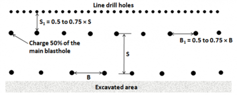
The technique of line drilling is among the earliest controlled blasting method utilized in mining operations where rock mass is of homogeneous nature [13]. The purpose of line drilling is to create a plane of weakness by drilling closely spaced, small diameter holes along the perimeter of the rock mass which needs to be blasted (Figure 1). The diameter of line drill holes is usually kept within 75 mm and spacing is maintained approximately 2 to 4 times the diameter of the hole. The depth of the line drill holes should not be more than be more 12 m since the deviation in longer holes may produce adverse results. The line drill holes are not charged as the shock energy from the main blast result in inter-blast hole splitting within the individual holes drilled in a line. Further, this method is applied in very sensitive areas where even the light explosive associated with other controlled blasting technique may cause damage beyond excavation line. Apart from that, it has been observed that Line drilling system with closed spacing can arrest the ground vibration to be propagated beyond the excavation limit to a great extent. Because of these advantages, this technique is widely used for construction excavations such as foundation excavation for high rise buildings etc. The high drilling cost and poor blast hole alignment are some of the major disadvantage of this technique.
Figure 1. Line drilling design
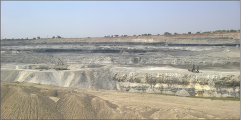
The Ground vibration due to blasting of Dragline bench is reduced by controlled blasting technique of line drilling at Jayant Project. The line drilling is done in high wall of blast patch. Apart from arresting seismic waves the line drilling technique provides smooth high wall for workings in dragline cut and also provides safety against rocks falling from high wall. In the present study, the holes of line drill were kept at a distance of 4 m from the last row of dragline blast holes with spacing of 3 to 4 m. The diameter of holes was kept to 270 mm and hole depth were maintained within the range of 20 m to 27 m. Two rows of line drills were experimented at the benches where soft to medium sandstone were present and it was found that the results were reassuring the stability of high wall. Few of the line drill faces are presented in Figure 2.
Figure 2. Blasting face with line drilled blastholes at Jayant opencast project
The Jayant project of Northern Coalfields Limited is located in the Singrauli Coalfields of Singrauli district, Madhya Pradesh between latitudes 24°6'45"to 24°11'15" and longitudes 82°36'40" to 82°41'15". The overall geomorphology of the project site mainly comprised of elevated plateau like feature having elevation ranging from 300 m to 500 m above the M.S.L. The lithological associations of the region are mainly belonging to Lower Gondwana Formation. The area comprised of five major coal seams, i.e. Kota, Turra ‘A’, Turra, purewa Bottom and Purewa Top (Figure 3). Kota and Turra 'A'. The seam thickness of Turra varies from 13 to 19m. The thickness of Purewa bottom and Purewa Top varies from 9 to 12m and 5 to 9m respectively. There are number of dirt bands in Turra Seam, some of which are more than 1m in thickness. The strike of the coal seam is from east to west and the dip varies from 10 to 4 degree in northern direction. All the five major coal seams are comprised of coals having varying grades viz. the Turra seam has C and D grade, Purewa Bottom seam has D, E grade, Purewa Top seam has E and F grade of coal. The overview of the Jayant Opencast Project is shown in Figure 4.
Figure 3. Overall view of the different coal deposition and overburden at Jayant Opencast Project
Figure 4. The overview of the Jayant opencast Project, NCL, Singrauli, India
Fifty-six blasts were conducted at dragline benches of East and West sections of Jayant project, out of which electronic delay detonators were used in 26 blasts, detonating cord were used in 21 blasts and rest 9 blasts were detonated using pyrotechnic detonation system (NONEL). The number of holes detonated in a blast round was varied from 16 to 70 blastholes. The depth of holes varied from 27 m to 38 m. The diameter of blast holes was approximately 269 and 311 mm for dragline benches. The explosives loaded in a hole varied from 1,150 to 2,300 kg for dragline blast. Total explosive weight detonated in a blast round varied between 1279 to 84,000 kg. The vibration measuring distances ranged from 200 to 5,480 m. Summary of blasts experimented during the study are given in Table 1.
Table 1. Summarized blast details of experimental site
|
Blasting details |
Details of data |
||
|
Electronic |
NONEL |
D-Cord |
|
|
No. of blasts |
26 |
9 |
21 |
|
No. of PPV data recorded |
47 |
27 |
22 |
|
Range of total explosive weight detonated (kg) |
1600-525203 |
678-83731 |
32245-113837 |
|
Range of explosive weight per delay detonated (kg) |
950-2000 |
1061-2300 |
1356-2391 |
|
Range of distance (m) |
860-4890 |
1350-5480 |
1920-4557 |
|
Range of recorded PPV (mm/s) |
0.596-9.3 |
1.33-8.24 |
0.397-8.75 |
|
Range of dominant peak frequency (Hz) |
2.0-21.0 |
2.0-20.5 |
4.44-30 |
Ground vibrations data recorded were grouped together for statistical analysis. An empirical relationship has been established correlating the maximum explosive weight per delay (Qmax in kg), distance of vibration measuring transducers from the blasting face (R in m) and recorded peak particle velocity (v in mm/s). The established site specific equation for the mine is:
$V=182.34\left(\frac{R}{Q_{\max }}\right)^{-1.066}$ (1)
Correlation co-efficient = 76 %
Coefficient of determination = 0.5904
where,
v=Peak particle velocity (mm/s)
R=Distance between vibration monitoring point and blasting face (m)
Qmax=Maximum explosive weight per delay (kg)
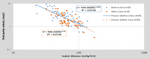
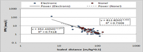
The regression plots of vibration data recorded at their respective scaled distances is presented in Figure 5. Ground vibration data recorded without line drilling and with line drilling were also compared to assess the variation in ground vibration data and the impact of line drilling was recognized (Figure 6). Ground vibration data recorded from pyrotechnic initiation system (Nonel) and electronic initiation system were also compared to see the variation and/or impact of initiation system on ground vibration (Figure 7).
Figure 5. Regression plot of recorded PPV at their respective scaled distances
Figure 6. Comparative plot of vibration data recorded with and without line drilling
Figure 7. Comparative regression plot of recorded PPV at their respective scaled distances for Nonel and electronic delay initiation system
Peak particle velocity (PPV) has been globally used in practice for assessment of blast-induced damage to structures. Different countries adopt different standards depending on their type of industrial/residential buildings. In India, presently DGMS technical circular 7 of 1997 is considered as vibration standard for the safety of surface structures in mining areas. The DGMS standard is given in Table 2.
Table 2. DGMS technical circular 7 of 1997 concerning to blast vibration standard, PPV in mm/s
|
Type of structure |
Dominant excitation frequency, Hz |
||
|
|
<8 Hz |
8-25 Hz |
>25 Hz |
|
|||
|
1. Domestic houses/structures (Kuchcha, brick & cement) |
5 |
10 |
15 |
|
2. Industrial buildings |
10 |
20 |
25 |
|
3. Objects of historical importance and sensitive structures |
2 |
5 |
10 |
|
(B) Buildings belonging to owner with limited span of life |
|||
|
1. Domestic houses/structures |
10 |
15 |
25 |
|
2. Industrial buildings |
15 |
25 |
50 |
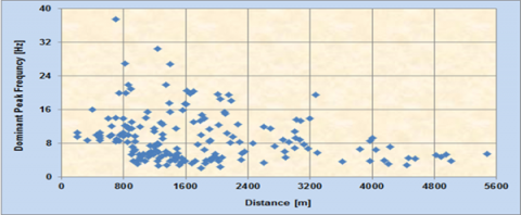
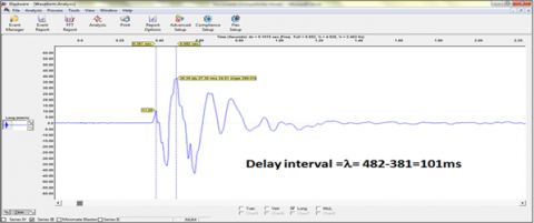
The dominant frequencies of ground vibrations data recorded were in the range of 2.13 to 37.5 Hz. The plot of recorded dominant frequencies at various locations is given in Figure 8. The blast wave signature recorded from the blast conducted at East Section dragline bench near at 2180 m distance is shown in Figure 9 which indicates the low amplitude vibration with persistence up to 4.5 seconds. The Fast Fourier Transform (FFT) analyses of frequencies of vibration signature shown in Figure 9 were depicted in Figure 10.
Figure 8. Plot of dominant frequencies of blast waves recorded at various locations in the periphery of the Jayant project
Figure 9. Blast wave signature recorded at 2000 m from the blast conducted at dragline bench West section of Jayant Opencast Mine
Figure 10. FFT analyses of frequencies of vibration signature recorded at 2000 m as presented in Figure 4
6.1 Blast delay optimisation with the help of signature blast
The optimum blasts have the following objectives:
- Adequate rock fragmentation, swelling and displacement
- Control over the fly rocks and over breaks
- Minimum level of vibration and air blasts
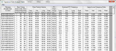
The delay timing between the holes in a row and between rows plays fundamental role in fulfilment of these objectives. To address this issue a blast hole was drilled at Dragline bench of East Section and was loaded with 1600 kg of explosives and was fired instantaneously without in-hole delay. The blast wave signatures were recorded at 200m and 400m. The attenuation characteristics of blast were documented. The typical time history of blast wave signature recorded at 200 m from the blast hole is presented in Figure 11. The frequency spectra of the signature blast were analysed. Linear superposition of the waves was done to simulate the waveform characteristics for multi-hole blasting. The analyses revealed that very short delay times between the holes and very long delay intervals between the rows should be avoided. The analyses further concluded that the mean time needed to start the movement of rock face is 7.22- 9.3 ms/m of effective burden. The delay interval between the successive rows should be 11.2 to 18.4 ms/m of effective burden. The blast designs were optimised considering the output of linear superimposition techniques. The suggested delay interval between the holes was of 17 ms. The signature hole analysis in table is presented as Figure 12. The blast conducted with optimised blast designs resulted into excellent fragmentation with no back break.
Figure 11. Time history of the signature blast in Longitunal direction
Figure 12. Signature blasthole analysis result
7.1 Monitoring of velocity of detonation (VOD) of explosives
The performance of explosives depends upon a number of parameters and VOD is one of the important parameters. The detonation pressure associated with the reaction zone of a detonating explosive is directly proportional to the square of its VOD. It is measured in the C-J plane, behind the detonation front, during propagation through the explosive column. The detonation pressure (Pd) can be estimated by the following formula.
$P_{d}=\frac{1}{2} \rho_{e}(V O D)^{2} 10^{-6}$ (2)
where,
Pd= Detonation pressure (MPa)
re= Density of explosive (kg/m3)
VOD = Velocity of detonation (m/s)
Figure 13. The recorded in-the-hole VOD of SME Explosives recorded at dragline bench of East Section, Jayant Project
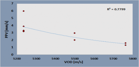
Uniform in-the-hole VOD of explosive is essentially required throughout the blast holes in order to produce sufficient detonation pressure to the blast hole walls. Booster is provided in the explosive column at bottom to sustain and maintain the VOD for the uniform breakage of rock. The recorded in-the-hole VOD was in the range of 5234.6 m/s to 5762.2 m/s. One of the trace of VOD is presented in Figure 13. Nine PPV observations were recorded at 1000 m distance with three varying VODs to evaluate the impact on ground vibration. The general observation indicates that higher VOD generates lesser ground vibrations although total charge and maximum explosive weight per delay have a significant influence.
7.2 Quality tests of blasting accessories
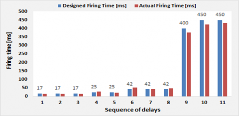
The qualities of Nonel initiation system were tested with the help of Blaster Ranger II, High Speed Colour Video camera (at 500 fps). Tests were performed for the surface delays of 17, 25, 42 & down the hole delays of 400 ms and 450 ms. Both positive and negative scattering were observed. The maximum scattering of 23.8 % was recorded in trunk line delay of 42 ms. The influence of scattering on blast performance is obvious and needs further investigation to mark the extent of its impact.
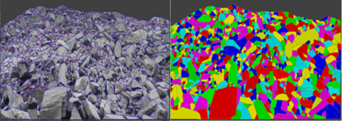
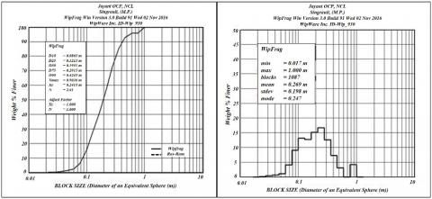
The fragmentation analyses were carried out for blasts conducted at dragline benches of East and West sections. The output of the analyses is in the form of number of exposed fragmented blocks, maximum, minimum and mean size of the fragmented blocks, sieve analysis as per the requirement i.e. at different percentile size viz. D10, D25, D50, D75& D90. (Percentile sizes: for example D10 is the ten-percentile, the value for which 10 % by weight of the sample is finer and 90 % coarser). In terms of sieving, D10 is the size of sieve opening through which 10 % by weight of the sample would pass.
The fragmentation resulted due to one of the blast conducted at dragline bench is presented in Figure 14. The process involved in analyses of fragmentation is shown in Figures 15 and 16. The blasted block size distribution of East Dragline bench and West Dragline bench of Jayant project (m) is given in Table 3.
Figure 14. Over view of fragmentation resulted due to blasting at Dragline bench of East section of Jayant Opencast Project
Figure 15. Netting and contouring of fragmented material shown in Photograph 4
Figure 16. Histogram and cumulative size curve generated after rock fragmentation analysis
Table 3. Blasted block size distribution of East Dragline bench and West Dragline bench of Jayant Opencast project
|
S. No. |
Blast Bench Name |
D10 |
D25 |
D50 |
D75 |
D90 |
Xmax |
Xc |
n |
|
1. |
DL Bench East Section |
0.08 |
0.12 |
0.19 |
0.29 |
0.42 |
0.30 |
0.24 |
2.01 |
|
2. |
DL Bench East Section |
0.07 |
0.10 |
0.15 |
0.23 |
0.60 |
0.23 |
0.19 |
2.04 |
|
3. |
DL Bench West Section |
0.09 |
0.12 |
0.18 |
0.29 |
0.53 |
0.28 |
0.22 |
2.05 |
|
4. |
DL Bench West Section |
0.13 |
0.20 |
0.37 |
0.57 |
0.87 |
0.61 |
0.48 |
1.91 |
The analyses of blast induced ground vibration data clearly indicates that there is a remarkable decrease in ground vibration level due to line hole drilling (Figure 7). It was further found that in case of electronic delay detonators less ground vibrations were recorded in comparison to pyrotechnic delay detonators.
The maximum vibration recorded in terms of peak particle velocity (PPV) was 42.1 mm/s at 330 m on the ground surface behind the blasting face. The associated dominant peak frequency was 8.7 Hz. This magnitude of vibration was due to detonation of 27850 kg of explosives loaded in 13 holes in two rows and fired with maximum charge weight per delay of 1050 kg. The PPV recorded at 1010 m from the same blast was 3.48 mm/s with dominant peak frequency of 4.63 Hz. It indicates that attenuation of vibration is very fast.
The FFT analyses of vibration data revealed that the concentration of vibration energy up to a distance of 800 m was more than 8 Hz and overall it varied between 2.13 - 37.5 Hz. Thus, the safe level of vibration has been taken as 10 mm/s for the safety of houses/structures in close proximity of the Jayant project i.e. up to 800 m from the blasting face and for beyond 800 m it should be 5 mm/s as per DGMS standard.
Simulation of waveform characteristics were done by Linear superposition of the waves. The analyses result revealed that very short delay times between the holes and very long delay intervals between the rows should be avoided. It was further determined that the mean time needed to start the movement of rock face is 7.22- 9.3 ms/m of effective burden. The delay interval between the successive rows should be 11.2 to 18.4 ms/m of effective burden. The blast designs were optimised considering the output of linear superimposition techniques. The suggested delay interval between the holes was of 17 ms.
Quality test of explosives reveal that the recorded in-the-hole VOD was in the range of 5234.6 m/s to 5762.2 m/s i.e. found to be provide sufficient detonation pressure for fragmentation of rockmass. It was observed that with increasing VOD the PPV reduces exponentially (Figure 17).
Rock fragmentation analyses were carried out for Dragline bench blasts of East and West Sections. The analyses indicated that trial blasts resulted with very good fragmentation. The mean sizes of boulders were in the range of 0.269 m to 0.490 m and maximum sizes of boulders were in the range of 1.00 to 1.29 m. There was very little back-break in few blasts. The blast designs were optimised and were experimented which resulted into excellent blast results.
Figure 17. Plot of peak particle velocity (PPV) with respect to velocity of detonation (VOD) at a distance of 1000 m
Figure 18. Comparative plot of scattering in pyrotechnic delay detonators
Line drilling controlled blasting technique was successfully being implemented at Jayant Opencast mine. The holes of line drill kept at a distance of 4 m from the last row of dragline blast holes with spacing of 3 m gave best results. The outcomes of line drilling were observed well in reduction of ground vibration as well as forming the safe and stable high wall. Apart from line drilling it was further found that electronic delay detonators were more effective in reduction of blast vibration. The attenuation characteristics of blast vibrations indicates fast attenuation with increasing distance.
On the basis of FFT analyses of vibration data it was observed that the concentration of vibration energy up to a distance of 800 m was more than 8 Hz and overall it varied between 2.13 - 37.5 Hz. Therefore, the safe level of vibration in close proximity of the Jayant project i.e. up to 800 m has been taken as 10 mm/s from the blasting face and for beyond 800 m it should be 5 mm/s as per DGMS standard.
Linear superposition was used to simulate the waveform characteristics. It was concluded that the mean time needed to start the movement of face is 7.22 – 9.3 ms/m of effective burden. It was further concluded that the delay interval between the successive rows should be 11.2 to 18.4 ms/m of effective burden and the delay interval between the holes was of 17 ms.
To check the quality of explosives in-the-hole VOD was recorded that comes in the range of 5234.6 m/s to 5762.2 m/s and found suitable for the breakage of the rock mass. The scattering test results of TLDs and DTHs reveal that both negative and positive scattering were present in the pyrotechnic delays.
The authors express their gratitude to the officials of Jayant opencast mine for providing necessary facilities during the course of this study. The authors are also thankful to Director, CSIR-Central Institute of Mining and Fuel Research, Dhanbad, India for his encouragement and support during the field study. The opinions are those of the authors and not necessarily the organizations to whom they belong.
[1] Paswan, R.K., Mohammad, S., Singh, P.K., Khare, H.S., Singh, B.K., Singh, R.J. (2014). Controlled blasting at Parsa East & Kanta Basan opencast mines for safe and efficient mining operations. The Indian Mining & Engineering Journal, 53(4): 7-17.
[2] Siskind, D.E., Stagg, M.S., Kopp, J.W., Dowding, C.H. (1980). Structure response and damage produced by airblast from surface mine blasting. U.S. Bureau of Mines, RI 8485, 111.
[3] Singh, P.K., Vogt, W., Singh, R.B., Singh, D.P. (1996). Blasting side effects—investigations in an opencast coal mine in India. Int. J. of Surface Mining Reclamation and Environment, the Netherlands, 10(4): 155-159. http://dx.doi.org/10.1080/09208119608964824
[4] Rogers, W.D., Kanchibotla, S.S. (2012). Application of stochastic approach to predict blast movement. International Symposium on Rock Fragmentation by Blasting, FRAGBLAST, 10: 257-265. https://doi.org/10.1201/b13759-34
[5] Garai, D., Mishra, A.K., Kumar, S., Agrawal, H. (2018). Development of an iniversal blast-induced ground vibration prediction model for Jharia Coalfields. Modelling, Measurment and Control C, 79(2): 46-55. https://doi.org/10.18280/mmc_c.790205
[6] ISEE Blasters’ Handbook. 18th Edition. Chapter 13–Initiation Systems. 268.
[7] Jimeno, C.L., Jimeno, E.L., Carcedo, F.J.A. (1995). Drilling and blasting of rocks. A. A. Balkema, Rotterdam, the Netherlands, 391.
[8] Singh, P.K, Roy, M.P., Paswan, R.K., Dubey, R.K., Drebenstedt, C. (2015). Blast vibration effects in an underground mine caused by open-pit mining. International Journal of Rock Mechanics and Mining Sciences, 80: 79-88. https://doi.org/10.1016/j.ijrmms.2015.09.009
[9] Paswan, R.K., Roy, M.P., Md. Sarim., Kumar, S. (2017). Blast induced damage and role of discontinuities on pre-split blasting at Rampura-Agucha Pb-Zn Open pit mine. International Conference on NexGen Technologies for Mining & Fuel Industries (NxGnMiFu-2017). February 15-17, 2017, Vigyan Bhawan, New Delhi, India, pp. 281-290.
[10] Worsey, P.N., Farmer, I.W., Matheson, G.D. (1981). The mechanics of pre-splitting in discontinuous rock. Proceedings, 22nd U.S. Rock Mechanics Symposium, pp. 205-210.
[11] Worsey, P.N., Qu, S. (1987). Effect of joint separation and filling on pre-splitting blasting. Proceedings of the 3rd Symposium on Explosives and Blasting Research, ISEE, Miami, Florida, U.S.A., pp. 26-40.
[12] Singh, S.P. (2005). Blast damage control in jointed rock mass. Fragblast, 9(3): 175-187. https://doi.org/10.1080/13855140500293280
[13] Rustan, A. (1998). Rock blasting terms and symbols – A dictionary of symbols and terminology in rock blasting and related areas like drilling, mining and rock mechanics. A. A. Balkema/Rotterdam/Brookfield., 39.