S. V. Sathvika | Muthuram N.* | Brajesh Kumar Kanchan
© 2024 The authors. This article is published by IIETA and is licensed under the CC BY 4.0 license (http://creativecommons.org/licenses/by/4.0/).
OPEN ACCESS
Heat exchangers enable processing plants to maintain maximum performance over time when handling variable process conditions. The most frequent heat exchanger issues, however, can occasionally be far more challenging to fix, resulting in high capital expenses and rising running costs. Consequently, there is a crucial need to redesign the current heat exchanger for improved performance. In this work, a shell and tube-type heat exchanger is designed with the help of CREO 8.0 parametric software. Transient thermal analysis is done to the designed model using ANSYS 2022 R2 software to investigate different shell and tube heat exchanger materials and assess the heat exchanger for its efficiency and temperature gradient. These results can be used to design appropriate heat exchangers in stationary energy systems, including power plants and fuel cell systems.
heat exchanger, energy efficiency, shell and tube heat exchanger, heat transfer, transient thermal analysis, temperature gradient
A variety of industries, including power generation, oil and gas refineries, industry, ships, and on-road and off-road machinery, energy systems use hell and Tube heat exchangers because they are strong, dependable, and available in a range of sizes, from large custom-built units like feedwater heaters to small off-the-shelf hydraulic oil coolers [1]. Heat exchangers made of shell and tube have a long lifespan, no moving parts, and minimum maintenance needs. Nevertheless, it is imperative to treat them with care, as these vital machines are exposed to various risks that could affect their ongoing optimal performance. A heat exchanger malfunction or failure could frequently result in a total shutdown of operations [2]. One can choose from various heat exchanger designs, such as tubular, double-pipe, flat plate, spiral, and coil designs. Numerous factors influence the choice of a heat exchanger design [3, 4]. The majority of heat exchangers are categorized based on the way they are made, how they transmit heat, and how compact their surfaces are [5]. About the physical size, that is the amount of surface area where the heat can escape or be transferred [6]. Heat exchangers are designed explicitly for improved performance and minimized thermal fatigue during the operation.
Various research articles were studied from the literature to redesign the existing shell and tube heat exchangers. Baydaa et al. [7] presented a design for an oil cooler with a baffle for induced turbulence and higher heat transfer coefficient. The heat transfer rate is high with less stress for brass material with baffle, and the drop in pressure on shell and tube side and heat transfer coefficients were observed with a variation of 4.4%, 6.3% and 2.7% and match with HTRI software. Rajkamal et al. [8] presented the thermal analysis of the replaceability of copper with POCO HTC graphite and ASTM SA 179 carbon steel for the inner tubes of a helical coil heat exchanger modeled with a helix angle of 30°. It is inferred from ANSYS CFX that POCO HTC graphite conducts heat better and has high corrosion resistance. Moreover, it was found that for constant temperature with varied increasing mass flow rates, the heat transfer characteristics also increase. Andrea et al. [9] conducted a preliminary quantitative analysis of intermediate- size heat exchangers using reference design data from the SAMOFAR H2020-Euratom project. Hypotheses were developed on intermediate loop temperatures, and a safety margin was identified to avoid the solidification of the fuel salt. Surender Kumar [10] has carried out a design model of a counterflow shell and tube-type heat exchanger where water acts as the working fluid and is done by Kern's method and the regulations of the tubular exchanger manufacturer's association. It was found that the results of the analysis and experiment were within the same range, and the effectiveness value was 0.333(copper material). Jakka et al. [11] have presented entropy reduction with constrained thermodynamic optimization in a parallel flow heat exchanger for materials like mild steel, stainless steel and nickel. It is concluded that the design parameters were verified as the entropy minimization was done successfully. Sousa et al. [12] have exhibited the capability of integrated bypass-flow surface heat exchangers to withstand innovative engine architecture's high cooling demands. The bypass section of a turbo-fan engine resulted in 76% of the current aero-engine cooling demand at plane take-off conditions, and cooling fluctuations were below 10% during the full flight range. Dhavamani et al. [13] fabricated by casting the shell and tube type heat exchanger with the helical angle of 30˚ and calculated the effectiveness of heat transfer. The components were designed using the Kerns method to reduce water temperature from 85℃ to 55℃. The effectiveness was increased by 10% when they used the spiral tube compared to the parallel flow heat exchanger, and the heat transfer rate increased. Jamshak et al. [14] have redesigned the conventional heat exchanger to a plate-type heat exchanger to improve performance and reduction of cost. The new design occupies less space than the regular heat exchanger. By increasing the number of plates, the performance has also been increased, and the reduced cost is about Rs 3,60,000/, which was found to be a safe and secure implementation method. Ashish et al. [15] investigated refinery processes happening in a double-pipe heat exchanger using CFD analysis in ANSYS. The fins of the heat exchanger were organized in a way that works as a baffle plate, in turn, guides the fluid inside the shell of the heat exchanger. It is reported that as the fin thickness increases, cold fluid temperature increases, and there is little change in the pressure and velocity. Santhisree et al. [16] have presented the study of thermal analysis of shell and tube-type heat exchangers in ANSYS fluent 15.0. Kerns method was adopted to do the preliminary design of the component. The model predicts the heat transfer and pressure drop with an error of 25%, which has scope for improvement. Gupta et al. [17] presented the utilization of shell and tube heat exchangers with three materials: aluminium, steel and copper. It is reported that copper gave the best result compared to aluminium and steel based on temperature and effectiveness. Saydam et al. [18] have modeled, fabricated and analyzed experimentally for thermal storage performance under various working conditions for a miniature PCM helical coil heat exchanger. Inlet temperature increased from 70℃ to 75℃, reducing the charging time by 21% and increasing the flow rate from 0.5 to 4 L/min. Sharma et al. [19] studied the thermal analysis of water and oil-type shell and tube heat exchangers. They proposed theoretical formulas for a real-life problem of counter flow shell and tube type heat exchanger, using the calculation. The thermal analysis results for copper and stainless steel have an error difference of 0.023 in effectiveness. Patel et al. [20] have carried out the thermal analysis of tube-type heat exchanger with Ansys (CFD analysis) for two materials - copper and aluminium - the effect of the materials has been examined. The analysis used hot and cold water with 90°C and 27℃ temperatures and 2 Kg/sec and 40 Kg/Sec mass flow rates. It was reported that aluminium provides higher heat transfer rates. Several other research highlight the various possibilities of heat transfer [21, 22].
From the literature, it was understood that a comparison study of analysis between various heat exchangers was not done[23, 24]. In the present study, modeling of the heat exchanger was done. Thermal analysis is then performed on the heat exchanger for various materials using ANSYS 2022 R2 software. The alignment of the tubes is also changed and analyzed.
The present study involves designing and analyzing shell and tube-type heat exchangers for improved effectiveness. There are 58 unique components in the shell and tube-type heat exchanger selected for design and analysis. The existing design was studied, and each component was designed and assembled using CREO Parametric 8.0 software. The assembled component was imported in ANSYS 2022 R2 workbench software to conduct a Transient thermal analysis of the heat exchanger with necessary boundary conditions, appropriate working fluid and material selections. The thermal design parameters like flow rate, inlet temperature, outlet temperature, heat flux, temperature distribution, heat transfer coefficient of the materials, heat recovery efficiency, and pressure drop and the mechanical design parameters like wall thickness of the shell, U-tube, channels were taken into considerations for the analysis. In a heat exchanger, the energy flows from the hot fluid through the barrier and into the cold fluid. To account for this, the total thermal resistance (K/W) is given by Eq. (1) [19],
$\begin{gathered}R=R i+R w a l l+R o \\ R=(1 / h i A i)+\ln (D o / D i) / 2 \Pi k l+(1 / h o A o)\end{gathered}$ (1)
$\mathrm{R}_{\mathrm{wall}}=$ Thermal resistance of wall $(\mathrm{K} / \mathrm{W})$
$\mathrm{R}_{\mathrm{i}}=$ Thermal resistance inside the wall $(\mathrm{K} / \mathrm{W})$
$\mathrm{R}_{\mathrm{o}}=$ Thermal resistance outside the wall $(\mathrm{K} / \mathrm{W})$
$\mathrm{k}=$ Thermal conductivity $\left(\mathrm{Wm}^{-1} \mathrm{~K}^{-1}\right)$
$\mathrm{L}=$ Length of the tube $(\mathrm{m})$
$A_0=$ Area of the outer surface of the wall $\left(\mathrm{m}^2\right)$
$A_i=$ Area of the inner surface of the wall $\left(\mathrm{m}^2\right)$
$\mathrm{h}=$ Heat transfer coefficient $\left(\mathrm{W} / \mathrm{m}^2 / \mathrm{K}\right)$
The proportionality constant is the material's thermal conductivity [19].
$Q=-k A$ (2)
In Eq. (2), Q is the rate of heat transfer $(\mathrm{J} / \mathrm{s}), \mathrm{k}$ is the material's thermal conductivity $\left(\mathrm{Wm}^{-1} \mathrm{~K}^{-1}\right), \mathrm{A}$ is the area normal to the direction of the flow of heat $\left(\mathrm{m}^2\right)$, and $\mathrm{dT} / \mathrm{dx}$ is the temperature gradient. Convection is the fluid's bulk motion against the wall's surface, thus transferring thermal energy. This phenomenon is represented by Newton's Law of Cooling, which states that the rate of heat loss is proportional of a body to the difference in the temperature of the body and its surroundings [19].
$Q=h A \Delta T$ (3)
In Eq. (3), ' $Q$ ' is the rate of heat transfer $(\mathrm{J} / \mathrm{s})$, ' $A$ ' is the area normal to the direction of the flow of heat $\left(\mathrm{m}^2\right)$, and ' $\Delta T$ ' is the temperature difference between the wall and bulk fluid. The convective heat transfer coefficient is denoted by ' $h$ '.
2.1 Preliminary Modeling
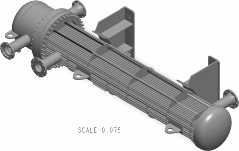
A 636 mm flange and cylinder tube body of the heat exchanger are attached. Two lifting lug plates are attached to the body of the model. The identification plate is also fixed on the body of the heat exchanger. A shell cover is fixed to the other side of the cylindrical tube. A support saddle and a mobile support saddle are fixed to the model for standing support. The shell sub-assembly and tube subassembly was done by bending the tube sheet, and thirty spacer tubes of various diameter were attached with baffle plates in between. Sixty-eight tubes are attached to the tube sheets. The tube sub- assembly and the shell sub-assembly are assembled in the software CREO Parametric 8.0.8.0 assembly environment. The assembly of the preliminary model is shown in Figure 1.
Figure 1. Isometric view of heat exchanger modeled on CREO parametric
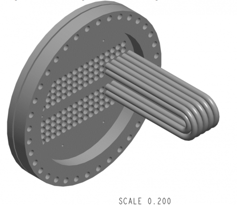
Since the volume of components is vast, a quarter model consisting of 10 clusters of tubes is chosen to perform the transient thermal analysis in ANSYS workbench software. CREO 8.0.8.0 parametric software was used to model the redesigned heat exchanger, as shown in Figure 2.
Figure 2. Isometric views of parts of the redesigned heat exchanger model
2.2 Transient thermal analysis
Transient thermal analysis was performed on the heat exchanger shown in Figure 2 and studied the temperature gradient acting on it using ANSYS 2022 R2 – workbench software. In the ANSYS 2022 R2 workbench software, transient thermal analysis option, engineering data source, material, and aluminium were selected. The already modeled file of the quarter model was uploaded in geometry, and aluminium material was assigned to all the U-tubes. To build a numerical model, the mesh was generated, and in the sizing option, the fine mesh was selected based on the mesh independence study. The transient thermal option was selected, and the boundary condition temperature was inserted. Boundary conditions:
Condition 1: (hot water passing through the tube)
The temperature of hot water inside the tube $\left(\mathrm{t}_{\mathrm{hi}}\right)=90^{\circ} \mathrm{C}$
The temperature of cold water in the shell $\left(\mathrm{T}_{\mathrm{ci}}\right)=27^{\circ} \mathrm{C}$
Condition 2: (cold water passing through the tube)
The temperature of cold water inside the tube $\left(\mathrm{T}_{\mathrm{ci}}\right)=27^{\circ} \mathrm{C}$
The temperature of hot water in the shell $\left(t_{\text {hi }}\right)=90^{\circ} \mathrm{C}$
Meshing details:
Number of nodes =78043
Elements =31343
2.3 Redesigning of the heat exchanger
All the primary dimensions are designed for the following requirements of the heat exchanger.
The temperature of hot water inside the tube, $\mathrm{T}_{\mathrm{hi}}=90^{\circ} \mathrm{C}$
The mass flow rate of hot water, $\mathrm{M}_{\mathrm{h}}=2 \mathrm{~kg} / \mathrm{s}$
The mass flow rate of coolant, $\mathrm{M}_{\mathrm{c}}=40 \mathrm{Kg} / \mathrm{s}$
Specific heat of water, $\mathrm{C}_{\mathrm{h}}=4180 \mathrm{~J} / \mathrm{KgK}$
The temperature of hot water after cooling the tube, $\mathrm{T}_{\mathrm{ho}}=70^{\circ} \mathrm{C}$
The temperature of coolant inside the shell, $\mathrm{T}_{\mathrm{Ci}}=27^{\circ} \mathrm{C}$
The inner diameter of the tube, $\mathrm{D}_{\mathrm{i}}=41.89 \mathrm{~mm}$
Specific heat of coolant, $\mathrm{C}_{\mathrm{c}}=2500 \mathrm{~J} / \mathrm{KgK}$
Heat transfer rate, $Q=M \quad{ }_h C \quad{ }_h \Delta T \quad{ }_h=3344 \mathrm{~kW}$
To find the temperature of coolant after cooling using Eq. (4), $\mathrm{T}_{\mathrm{co}}[19]$
$Q=\operatorname{McCc} \Delta T c===\Rightarrow \mathrm{T}_{\mathrm{co}}=\quad \mathrm{T}_{\mathrm{Ci}^2}+\quad \mathrm{Q} / \mathrm{M}_{\mathrm{c}} \mathrm{C}_{\mathrm{c}}=60.44^{\circ} \mathrm{C}$ (4)
Log mean temperature difference [19],
$\Delta T_{\mathrm{lm}}=\left(\mathrm{T}_{\mathrm{ho}}-\mathrm{T}_{\mathrm{co}}\right)-\left(\mathrm{T}_{\mathrm{hi}}-\mathrm{T}_{\mathrm{Ci}}\right) / \ln \left(\left(\mathrm{T}_{\mathrm{ho}}-\mathrm{T}_{\mathrm{co}}\right) /\left(\mathrm{T}_{\mathrm{hi}}-\mathrm{T}_{\mathrm{Ci}}\right)\right)$ (5)
$\begin{aligned} & \Delta T_{\operatorname{lm}}=-53.44 /-1.885=28.3419 \mathrm{~K} \\ & \text { Overall heat transfer, } \mathrm{Q}=\mathrm{UA} \Delta T_{\operatorname{lm}}=\Delta T_{\operatorname{lm}} / \mathrm{R}_{\text {tot }} \\ & \mathrm{R}_{\text {tot }}=\Delta T_{\operatorname{lm}} / \mathrm{Q}====>28.3419 \mathrm{~K} / 3344 \mathrm{KW} \\ & =0.008475 \mathrm{~K} / \mathrm{W}\end{aligned}$ (6)
Another way to find total thermal resistance $R_{\text {tot }}$, is with a pipe wall, which is in contact with both hot and cold liquid. Since it's a thin-walled pipe, it is assumed that no conduction is carried out.
Convection heat transfer from the hot side $=\mathrm{h}_{\mathrm{i}}=700 \mathrm{~W} / \mathrm{m}^2 \mathrm{~K}$
Heat transfer from the cold side is $h_0=1300 \mathrm{~W} / \mathrm{m}^2 \mathrm{~K}$
Fouling factors due to buildup formed on the tube of the heat exchanger is $=0.0002 \mathrm{~m}^2 \mathrm{~K} / \mathrm{W}$
$\begin{aligned}& \mathrm{R}_{\text {tot }}=\left(1 / \mathrm{h}_{\mathrm{i}} \mathrm{A}\right)+\left(\mathrm{R}_{\mathrm{fi}} / \mathrm{A}\right)+\left(\mathrm{R}_{\mathrm{fo}} / \mathrm{A}\right)+\left(1 / \mathrm{h}_{\mathrm{o}} \mathrm{A}\right)=0.0026 / \mathrm{A}\left(\mathrm{m}^2 \mathrm{~K} / \mathrm{W}\right) \\& 0.008475 \mathrm{~K} / \mathrm{W}=0.0026 / \mathrm{A} \\& \mathrm{A}=0.0026 / 0.008475=0.306 \mathrm{~m}^2 \\& \Pi \mathrm{D}_{\mathrm{i}} \mathrm{L}=0.306 \mathrm{~m}^2 \\& \mathrm{~L}=2.325 \mathrm{~m}\end{aligned}$
The length of the internal tube is $2325 \mathrm{~mm}$
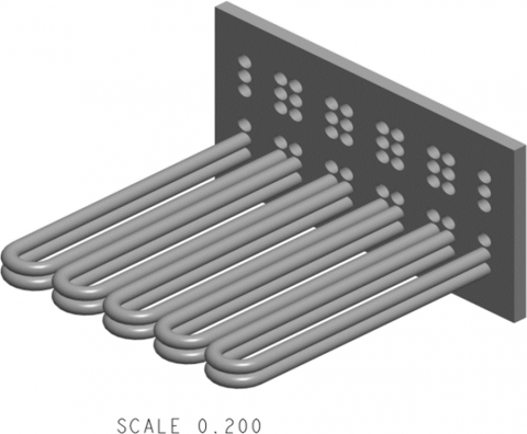
Figure 3. Isometric view of the heat exchanger, tubes arranged in a linear fashion
In the redesigned heat exchanger, the arrangement of the U- tube is made linear instead of circular pattern, as shown in Figure 3.
Also, the optimized design of the redesigned heat exchanger assembly was changed to copper material, and the characteristics of the newly designed model were compared with those of the existing model.
Transient thermal analysis was performed on the copper heat exchanger and the temperature gradient acting on it using ANSYS 2022 R2 – workbench software. The analysis was performed, with the same boundary conditions provided for the existing model, for the quarter model geometry of 10 clusters of tubes, and the results were extrapolated for the entire heat exchanger.
Boundary conditions:
Condition 1: (hot water passing through the tube)
The temperature of hot water inside the tube = 90℃
The temperature of cold water in the shell = 27℃
Condition 2: (cold water passing through the tube)
The temperature of cold water inside the tube = 27℃
The temperature of hot water in the shell = 90℃
The mass flow rate of the hot water = 2Kg/s in each tube
The mass flow rate of the cold water = 40Kg/s in the shell
Meshing details:
Number of node = 78043
Elements = 31343
3. Mesh independence study
It is observed that the results have stopped changing from mesh element size 0.1 mm, as shown in Table 1 and Figure 4. Hence, the 0.1 mm element size was the optimum element size. Refining the element size will not affect the results produced.
Table 1. Results obtained from thermal analysis of the heat exchanger designed for hot water conditions and mesh data
|
ELEMENTS SIZE |
MAX TEMP |
MIN TEMP |
|
0.05 mm |
368.33K |
329.56K |
|
0.075 mm |
368.433K |
329.556K |
|
0.1 mm |
368.413K |
329.416K |
|
0.125 mm |
368.413K |
329.416K |
|
0.15 mm |
368.413K |
329.416K |
Figure 4. Mesh convergence
3.2 Model validation
Transient thermal analysis was performed on the heat exchanger. The heat exchanger design is validated by comparing the results obtained from the thermal analysis done by Paresh et al. [16] thermal Analysis of Tubular Heat exchangers using ANSYS. Since the results obtained from the numerical analysis agree with the experimental data reported in the literature, the presented numerical model is sufficient to accurately investigate the performance of the redesigned heat exchanger model shown in Table 2.
Table 2. Results obtained from thermal analysis of the heat exchanger designed
|
|
ALUMINIUM |
|
|
HOT WATER |
COLD WATER |
|
|
Max temp |
368.413K |
329.416K |
|
Min temp |
293.767K |
293.834K |
Table 3. Results obtained from Paresh et al. [16] Thermal Analysis Of Tubular Heat Exchanger Using Ansys
|
|
ALUMINIUM |
|
|
HOT WATER |
COLD WATER |
|
|
Max temp |
363K |
314.5K |
|
Min temp |
341K |
300K |
It is observed that the variation between the analyses is minimal. Hence, the numerical model presented in this study is validated.
3.3 Results of thermal analysis of existing heat exchanger model
Transient thermal analysis was performed for the heat exchanger made up of aluminium. The temperature gradient acting on it was studied for various mesh sizes to check the independence of the mesh sizes with the results obtained.
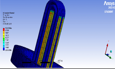
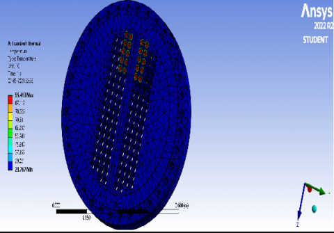
Aluminium heat exchanger - Hot water passing through tubes, as shown in Figures 5 and 6; the results are tabulated in Table 4.
Figure 5. Transient thermal analysis done on Aluminium heat exchanger - Hot water passing through tubes
Figure 6. Transient thermal analysis done on an Aluminium heat exchanger
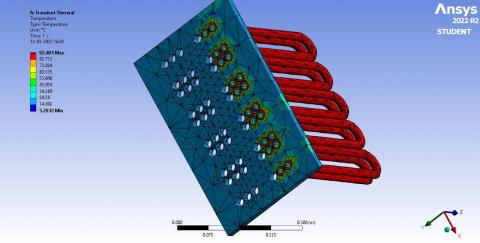
Aluminum heat exchanger - cold water passing through tubes, as shown in Figure 7, and the results are tabulated in Table 4.
Figure 7. Transient thermal analysis done on Aluminium heat exchanger - cold water passing through the tube
Table 4. Result of transient thermal analysis done on the heat exchange
|
|
ALUMINIUM |
|
|
HOT WATER |
COLD WATER |
|
|
TempMax |
368.413K |
329.416K |
|
TempMin |
293.767K |
293.834K |
From passing hot water through the aluminum tubes of the heat exchanger, it is found that a maximum temperature of 368.413 K and a minimum temperature of 293.767 K are observed using ANSYS 2022 R2 software. Similarly, by passing cold water through the aluminum tubes of the heat exchanger, it is found that a maximum temperature of 329.416 K and a minimum temperature of 293.834 K are observed.
3.4 Results of thermal analysis of redesigned heat exchanger model
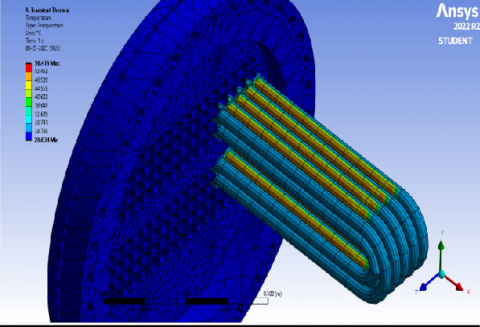
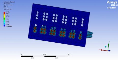
Performed transient thermal analysis on the copper heat exchanger and studied the temperature gradient acting on it. Copper heat exchanger - hot water passing through tubes, as shown in Fig; results are tabulated in Table 5. Copper heat exchanger - cold water passing through tubes as shown in Figure 9 , and results are tabulated in Table 5 .
Figure 8. Transient thermal analysis for redesigned heat exchanger - hot water passing through the tube
Figure 9. Transient thermal analysis done on copper heat exchanger - cold water passing through the tube
Table 5. Result of transient thermal analysis done on the heat exchanger
|
|
COPPER |
|
|
HOT WATER |
COLD WATER |
|
|
Temp Max |
365.401K |
323K |
|
Temp Min |
278.20K |
294.42K |
From passing hot water through the copper tubes of the heat exchanger, it is found that the maximum temperature of 365.401K and a minimum temperature of 278.2032 K are observed using Ansys 2022 R2 software. Similarly, by passing cold water through the copper tubes of the heat exchanger, it is found that the maximum temperature of 323K and a minimum temperature of 294.424 K are observed using Ansys 2022 R2 software.
Results obtained from transient thermal analysis of the heat exchanger are tabulated below in Table 6.
Table 6. Result of transient thermal analysis done on the heat exchanger
|
|
ALUMINIUM |
COPPER |
||
|
HOT WATER |
COLD WATER |
HOT WATER |
COLD WATER |
|
|
TempMax |
368.413K |
329.416K |
365.401K |
323K |
|
TempMin |
293.767K |
293.834K |
278.2032K |
294.424K |
[1] Serth RW (2007). Process heat transfer: Principles, applications and rules of thumb. Process Heat Transfer: Principles, Applications and Rules of Thumb 2007:1–680. https://doi.org/10.1016/B978-0- 12-373588-1.X5000-1.
[2] Balaji C, Srinivasan B, Gedupudi S (2020). Heat Transfer Engineering: Fundamentals and Techniques. Elsevier. https://doi.org/10.1016/B978-0-12- 818503-2.00018-6
[3] Kanchan BK, Chandan GK, Kumar J (2023). Effect of Obstacle Configuration in Sinusoidal BFSC on Hydrothermal Performance and Irreversibility Characteristics: A Numerical Study. Iranian Journal of Science and Technology - Transactions of Mechanical Engineering 2023: 1–18. https://doi.org/10.1007/S40997-023-00649- 7/METRICS
[4] Kanchan BK, Bhowmick D, Randive P (2023). Tuning the pin configuration on cold plate for better thermal management of lithium-ion battery. https://doi.org/10.1177/09544089231190176.
[5] Chang H, Jin L (2020). Preparation and heat transfer performance of steel ball phase change concrete. Journal of New Materials for Electrochemical Systems 2020;23:204–12. https://doi.org/10.14447/jnmes.v23i3.a08.
[6] Shah RK, Sekulić DP (2003). Fundamentals of Heat Exchanger Design. Fundamentals of Heat Exchanger Design, 2003. https://doi.org/10.1002/9780470172605.
[7] Rashid Ismael B, Aruna Kumari D (2014). Design and Analysis of Heat Exchanger. International Journal of Scientific Engineering and Technology Research 2014;03:4181–7.
[8] Dhavamani R, Seeniappan K, Thulasiraman M, Mani Bharathi M, Hari Prasad SM, SivanM S, et al. (2018). Thermal analysis of shell and tube heat exchanger. International Journal of Pure and Applied Mathematics 2018;119.
[9] Di Ronco A, Cammi A, Lorenzi S (2020). Preliminary analysis and design of the heat exchangers for the Molten Salt Fast Reactor. Nuclear Engineering and Technology 2020; 52:51–8. https://doi.org/10.1016/j.net.2019.07.013.
[10] Kumar S (2018). EXPERIMENTAL ANALYSIS OF SHELL AND TUBE HEAT EXCHANGER BY USING ABAQUS. Impact International Journal of Engineering Sciences 2018;7:2277–9655. https://doi.org/10.5281/zenodo.1320859.
[11] Ranganayakulu J, Rama Krishnaiah B, Vijaykumar P, Pavan B, Goud K, Sumalatha T (2018). Design And Thermal Analysis of Parallel Flow Heat Exchanger. International Journal of Advanced Technology and Innovative Research 2018;10.
[12] Sousa J, Villafañe L, Paniagua G (2014). Thermal analysis and modeling of surface heat exchangers operating in the transonic regime. Energy 2014;64:961–9. https://doi.org/10.1016/j.energy.2013.11.032.
[13] Dhavamani R, Bharathi MM, Mohan HP, Santhosh SM, Rajkamal KS (2017). Design and Fabrication of Shell and Tube Heat Exchanger. International Journal of Latest Engineering Research and Applications 2017;2.
[14] Jamshak SH, Dev Anand M, Akshay SB, Arun S, Prajeev J, Prabhakaran P (2018). Design and Analysis of a Plate Heat Exchanger in the View of Performance Improvement and Cost Reduction. vol. 7.
[15] Sharma A, Tyagi A, Kumar A (2018). Thermal Analysis of Double Pipe Heat Exchanger. vol. 13.
[16] Santhisree N, Prashanthkumar M, Priyanka G (2017). G Priyanka Thermal Analysis of Shell and Tube Heat Exchanger. International Journal of Mechanical Engineering and Technology 2017;8:596–606.
[17] Kumar Gupta R, Pawar D (2021). Design and Analysis of Shell and Tube Heat Exchanger using different tubes materials. J Emerg Technol Innov Res 2021;8.
[18] Saydam V, Parsazadeh M, Radeef M, Duan X (2019). Design and experimental analysis of a helical coil phase change heat exchanger for thermal energy storage. J Energy Storage 2019;21:9–17. https://doi.org/10.1016/j.est.2018.11.006.
[19] N L Sharma A V, Vijay Kumar G. THERMAL ANALYSIS OF SHELL AND TUBE HEAT EXCHANGER USING MAT LAB AND FLOEFD SOFTWARE. IJRET: International Journal of Research in Engineering and Technology n.d.
[20] Patel P, Paul A (2012). Thermal Analysis Of Tubular Heat Exchanger By Using Ansys. International Journal of Engineering Research & Technology 2012;1.
[21] Faraj JJ, Hussein FM, Hamad AJ (2022). Identifying of Unsteady Performance of Oil to Water Heat Exchanger Integrated with Process. International Journal of Heat and Technology 2022;40:577–82. https://doi.org/10.18280/ijht.400226.
[22] Wijayanto DS, Soenarto, Triyono MB, Prasetyo W, Widiastuti I (2021). Analysis of Longitudinal Finned Pipes in Cross-Flow Heat Exchanger. International Journal of Heat and Technology 2021;39:1909–16. https://doi.org/10.18280/ijht.390627.
[23] Wijayanto DS, Soenarto, Triyono MB, Prasetyo W, Widiastuti I (2021). Analysis of Longitudinal Finned Pipes in Cross-Flow Heat Exchanger. International Journal of Heat and Technology 2021;39:1909–16. https://doi.org/10.18280/ijht.390627.
[24] Pasupuleti RK, Bedhapudi M, Jonnala SR, Kandimalla AR (2021). Computational Analysis of Conventional and Helical Finned Shell and Tube Heat Exchanger Using ANSYS-CFD. International Journal of Heat and Technology 2021;39:1755–62. https://doi.org/10.18280/ijht.390608.