Mochamad S. Mauludin*![]() | Agung Nugroho
| Agung Nugroho![]() | Arief Hidayat
| Arief Hidayat![]() | Singgih D. Prasetyo
| Singgih D. Prasetyo![]()
© 2024 The authors. This article is published by IIETA and is licensed under the CC BY 4.0 license (http://creativecommons.org/licenses/by/4.0/).
OPEN ACCESS
The Proportional-Integral-Derivative (PID) controller is a widely used industrial feedback control algorithm that consists of proportional, integral, and derivative components. This PID control can measure process variables and calculate errors to generate accurate control signals. PID controllers are often used for DC motor speed control applications based on desired parameters. By applying artificial intelligence, PID controller performance can be improved by determining optimal values, automatically adjusting parameters, and responding quickly and accurately to changes in process variables. This article discusses the design of a DC motor PID controller for CNC machines using the MATLAB 2017a application. In this research, a numerical approach is employed using the Action Research (AR) method to enhance practitioners' methods/ways of understanding material learned in higher education. Implementing a DC motor controller with a closed loop PID controller block can reduce the rise time value in the design transfer function. The lowest settling time and the overshoot in the PID control can result in the lowest rise time value of 136,893 ms. These findings can serve as a reference for determining the appropriate tuning method to adjust the values of proportional gain, integral gain, and derivative gain in the PID control system, thereby enhancing the production effectiveness of CNC machines.
DC motor, PID Controller, AI, MATLAB
A DC motor is an electrical machine that consumes DC electrical power to produce mechanical torque [1]. The relatively high torque makes DC motors widely used, one of which is in CNC machines. The torque produced is directly proportional to the current entering the motor coil on the armature and the strength of the magnetic field that induces the armature [2]. The DC motor can drive the CNC spindle, a tool driver. The movement of the tool in a CNC machine affects the angular speed of the rotor in the DC motor [3]. The speed can be changed based on the DC motor parameter values. In this case, saturation and friction can reduce the performance of Conventional Control [4].
Motor DC is capable of providing smoother motion and can adapt to changes in load [5]. Additionally, the power output of a DC motor can be optimally regulated to prevent overheating [6]. DC motors require accurate and stable control systems to achieve maximum results with high precision. The commonly used control system method is the proportional (P), integral (I), and derivative (D) error method, commonly referred to as the PID control method. These three components achieve optimal control [7-9].
The PID controller is a widely employed feedback control algorithm in various industrial sectors. PID controllers frequently apply to motor control tasks due to their straightforward structure and easily comprehensible control algorithm [10]. Typically, controller parameters are determined through a Trial-and-error method. Several observed factors in testing results include settling time, overshoot, and rise time. The PID tuning via the Trial and Error method involves iterative adjustments of PID parameters until the desired outcomes are achieved. One drawback of this method is its requirement for significant time and effort, as it entails repetitive experimentation. Another area for improvement is its suboptimal control accuracy [11].
Another control method that can be utilized is Manual PID Tuning, which allows users to determine PID parameters while monitoring the system response in real time. The first step in employing this method is to transform the system into a mathematical model. Once the mathematical model is inputted, the PID parameters most suitable for the system are automatically computed [12]. PID Tuner generates rapid, stable, and accurate responses, making it a precious tool in designing effective controllers for various real-world applications [13]. One drawback of using this method is that users must understand the system being built so that the resulting PID parameters can function effectively [12]. Based on some limitations arising from Manual PID Tuning, an Artificial Intelligence (AI)-based PID tuning method has been developed.
Intelligent control based on Artificial Intelligence (AI) has developed a lot to improve conventional control [14, 15]. Developments can be used as educational material for academics to analyze and implement existing theories [16]. One way to design a DC motor control model is to use PID control tuned using MATLAB autotuning. This way, the electric motor can be designed on a CNC machine based on the desired needs [17]. Based on this description, this article discusses the design of a DC motor PID controller for CNC machines using the MATLAB application. Therefore, this research will conduct a comparative simulation of PID control tuning methods based on AI and numerical approaches using MATLAB. This is done to find the appropriate tuning method for adjusting the values of proportional gain, integral gain, and derivative gain in PID control, thereby enhancing the production effectiveness of CNC machines.
PID controllers measure actual process variables and compare them to targeted setpoints. Next, the controller calculates the difference between the two, known as an error. Based on this error, each PID component generates accurate control signals to correct process variables [18].
Meanwhile, Artificial Intelligence (AI) can be used to improve the performance of PID Controllers. For example, in research conducted by Denny Irawan and Pressa Perdana SS, they used an AI algorithm to tune a PID controller. Thus, AI can help determine the optimal Kp, Ki, and Kd values for the PID controller, thereby increasing control efficiency and accuracy [19]. The use of AI in PID Controllers has several primary functions [20]:
So, the relationship between PID Controllers and AI lies in how AI can be used to optimize the performance of the PID Controller. AI can help set PID Controller parameters for better and more efficient control. The use of AI (Artificial Intelligence) based PID (Proportional, Integral, Derivative) controllers using MATLAB is often used in various applications, such as temperature control and motor control. Some examples of its use: Water Temperature Control: A PID-based water temperature control module using MATLAB Simulink has been developed. In this research, system modeling and PID controller design were carried out using the Ciancone method on the Pressure Process Rig 38-714 System [21]. Learning to Design PID Control Systems: MATLAB is used to learn how to design PID control systems in universities. With MATLAB, students can see the response of various combinations of parameters with different input variations [22]. Brushless DC Motor Control (BLDC): AI-PID controller is used to obtain PID constants (Kp, Ki, Kd) and perform programming on an ASTM 32 microcontroller [23]; DC Motor Simulation: PID controller is used in DC Motor simulation using Simulink in MATLAB. Thus, AI-based PID controllers using MATLAB have various applications in industry and education. Always understand the basics of PID control and MATLAB before applying them to a natural system [24].
By tackling various issues, AI may greatly enhance PID controller performance. By utilizing methods like neural networks and fuzzy logic, it can manage intricate, nonlinear systems more skillfully. With the use of AI, parameter adjustment may be automated to reduce overshoot and settle time. Due to the lack of ideal tuning settings, conventional techniques such as Ziegler-Nichols produce closed-loop responses. AI can also manage uncertainty since it can learn from data and adjust to changes. It can help save wear and maintenance costs by lowering chatter in the control signal through optimization [25]. Artificial intelligence (AI) may improve PID controller performance, increasing their adaptability and effectiveness for a greater variety of systems.
The research method used is the Action Research (AR) method. Action research aims to improve practitioners' methods/ways of understanding material learned in higher education [26]. Action Research (AR) is a research methodology that seeks to produce knowledge and action by tackling real-world problems in participatory, collaborative, and cyclical ways. It is a type of research that works towards social or professional change and is often based on everyday issues, aiming to create practical solutions to these problems. It is hoped to increase students' understanding of PID controllers and transfer functions.
There are two common types of AR: participatory action research and practical action research. Participatory action research emphasizes that participants should be members of the study community, empowering those directly affected by the research outcomes. In this method, participants are effectively co-researchers, with their lived experiences considered formative to the research process. Practical action research focuses more on how research is conducted and is designed to address and solve specific issues.AR is often reflected in three action research models: operational (sometimes called technical), collaboration, and critical reflection [27]. AR is an interactive inquiry process that balances problem-solving actions implemented collaboratively, with data collecting and inquiry occurring amid emergent structure. AR is different in purpose, context, and significance and is a good fit for those seeking to implement systemic change [28]. Utilizing AI technology as a PID control method is highly beneficial because the parameters' boundaries can be adjusted according to changing conditions.
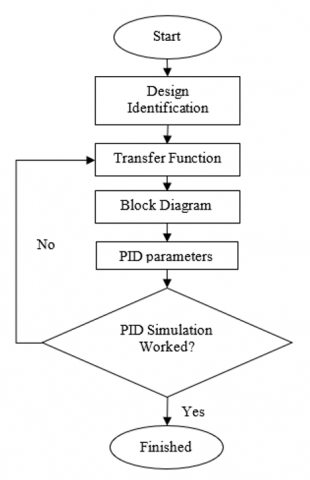
The stages in this research method include design identification, solving transfer function problems, creating block diagrams, determining PID parameters, and simulating PID performance. The research flow can be seen in Figure 1. This research uses the MATLAB 2017a software application. In this case, mastery and understanding of applications in designing machine PID controllers are essential. Using an Artificial Intelligence (AI) based Proportional-Integral-Derivative (PID) Controller using MATLAB involves several main steps [29]:
1. System Design and Modeling: The system is controlled, and the model is created using MATLAB. This involves identifying the system into a transfer function appropriate to the plant.
2. Use of AI-PID Controller: The AI-PID controller is designed and programmed using MATLAB. The AI algorithm obtains optimal PID constants (Kp, Ki, Kd).
3. Simulation: After complete design and modeling, simulation is carried out to see the system response to various parameter combinations with different input variations. This simulation helps understand how the system will respond to various conditions and how the AI-PID Controller can improve system performance.
4. Implementation on a Microcontroller: After the simulation and parameter setting are complete, the program created is implemented on a microcontroller such as ASTM 32.
Figure 1. Research flow
4.1 Design identification
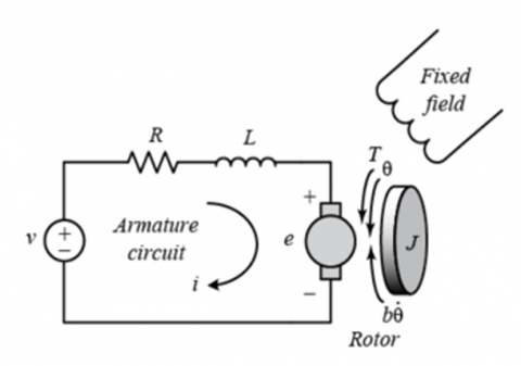
A DC electric motor has a schematic, as shown in Figure 2.
In this case study, the magnetic field strength is constant, so the motor torque is only directly proportional to the armature coil current with a constant in the relationship shown in Eq. (1).
$T=K_t i$ (1)
Figure 2. Schematic of a DC electric motor [30]
The resistance comes from the magnetic field produced by the electromagnet coil (back emf), which is proportional to the angular speed of the rotor with a constant in the relation Eq. (2).
$e=K_e \dot{\theta}$ (2)
By applying Newton's second law and Kirchoff's law to rotating objects, the system can be expressed in Eq. (3) and Eq. (4).
$J \ddot{\theta}+b \dot{\theta}=K_t i$ (3)
$L \frac{d i}{d t}+R i=V-K_e \dot{\theta}$ (4)
The design of the DC electric motor has the properties in Table 1.
Table 1. Design properties of DC electric motors [31]
|
Variable |
Mark |
|
J |
0.01 kg.m2 |
|
b |
0.1 Nms |
|
Kt |
0.01 Nm/Ampere |
|
Ke |
0.01 Vs/rad |
|
R |
8.1 Ws |
|
L |
4.05 H |
where,
J = Moment of inertia of the rotor (kg.m2)
b = Friction constant (Nms)
Kt = Torque constant (Nm/Ampere or Vs/rad)
Ke = Electric friction constant (Vs/rad)
R = Coil resistance (Ws)
L = Coil inductance (H)
V = Electric voltage on the coil (V)
i = Electric current in the coil (Amprere)
$\theta$ = Rotor rotation angle (rad)
4.2 Transfer function
Transfer Function (TF) or transfer function, namely the comparison between the output Laplace transformation and the input Laplace transformation, assuming all initial conditions are zero. The torque balance equation in Eq. (3) and Eq. (4) can be combined into an electric circuit equation for the anchor as in Eq. (5).
$R i+L \frac{d i}{d t}+K_e \frac{d \theta}{d t}=V$ (5)
Using the Laplace transformation, the current in the armature coil is as in Eq. (6).
$i(s)=\frac{s^2 J \theta(s)+s b \theta(s)}{K_t}$ (6)
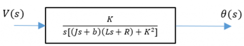
By eliminating from Eq. (6), where rotational speed is the output and voltage is the input, we obtain the transfer function as Eq. (7).
$\begin{gathered}{\left[\frac{s^2 J \theta(s)+s b \theta(s)}{K_t}\right] R+s L\left[\frac{s^2 J \theta(s)+s b \theta(s)}{K_t}\right]+s K_e \theta(s)=V(s)} \\ \frac{\left((L s+R)\left(s^2 J+b s\right)+K_t K_e\right) \theta(s)}{K_t}=V(s) \\ \frac{\theta(s)}{V(s)}=\frac{K_t}{s\left[s^2 L J+(L b+J R) s+\left(b R+K_e K_t\right)\right]}\end{gathered}$ (7)
Because then Eq. (7) can be written as Eq. (8).
$\begin{gathered}K_e=K_t=K \\ \frac{\theta(s)}{V(s)}=\frac{K}{s\left[(J s+b)(L s+R)+K^2\right]}\end{gathered}$ (8)
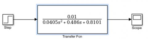
From the design properties of a DC electric motor, the transfer function has the value as in Eq. (9). In this experiment, we will also show the rotational state of the motor as its output so that the state can be obtained using dot theta integration. Therefore, we need a transfer function with s. So, the continuous-time transfer function is as follows:
$\frac{\theta(s)}{V(s)}=\frac{0.01}{0.0405 s^2+0.486 s+0.8101}$ (9)
4.3 Open loop and closed loop block diagram
The open loop block diagram of a DC electric motor design can be seen in Figure 3.
(a) sketch
(b) DC electric motor design MATLAB
Figure 3. TF open loop block diagram
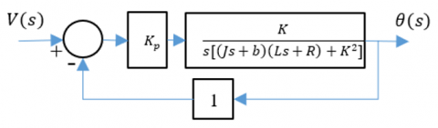
Figure 4. Closed loop block diagram of Proportional controller
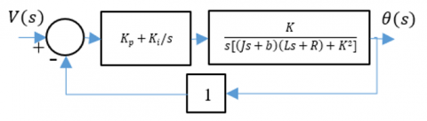
Figure 5. PI controller closed-loop block diagram
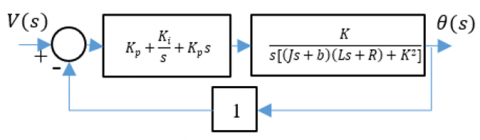
Figure 6. PID controller closed-loop block diagram
Meanwhile, the closed loop block diagram with the controller can be seen in Figures 4-6. Each is a proportional controller, PI controller, and PID controller.
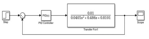
A closed loop block diagram with a PID controller system can be created using the MATLAB 2017a software application, as in Figure 7.
Figure 7. PID controller closed-loop block diagram with MATLAB
4.4 PID parameters
A sound DC motor system can demonstrate exact motor shaft movement. Another performance requirement is that the motor quickly reaches the final rotation state. In this case, the settling time is less than 2 seconds, the overshoot is less than 5%, and the error is less than 1% at steady state.
In MATLAB, PID parameter tuning for DC motors entails striking a compromise between performance attributes. Robustness, roll-off, closed-loop dynamics, and susceptibility to load perturbations are essential components. Smoother motor running is achieved by minimizing the impact of disturbances using a well-tuned PID controller. The rate at which gain diminishes with frequency or roll-off can increase noise sensitivity and enhance disturbance rejection. PID settings can directly affect closed-loop dynamics, such as overshoot, settling time, and steady-state error. For DC motors, robustness is essential since variables like resistance, inductance, and friction are only sometimes understood and can change [32]. While programs like Systune and PID Tuner can assist with tuning, the best tuning will rely on the application's particular needs.
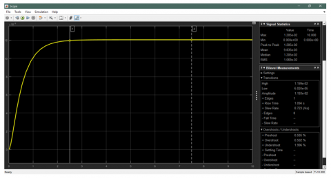
By performing the transfer function in MATLAB using a GUI by defining the numerator and enumerator as vectors and the final step parameter value 1, the open loop step response is obtained, as in Figure 8. It is found that the rise time value of the transfer function, overshoot, and amplitude is 1,094 s, 0.502%, and 0.01193. The DC motor's function meets the desired parameters in this case.
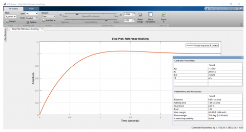
The PID controller parameters are assessed to determine the system's appropriate controller. We use the MATLAB application's trial and error method, as in Figure 9. From this method, the PID controller value is obtained, namely for each speed, based on the parameters, as in Table 2. It is found that the greater the speed, the smaller the settling time value and the greater the overshoot value. In this case, the value of the PID controller parameter is more excellent the higher the speed.
Figure 8. Open loop transient response of DC motors
Figure 9. MATLAB PID parameter values
Table 2. Result of PID controller parameter values
|
District (rad/s) |
Sett. Time (s) |
Overshoot (%) |
Kp |
Ki |
Kd |
|
2.85 |
1.84 |
4.20 |
123 |
312 |
10 |
|
5.42 |
1.17 |
3.61 |
265 |
620 |
21 |
|
8.36 |
0.97 |
3.58 |
402 |
972 |
36 |
|
11.3 |
0.74 |
3.26 |
565 |
1362 |
47 |
|
13 |
0.68 |
3.02 |
642 |
1551 |
54 |
4.5 PID Simulation
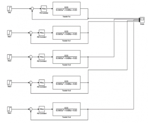
Figure 10. DC motor block diagram based on PID values
Based on the design parameters of a DC motor using a PID controller, it is applied using a block diagram. The block diagram is created based on the speed of each PID parameter. Making block diagrams using the MATLAB software application, as shown in Figure 10.
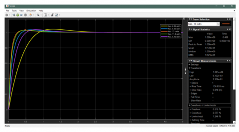
The design simulation has been successfully carried out. Simulation results using MATLAB showed that using a speed of 13 rad/s for this DC motor design had the smallest rise time value, 136,893 ms. Overshoot at a speed of 13 rad/s is 2.577%. The DC motor design simulation graph using a PID controller can be seen in Figure 11.
Figure 11. Simulations results
The DC motor control system for CNC machines, employing AI-based modeling, has been successfully executed. Employing MATLAB software, a comprehensive numerical analysis was conducted, considering the intricate parameters inherent to the PID system. With a moment of inertia registering at 0.01 kgm², quantifying the friction constant, coil resistance, and coil inductance unveiled values of 0.1 Nms, 8.1 Ws, and 4.05 H, respectively. This meticulous determination yielded rise time values for the transfer function, overshoot, and amplitude, measuring 1.094 s, 0.502%, and 0.01193, respectively. A marked reduction in the rise time value within the design transfer function was achieved through methodical optimization of the tuning system, harnessing the DC motor control system integrated with a closed-loop PID controller block. Specifically, employing a velocity of 13 rad/s on a PID controller, accompanied by a settling time of 0.68 s and an overshoot of 3.02%, yielded the minimal rise time value of 136,893 ms. These discernments offer invaluable insights for determining the apt tuning methodology to calibrate the PID control system's proportional gain, integral gain, and derivative gain. Thereby enhancing the production effectiveness of CNC machines.
The author would like to thank Wahid Hasyim University for providing the opportunity to conduct research on the Design of training modules for IoT and AI-based automatic control systems (Grant No. 234.c/Kep-UWH/VII/2023).
[1] Yaz, M., Cetin, E. (2021). Brushless direct current motor design and analysis. COJ Electronics & Communications, 2(2): 000534. http://doi.org/10.31031/COJEC.2021.02.000534
[2] Lotfy, A., Kaveh, M., Mosavi, M.R., Rahmati, A.R. (2020). An enhanced fuzzy controller based on improved genetic algorithm for speed control of DC motors. Analog Integrated Circuits and Signal Processing, 105: 141-155. https://doi.org/10.1007/s10470-020-01599-9
[3] Shi, Y., Fan, L., Meng, D., Cheng, Z. (2021). Matlab/Simulink based modeling and simulation of motorized spindle drive system. In 2021 40th Chinese Control Conference, Shanghai, China, pp. 6761-6765. https://doi.org/10.23919/CCC52363.2021.9549519
[4] Lavanya, A., Revathi, S., Sivakumaran, N., Rajkumar, K. (2023). Control of feed drives in CNC Machine tools using artificial immune adaptive strategy. In Artificial Intelligence and Cyber Security in Industry 4.0, pp. 237-251. https://doi.org/10.1007/978-981-99-2115-7_10
[5] Frayyeh, H.F., Mukhlif, M.A., Abbood, A.M., Keream, S.S. (2019). Speed control of direct current motor using mechanical characteristics. Journal of Southwest Jiaotong University, 54(4): 25. https://doi.org/10.35741/issn.0258-2724.54.4.25
[6] Nugroho, N., Agustina, S. (2015). Analisa motor DC (Direct Current) sebagai penggerak mobil listrik. Jurnal Mikrotiga, 2(1): 28-34.
[7] Shi, G., Li, D., Ding, Y., Chen, Y. Q. (2022). Desired dynamic equational proportional-integral-derivative controller design based on probabilistic robustness. International Journal of Robust and Nonlinear Control, 32(18): 9556-9592. https://doi.org/10.1002/rnc.5667
[8] Mauludin, M.S., Kurniawan, A. (2013). Perancangan trainer PID Analog untuk mengatur kecepatan putaran motor DC. Prosiding Seminar Sains Nasional dan Teknologi, 1(1): 116-123. http://doi.org/10.36499/psnst.v1i1.731
[9] Mauludin, M.S., Wijanarko, R., Budiyanto, N.E. (2014). Simulasi kontrol PID untuk mengatur putaran motor AC. Prosiding Seminar Sains Nasional Dan Teknologi, 1(1): 23-28. http://doi.org/10.36499/psnst.v1i1.1020
[10] Borase, R.P., Maghade, D.K., Sondkar, S.Y., Pawar, S.N. (2021). A review of PID control, tuning methods and applications. International Journal of Dynamics and Control, 9: 818-827. https://doi.org/10.1007/s40435-020-00665-4
[11] Muhammad, R.D., Dwi, A., Andi, I., Imam, R. (2015). Desain optimal kontroler PID motor DC menggunakan cuckoo search algorithm. Prosiding SENTIA 2015 – Politeknik Negeri Malang, 7: 121-126.
[12] Saputra, D., Ma’arif, A., Maghfiroh, H., Chotikunnan, P., Rahmadhia, S.N. (2023). Design and application of PLC-based speed control for DC motor using PID with identification system and MATLAB tuner. International Journal of Robotics and Control Systems, 3(2): 233-244. https://doi.org/10.31763/ijrcs.v3i2.775
[13] Budin, N.S.E., Osman, K. (2022). Modelling and proportional-integral-derivative controller design for position analysis of the 3-degree of freedom. Indonesian Journal of Electrical Engineering and Computer Science, 27(1): 62-70. https://doi.org/10.11591/ijeecs.v27.i1.pp62-70
[14] Ragaveena, S., Shirly Edward, A., Surendran, U. (2021). Smart controlled environment agriculture methods: A holistic review. Reviews in Environmental Science and Bio/Technology, 20(4): 887-913. https://doi.org/10.1007/s11157-021-09591-z
[15] Gandhi, M.M., Solanki, D.S., Daptardar, R.S., Baloorkar, N.S. (2020). Smart control of traffic light using artificial intelligence. In 2020 5th IEEE International Conference on Recent Advances and Innovations in Engineering (ICRAIE), Jaipur, India, pp. 1-6. https://doi.org/10.1109/ICRAIE51050.2020.9358334
[16] Barus, I.R.G., Simanjuntak, M.B., Resmayasari, I. (2021). Reading literacies through evieta-based learning material: students’perceptions (Study case taken from vocational school–IPB university). Journal of Advanced English Studies, 4(1): 15-20. http://doi.org/10.47354/jaes.v4i1.98
[17] Mohamed, M.E.A., Guo, Y. (2019). Separately excited DC motor speed tracking control using adaptive neuro-fuzzy inference system based on genetic algorithm particle swarm optimization and fuzzy autotuning PID. IOP Conference Series: Earth and Environmental Science, 300(4): 042114. http://doi.org/10.1088/1755-1315/300/4/042114
[18] Issa, M., Elbaset, A.A., Hassanien, A.E., Ziedan, I. (2019). PID controller tuning parameters using meta-heuristics algorithms: Comparative analysis. Machine Learning Paradigms: Theory and Application, pp. 413-430. https://doi.org/10.1007/978-3-030-02357-7_20
[19] Kusuma, D.H., Ali, M., Sutantra, N. (2016). The comparison of optimization for active steering control on vehicle using PID controller based on artificial intelligence techniques. In 2016 International Seminar on Application for Technology of Information and Communication (ISemantic), pp. 18-22. https://doi.org/10.1109/ISEMANTIC.2016.7873803
[20] Dubey, V., Goud, H., Sharma, P.C. (2022). Role of PID control techniques in process control system: A review. Data Engineering for Smart Systems, pp. 659-670. https://doi.org/10.1007/978-981-16-2641-8_62
[21] Wahyudhi, A. (2019). Perancangan pengendali LQR-PID untuk mengendalikan temperatur dan kelembaban udara relatif pada sistem ruang pendingin jamur merang. Doctoral dissertation, Universitas Islam Negeri Sultan Syarif Kasim Riau.
[22] Wang, L. (2020). PID Control System Design and Automatic Tuning Using MATLAB/Simulink. John Wiley & Sons.
[23] Mahmud, M., Motakabber, S.M.A., Alam, A.Z., Nordin, A.N. (2020). Control BLDC motor speed using PID controller. International Journal of Advanced Computer Science and Applications, 11(3): 477-481. https://doi.org/10.14569/IJACSA.2020.0110359
[24] Ma'arif, A., Setiawan, N.R. (2021). Control of DC motor using integral state feedback and comparison with PID: Simulation and arduino implementation. Journal of Robotics and Control (JRC), 2(5): 456-461. https://doi.org/10.18196/jrc.25122
[25] Schöning, J., Pfisterer, H.J. (2023). Safe and trustful AI for closed-loop control systems. Electronics, 12(16): 3489. https://doi.org/10.3390/electronics12163489
[26] Yang, J. (2020). Participatory action research: Promoting partnership between a social work team and mothers of hemophiliac children. Action Research, 18(1): 102-124. https://doi.org/10.1177/1476750319895311
[27] Siponen, M., Baskerville, R.L. (2018). Intervention effect rates as a path to research relevance: Information systems security example. Journal of the Association for information Systems, 19(4): 247-265. https://doi.org/10.17705/1jais.00491
[28] Sundarakani, B., Ajaykumar, A., Gunasekaran, A. (2021). Big data driven supply chain design and applications for blockchain: An action research using case study approach. Omega, 102: 102452. https://doi.org/10.1016/j.omega.2021.102452
[29] Singh, A. (2023). Some studies on artificial intelligence based fractional order PID controller. Doctoral dissertation, Delhi Technological University.
[30] Azar, A T., Ali, N., Makarem, S., Diab, M.K., Ammar, H.H. (2020). Design and implementation of a ball and beam PID control system based on metaheuristic techniques. In Proceedings of the International Conference on Advanced Intelligent Systems and Informatics 2019, Cairo, Egypt, pp. 313-325. https://doi.org/10.1007/978-3-030-31129-2_29
[31] DC Motor Control Design. Maple Help. https://www.maplesoft.com/support/help/maple/view.aspx?path=applications%2FDCMotor.
[32] Prabakar, K. (2015). Gain tuning of proportional integral controller based on multiobjective optimization and controller hardware-in-loop microgrid setup. Doctoral dissertations, University of Tennessee.