Rafik Dembri*![]() | Lazhar Rahmani
| Lazhar Rahmani![]() | Badreddine Babes
| Badreddine Babes![]() | Idris Azizi
| Idris Azizi![]()
© 2024 The authors. This article is published by IIETA and is licensed under the CC BY 4.0 license (http://creativecommons.org/licenses/by/4.0/).
OPEN ACCESS
This paper introduces an innovative control strategy for wind turbine systems (WTS) based on doubly fed induction generators (DFIGs). The strategy employs a fractional-order fuzzy PD+I (FO Fuzzy PD+I) regulator, which is optimized using the social spider optimizer (SSO) algorithm. This approach marks a significant advancement in DFIG control compared to existing methods that rely on traditional PI regulators. The proposed FO Fuzzy PD+I regulator leverages the combined strengths of fuzzy logic and fractional-order control, resulting in superior performance and robustness in DFIG current control. It effectively addresses uncertainties in DFIG parameters and wind speed variations, while enabling independent active and reactive power regulation for enhanced grid integration and power quality management. The efficacy of the proposed approach is validated through simulations across diverse operational scenarios, encompassing step changes in active power reference and rapid fluctuations in wind speed. The optimized FO Fuzzy PD+I regulator consistently outperforms the traditional PI regulator in terms of integral time absolute error (ITAE), peak overshoot, maximum undershoot, settling time, and total harmonic distortion (THD) of DFIG current. This research represents a significant contribution to the field of DFIG control, offering a more effective and robust solution for wind turbine operation, ultimately leading to improved power quality and grid integration capabilities.
doubly-fed induction generator (DFIG), wind turbine system (WTS), fractional-order fuzzy PD+I (FO Fuzzy PD+I) regulator, direct vector control (DVC), social spider optimization (SSO) technique
Growing concerns about climate change have fueled the rise of renewable energy, with wind power emerging as a key player. Due to its effectiveness in battling global warming, wind energy is becoming a critical alternative to fossil fuels [1]. The DFIG is a widely used electrical machine in wind WTS due to its versatility in regulating both active and reactive power. It comprises a stator and a rotor, with the stator directly connected to the grid and the rotor connected via converters known as the rotor side converter (RSC) and the grid side converter (GSC) [2, 3]. The RSC controls active and reactive power injected into the grid, while the GSC regulates the DC link voltage and ensures unity power factor operation [4]. By utilizing optimal tip speed ratio (OPTSR) to design the maximum power point tracking (MPPT) controller, maximum power extraction from wind energy is achieved [5-7]. Various control strategies, including direct vector control (DVC), are employed to enhance energy quality and minimize current and power ripples. However, the implementation of DVC using proportional-integral (PI) regulators faces challenges such as active power ripples and slow dynamic response [8]. Adjusting PI regulator parameters becomes crucial for different operating points and wind speeds, as fixed parameters may affect efficiency and power decoupling [9]. Alternative regulators like hysteresis, sliding mode, predictive, and synergetic regulators have been proposed to overcome these challenges, albeit requiring skilled parameter tuning and time for adjustment [10-13]. Notably, previous research predominantly focuses on DFIG systems with low power outputs, ranging from 1 KW to 50 KW.
Fractional-order (FO) calculus uses real number order of derivation and integration instead of the integer number, which enables it to accurately define the system's dynamics [14-16]. Over the last 10 years, the fractional-order PID (FO-PID) regulator has become increasingly popular for a wide range of industrial control problems due to its simplicity and increased level of freedom. The FO-PID regulator provides better closed-loop performance and greater robustness than the PID regulator. Although, FO-PID regulators extend the capabilities of traditional PID controllers, they are predominantly employed in the form of PIλDµ, wherein λ signifies the fractional order of the integral component and μ denotes the fractional order of the derivative component. This configuration offers additional degrees of freedom, thereby enhancing the flexibility to fine-tune the dynamic characteristics of a system [17-19].
The application of FO-PID regulator within different RESs is presented in [20-23]. Nevertheless, notwithstanding the promising outcomes achieved by FO-PID regulators in the studies mentioned earlier, the implementation of the FO-PID regulator on DFIG is not effective enough due to its complex nonlinear structures and fine-tuning of the FO-PID gains [24]. Recent studies have shown that combining a Fuzzy logic regulator with a FO-PID regulator can lead to a more flexible control architecture [25-27]. Therefore, combining Fuzzy and FO-PID regulators is recommended to boost the efficiency of DFIG. The combination of these two regulators is known as the Fractional-order Fuzzy PID (FO Fuzzy PID) regulator. The FO Fuzzy PID regulator stands out as a compelling technique recommended for addressing the complexities of delayed nonlinear processes and open-loop unstable processes with time delays [28]. This combination has yielded several advantages, including the capacity to adjust regulator parameters without knowing the system's precise model, fast response with increased regulator robustness, and managing severe perturbations such as parameter changes and RES fluctuations [29].
Moreover, the FO Fuzzy PID has been designed with diverse configurations in the literature. Further, a parallel combination of fuzzy FO-PI and fuzzy FO-PD regulators were given in paper [30] utilizing the FO fuzzy PI+PD regulator, in paper [31] utilizing FO fuzzy P+ID regulator, and in paper [32] utilizing the FO fuzzy PI+D regulator. The study conducted in reference [33] delves into the examination of the FO fuzzy PD regulator, focusing on its digital implementation nuances and robustness characteristics. Likewise, an improved FO Fuzzy PID regulator with the help of antlion optimizer (ALO) was proposed in paper [34] for Buck converter. Moreover, numerous combination and cascade structures have also been reported in the literature for using the FO Fuzzy PID regulator [35].
However, accurate tuning methodology is necessary for several parameters, particularly for FO Fuzzy PID regulators. As a result, the choice of an optimization technique raises many challenges. Various optimization methods like Genetic Algorithms (GA), Harmony Search (HS), Particle Swarm Optimization (PSO), Ant Colony Optimizer (ACO), and Gravitational Search Algorithm (GSA)have been successfully used to drive the most suitable gains for FO Fuzzy PID regulator and yield effective dynamic performance improvement in the system [36-40]. Similarly, the Differential Evolution Optimizer (DEO) was used to optimize the FO Fuzzy PID gains in [41].
Meanwhile, the optimizers above have some drawbacks, such as long computational time, slow convergence, low precision, saturation, complex parameter setting and lack of robustness. Nevertheless, these features have encouraged the use of the Social Spider optimizer (SSO) to tackle a diverse array of engineering applications across different fields, such as the design of FO Fuzzy regulator [42], computer vision [43], micro-grid control [44], congestion control [45], and anti-islanding protection [46].
Hence, for our evolutionary optimization technique, we utilize the SSO algorithm proposed by Erik Cuevas to address the shortcomings of the previous optimizers. SSO is a newly suggested population-based metahuristic algorithm inspired by behavior of social spiders, which collaborate to build webs and share information about the position. The SSO works by having a population of spiders that search for the best solution to a particular problem. It has been shown in the study [42] that SSO is significantly superior to existing optimization techniques.
The objective of this study is to develop, analyze, and assess the efficacy of a FO Fuzzy PD+I regulator via a recent optimizer using the SSO algorithm to directly and independently regulate the DFIG's active and reactive power. So, the SSO is responsible for determining the unknown parameters of the designed FO Fuzzy PD+I regulator so that the integral time absolute error of the DFIG current is minimized. To our knowledge, FO Fuzzy PD+I regulator based on a SSO algorithm has not already been utilized to control DFIG-based WTS. Hence, to verify the attainability of the proposed performance, our focus in this study is directed towards the internal current control loop. The detailed explanation of the designed DVC strategy will be provided in the subsequent sections of the paper. As mentioned earlier, the contributions of this research can be succinctly outlined as follows:
The remainder of this article is organized into six sections. Section 2 provides an introduction to DFIG-Based WTS. Section 3 outlines the proposed FO Fuzzy PD+I regulator. Section 4 delves into the SSO algorithm. The simulations tests and results are presented in detail in Section 5 including comparison with a PI regulator and a parameter variation test. Finally, some conclusions and remarks about the dynamic performance of the optimized FO Fuzzy PD+I regulator are made in Section 6.
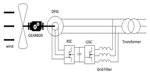
The intricate setup employed in this article is shown in Figure 1. Here, the stator windings are directly interconnected with the three-phase power grid, while the rotor windings are linked to the prime mover via the AC-DC-AC converter [5]. This converter furnishes three-phase rotor excitation power, offering adjustability in phase, frequency, and amplitude, and ensures bidirectional flow of slip power.
Figure 1. Configuration of DFIG-based WTS
2.1 DFIG model and control theory
The comprehensive mathematical representation of the DFIG within the rotating coordinate system of Park (d-q) encompasses four state equations. These equations encapsulate the mechanical dynamics, rotor and stator voltages, rotor and stator flux, as well as rotor and stator powers, denoted by Eqs. (1) to (4) respectively [47]:
$\left\{\begin{array}{c}J \frac{d}{d t} \Omega_r+f_r \Omega_r=T_e-T_r \\ T_e=\frac{3}{2} P \frac{M}{L_r}\left(\psi_{q s} I_{d r}-\psi_{d s} I_{q r}\right)\end{array}\right.$ (1)
$\left\{\begin{array}{l}V_{d r}=R_r I_{d r}+\frac{d}{d t} \psi_{d r}-\left(\omega_{o b s}-\omega_m\right) \psi_{q r} \\ V_{q r}=R_r I_{q r}+\frac{d}{d t} \psi_{q r}+\left(\omega_{o b s}-\omega_m\right) \psi_{d r} \\ V_{d s}=R_s I_{d s}+\frac{d}{d t} \psi_{d s}-\omega_{o b s} \psi_{q s} \\ V_{q s}=R_s I_{q s}+\frac{d}{d t} \psi_{q s}+\omega_{o b s} \psi_{d s}\end{array}\right.$ (2)
$\left\{\begin{array}{l}\psi_{d r}=L_r I_{d r}+M I_{d s} \\ \psi_{q r}=L_r I_{q r}+M I_{q s} \\ \psi_{d s}=L_s I_{d s}+M I_{d r} \\ \psi_{q s}=L_s I_{q s}+M I_{q r}\end{array}\right.$ (3)
$\left\{\begin{array}{l}P_s=\frac{3}{2}\left(V_{d s} I_{d s}+V_{q s} I_{q s}\right) \\ Q_r=\frac{3}{2}\left(V_{q s} I_{d s}-V_{d s} I_{q s}\right)\end{array}\right.$ (4)
Table 1. The symbols in the DFIG mathematical model
|
Vds, Vqs |
(d-q) component of stator voltage |
|
Ids, Iqs |
(d-q) component of stator current |
|
Vdr, Vqr |
(d-q) component of rotor voltage |
|
Idr, Iqr |
(d-q) component of rotor current |
|
Ψds, Ψqs |
(d-q) component of stator flux |
|
Ψdr , Ψqr |
(d-q) component of rotor flux |
|
Ls, Lr |
The stator and the rotor winding inductors |
|
Rs, Rr |
The stator and the rotor winding resistors |
|
M |
Mutual inductance |
|
ωs, ωr |
The stator and the rotor angular velocity |
|
Ps , Pr |
The active power of the rotor and stator |
|
Qs , Qr |
The reactive power of the stator and rotor |
|
P |
Number of pole pairs |
|
J |
Total inertia |
|
f |
Total external damping |
|
Tem |
Generator torque |
|
Tr |
Aerodynamic torque |
Table 1 provides a comprehensive list of symbols used in the mathematical model of DFIG, along with their corresponding descriptions.
This section elucidates how the previously derived equations can be effectively applied to autonomously regulate the reactive and active powers of the DFIG, without impacting the control of the RSC current. Two prominent vector control techniques employed for the RSC, as discussed in the literature [5, 47] are the Stator Flux Oriented (SFO) and Stator Voltage Oriented (SVO) methods. In the SFO approach, control actions occur within a rotating reference frame dq, with the d-axis aligned with the stator flux. Conversely, in SVO, the d-axis aligns with the stator voltage. This study primarily concentrates on SFO, owing to its widespread adoption in DFIG control strategies. It involves the conversion of three-phase voltages, currents, and fluxes into a rotating reference frame, followed by the implementation of cascaded control techniques to track stator active and reactive power. This alignment decision results in the direct rotor current being proportionate to the stator reactive power, while the quadrature rotor current is proportional to the active stator power, as elucidated in subsequent discussions. In the SFO reference frame theory, the stator flux $\Psi_s$ is associated with the d-axis of the synchronous frame, which gives us the advantage that:
$\psi_{d s}=\psi_s$ (5)
$\psi_{q s}=0$ (6)
Assuming that the stator flux stays constant because of the AC voltage from the grid provides a constant voltage to the stator [5], and by neglecting the stator resistance drop. We can simplify the stator voltage amplitude as:
$V_{d s}=0$ (7)
$V_{q s}=V_s=\omega_s \psi_s=$ constant (8)
$\frac{d\left|\psi_s\right|}{d t}=0$ (9)
The following equations are obtained when applied to Eqs. (1)-(9):
$\left\{\begin{array}{c}V_{d r}=R_r I_{d r}+\sigma L_r \frac{d I_{d r}}{d t}-g \omega_s \sigma L_r I_{q r} \\ V_{q r}=R_r I_{q r}+\sigma L_r \frac{d I_{q r}}{d t}-\sigma g \omega_s I_{d r}+g \frac{M V_s}{L_s}\end{array}\right.$ (10)
where:
$\sigma=1-\frac{M}{L_r L_s}, g=\frac{\omega_s-\omega_r}{\omega_s}$
The stator power equations may be defined as:
$\left\{\begin{array}{c}P_s=-\frac{3}{2} p \frac{M V_s}{L_s} I_{q r}=K_p I_{q r} \\ Q_s=\frac{3}{2} \frac{V_s^2}{\omega_s L_s}-\frac{3}{2} \frac{M V_s}{L_s} I_{d r}=K_Q\left(I_{d r}-\frac{V_s}{\omega_s L_s}\right)\end{array}\right.$ (11)
where, g indicates the generator slip.
The following equation illustrates the correlation between the rotor current and generator torque.
$T_e=\frac{P_s}{\omega_s}=-\frac{M V_s}{\omega_s L_s} I_{q r}$ (12)
According to Eq. (11), the stator reactive and active powers can be regulated separately by controlling the quadrature and the direct rotor currents $I_{q r}$ and $I_{d r}$, respectively. A PI regulator can be used to control the rotor current for each rotor current component $(d-q)$. The reference values of the direct and quadrature rotor currents $I_{d r}{ }^*$ and $I_{q r}{ }^*$ can be determined through the outer loops. Additionally, cross terms of (10) can be added to the output of each current regulator as an aid.
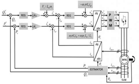
Within this configuration, as illustrated in Figure 2, it results in a cascade structure of two equivalent closed-loop systems. The inner loop controls the rotor currents, while the outer loop exclusively manages the stator's active and reactive power.
The PI regulators are employed to control the rotor currents ($I_{d r}-I_{q r}$), as demonstrated in (13):
$\left\{\begin{array}{l}V_{q r}^*=k_{p_{-} I_{d r}} \cdot\left(I_{d r}^*-I_{d r}\right)+k_{i_{-} I_{d r}} \cdot \int\left(I_{d r}^*-I_{d r}\right) d t \\ V_{d r}^*=k_{p_{-} I_{q r}} \cdot\left(I_{q r}^*-I_{q r}\right)+k_{i_{-} I_{q r}} \cdot \int\left(I_{q r}^*-I_{q r}\right) d t\end{array}\right.$ (13)
Figure 2. Direct vector control of the DFIG-based WTS
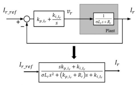
Figure 3 depicts the convergence of both axes towards identical characteristics, with their plant being simplified to a first-order transfer function. Additionally, the equivalent closed-loop systems of both current loops are portrayed as second-order systems with two poles and a zero, which can be manipulated using classical control theory by selecting suitable gains for the PI regulators. Various techniques for tuning PI controllers are extensively documented in the literature, such as the Ziegler-Nichols method, the pole placement method, and the Bode plot method [5].
Figure 3. The equivalent closed-loop systems of current loops
Again, a simple PI regulator can control the stator active and reactive power as described by (14):
$\left\{\begin{array}{l}I_{q r}^*=k_{p_{-} P_s} \cdot\left(P_s^*-P_s\right)+k_{i_{-} P_s} \cdot \int\left(P_s^*-P_s\right) d t \\ I_{d r}^*=k_{p_{-} Q_s} \cdot\left(Q_s^*-Q_s\right)+k_{i_{-} P_s} \cdot \int\left(Q_s^*-Q_s\right) d t\end{array}\right.$ (14)
As it is presented in (14), the $d$-axis rotor current reference $I_{r d}{ }^*$ is obtained by the output of the stator active power regulator, and the $q$-axis rotor current reference $I_{r q}{ }^*$ is generated by the output of stator reactive power regulator.
There are two additional estimators with a similar structure in the proposed DVC method. The first is used to predict Ps value, while the second predicts the $Q_s$. The following are the predicted stator powers:
$\left\{\begin{array}{c}P_s=-\frac{3}{2} \frac{M}{\sigma L_r L_s} \cdot\left(\psi_{r \alpha} V_s\right) \\ Q_s=-\frac{3}{2}\left(\frac{V_s}{\sigma L_s} \cdot \psi_{r \beta}-\frac{V_s M}{\sigma L_r L_s} \cdot \psi_{r \alpha}\right)\end{array}\right.$ (15)
Concisely, Figure 4 depicts the overall control architecture of a DFIG-based WTS. The composite control system consists of the stator power regulators, the direct and quadrature rotor current regulators, and the MPPT controller.
Figure 4. Description of the DFIG control system
In this part, we introduce the utilization of a Fractional Order Fuzzy Proportional-Derivative-Integral regulator for the efficient and robust control of a DFIG, deviating from the traditional use of a PI regulator typically employed for the internal current loop.
3.1 Fractional order calculus
Fractional calculus stands as a comprehensive extension of conventional differentiation and integration methodologies, introducing the concept of non-integer orders for the primary operator ${ }_a D_b{ }^\alpha$. Here, $\mathrm{a}$ and $\mathrm{b}$ delineate the upper and lower limits of the operator, while $\alpha$ represents the order of integration or differentiation $(\alpha \in R)[17,18]$. The notation ${ }_a D_b{ }^\alpha$ encapsulates both the fractional integral and the fractional derivative simultaneously, presenting a unified framework for addressing complex mathematical operations. It is defined as follows:
$a D_b^a=\left\{\begin{array}{c}\frac{d^\alpha}{d t^\alpha} R(\alpha)>0 \\ 1 R(\alpha)=0 \\ \int_a^b(d t)^{-\alpha} R(\alpha)<0\end{array}\right.$ (16)
Riemann Liouville's (RL) differ-integral is utilized in this paper to implement the proposed control method as defined in the following equation for a function f(t):
$a D_b^a f(t)=\frac{1}{\Gamma(m-a)} \frac{d^m}{d t^m} \int_a^b \frac{f(\tau)}{(t-\tau)^{a+1-m}} d \tau$ (17)
where, $m$ is the integer part of $a, f(t)$ is the applied function, and $\Gamma$ is Euler's gamma function of $x$.
$\Gamma(x)=\int_0^{\infty} e^{-t} t^{x-1} d t$ (18)
3.2 Fractional order-based PID regulator
The fractional-order PID regulator (FO-PID) is a generalized form of the integer-order PID regulator. This means that it appears as the PID regulator when plotted from point to plane. However, it can provide an extra degree of freedom through its integral and derivative orders and regulator gains [37]. The transfer function for this type of regulator can be expressed in mathematical form as follows:
$G_C(s)=\frac{U(s)}{E(s)}=K_p+\frac{K_i}{s^\lambda}+K_d s^\mu$ (19)
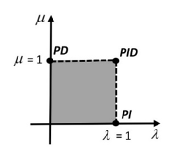
where, $\mu$ is the fractional component of derivative parts, and $\lambda$ is the fractional component of integral parts, and $G_c(s)$ is the transfer function of the FO-PID regulator, $K_p, K_i$ and $K_d$ are respectively corresponding derivative, proportional, and integral gains of the FO-PID regulator. As shown in Figure 5, the PID and FO-PID regulator's orders are displayed on a schematic diagram, with the differentiator's order $(\mu)$ described along the vertical axis. The integrator's order $(\lambda)$ may change along the horizontal axis.
Figure 5. Representation of FO Fuzzy PD+I regulator
3.3 Structure of the FO fuzzy PD+I regulator
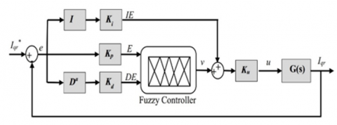
Fuzzy logic control (FLC) employs non-linear empirical rules to mimic human-like decision-making, bypassing the need for complex mathematical designs. Recent research has shown that integrating FLC with fractional-order operators for integration and differentiation can increase the system's degrees of freedom and provide additional flexibility in designing classical FLC-based PID regulators [28]. The synergy between FLC and fractional-order operators capitalizes on their respective strengths. FLC offers a robust approach for managing nonlinearities and uncertainties at a conceptual level, while fractional-order operators offer precise control over system dynamics, facilitating more accurate modeling and control. By combining FLC with fractional-order operators, the control system gains enhanced adaptability and robustness in uncertain environments. Fuzzy logic excels at handling large uncertainties or vague information, while fractional-order control adeptly captures subtle dynamics and optimizes control actions to achieve desired performance levels [28]. In recent years, numerous structures of the FO Fuzzy PD+I regulator have undergone extensive development [48]. In the proposed framework, the conventional derivative order rate of the error input to the Fuzzy Logic Controller is substituted with its fractional order equivalent (Dα). This substitution incorporates an integrator and a summation unit at the output of the FLC to yield the total regulator output, as depicted in Figure 6. This particular regulator structure has been considered as the most successful solution among FO-Fuzzy structures in previous applications [28].
Figure 6. The configuration of FO fuzzy PD+I regulator
The transfer function of the DFIG is given by:
$G(s)=\frac{1}{\sigma L_r s+R_r}$ (20)
The control law of the suggested FO Fuzzy PD+I regulator in time domain is given by:
$\begin{aligned} & U_{F O F u z z y P D+I}(t) =U_{\text {FOFuzzyPD }}(t) \cdot K_u+U_{F O I}(t) \cdot K_u =K_u \cdot\left[f\left(K_p e, K_d D^a e\right)+K_i I e\right] \end{aligned}$ (21)
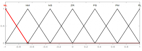
In this new kind of FO Fuzzy PD+I regulator the values of the order ($\alpha$) along with scaling coefficients ($K_i, K_p, K_d, K_u$) are the optimization variables that need to be calibrated by using the SSO algorithm. The proposed FO Fuzzy PD+I regulator employs a sophisticated two-dimensional linear rule base (as outlined in Table 2) that encompasses error, fractional rate of error, and Fuzzy output. This rule base is meticulously designed to leverage regular triangular membership functions (illustrated in Figure 7) and employs Mamdani type inferencing, reflecting a nuanced approach to system control and regulation.
Table 2. The fuzzy rule base
|
E/DE |
NL |
NM |
NS |
ZR |
PS |
PM |
PL |
|
NL |
NL |
NL |
NL |
NL |
NM |
NS |
ZR |
|
NM |
NL |
NL |
NL |
NM |
NS |
ZR |
PS |
|
NS |
NL |
NL |
NM |
NS |
ZR |
PS |
PM |
|
ZR |
NL |
NM |
NS |
ZR |
PS |
PM |
PL |
|
PS |
NM |
NS |
ZR |
PS |
PM |
PL |
PL |
|
PM |
NS |
ZR |
PS |
PM |
PL |
PL |
PL |
|
PL |
ZR |
PS |
PM |
PL |
PL |
PL |
PL |
Figure 7. Membership functions for inputs and output
The fuzzy IF-THEN rules of FO Fuzzy PD+I regulator are written as follows:
$R^{(l)}:$ IF e is $A_1^l$ and $\dot{e}$ is $A_2^l$ THEN y is $B_1^l$
where, $A_1^l,(i=1,2)$ and $B_1^l$ indicate the linguistic variables of the inputs and output of the FLC. The variable $l=$ $1,2, \ldots, m$ signifies the count of fuzzy IF-THEN rules. Seven triangular membership functions are applied to each input and output variable, resulting in a total of (7×7) rules listed in Table 1. The Linguistic variables are defined by following letters P, N M, S, ZR, S, M and L symbolize Positive, Negative, Zero, Small, Medium and Large respectively. As a result, the main rule using Table 1 might be as follows:
IF DE is equal to PS and E is equal to ZR, THEN ν must be PS.
Based on this rule, the control strategy is inferred to respond when the error derivative is " Positive Small " and the error is classified as "Zero," leading to an output characterized as " Positive Small " as well. The crisp value derived from the Fuzzy output is determined using the center of gravity (CoG) method during defuzzification. In an endeavor to enhance the overall closed-loop performance of a DFIG-based wind turbine system, the present study emphasizes the adjustment of the fractional rate of error ($\alpha$), while preserving the integrity of the rule base and the structure of membership functions unchanged. This targeted adjustment aims to fine-tune the system's response dynamics, thereby optimizing its operational efficiency and stability.
The SSO is a completely new swarm optimization method introduced by Cuevas et al. [42]. He studied the nature of social-spider colonies and their cooperative behavior when developing this intelligent algorithm. Furthermore, the SSO scheme underwent experimental evaluation across three distinct classes of systems: higher-order plants, non-minimum systems, and dynamic fractional systems. It was juxtaposed against other akin evolutionary approaches including GA, HS, PSO and GSA) These experiments conclusively showcased that The proposed SSO method demonstrates superior performance in terms of both solution accuracy and convergence compared to other techniques. Nowadays, there are many publications dedicated to exploring modifications, improvements, or applications of SSO for solving various intricate optimization problems. [42-46]. At the heart of the SSO algorithm lies a sophisticated framework comprising two fundamental search agents: the social spiders and the communal web. These spiders are intricately subdivided into distinct genders, delineating a structured hierarchy within the algorithm. Within the SSO methodology, the placement of each solution within the vast search space mirrors the spatial arrangement of spiders within the communal web. Furthermore, each spider is imbued with a weighted significance, meticulously determined by the fitness value of the corresponding solution, as meticulously evaluated by the discerning social spider. The initialization phase of the SSO algorithm commences with the establishment of a population, denoted as S, comprising an ensemble of N spider locations representing diverse solutions. This diverse assembly encompasses both female (fi) and male (mi) spiders, thereby encapsulating the comprehensive breadth of the search space.
Given that female spiders typically constitute a larger proportion than males in authentic spider societies (approximately $70-90 \%$ ), we opted to randomly designate the number of female spiders, denoted as $N_f$, to comprise approximately $85 \%$ of the total population, $N$ [42]. As such, Eqs. (22) and (23) are used to determine $N_f$ and $N_m$:
$N_f=$ floor $[N \cdot(0.9-0.25 . \operatorname{rand}(0.1))]$ (22)
$N_m=N-N_f$ (23)
In this context, "rand" denotes a randomly generated value ranging from 0 to 1 , while "floor(.)" function converts a real number to the nearest integer value Consequently, $N$ elements compose the entire population $S=\{s 1, s 2 \ldots, s N\}$, which is then divided into the sub-groups male spiders $M=$ $\{m 1, m 2, \ldots, m N m\}$ and female spider $F=$ $\{f 1, f 2, \ldots, f N f\}$, such that: $S=\{s 1=f 1, s 2=$ $f 2, \ldots, s N f=f N f, s N f+1=m 1, s N f+2=$ $m 2, s N f+2=m 2, \ldots ., s N=m N m\}$.
The female spider location fi is randomly initialized between the lower initial value $p_j^{\text {low }}$ and the upper initial value $p_f^{\text {high }}$ by using the following expression:
$f_{i, j}^0=p_j^{\text {low }}+\left(p_i^{\text {high }}-p_j^{\text {low }}\right) \cdot \operatorname{rand}(0.1)$ (24)
While the male spider location mi is randomly initialized as follows:
$\begin{gathered}m_{k, j}^0=p_j^{\text {low }}+\operatorname{rand}(0.1) \cdot\left(p_j^{\text {high }}-p_j^{\text {low }}\right) =1,2, \ldots, n, i=1,2, . ., N_f, k =1,2, \ldots, N_m\end{gathered}$ (25)
where, "0" signifies the initial population, while "$j$", "$i$", and "$k$" denote individual indexes. The function rand $(0,1)$ generates a random value within the range of 0 to 1 . " $f i$, jis " represents the $j^{t h}$ variable of the $i^{\text {th }}$ female spider location. In the proposed SSO method, the weight of each spider $\left(\omega_i\right)$ reflects the quality of the corresponding solution within the population (S). $\omega_i$ is determined by the following equation:
$\omega_i=\frac{J\left(s_i\right)-\text { worst }_s}{\text { best }_s-\text { worst }_s}$ (26)
In this context, " $J\left(s_i\right)$ " represents the objective function or fitness value obtained by evaluating the spider location " $s_i$ ".
Eq. (27) is used to get the worst and best values (worsts and bests) by considering the following constrained optimization problem into account:
best$_s=\min _{k \in\{1, \ldots, N\}} J\left(s_k\right)$ and$worst_s$=$\max _{k \in\{1, \ldots, N\}} J\left(s_k\right)$ (27)
Colony members interact through the communal web, exchanging information via small vibrations essential for organizing all spiders collectively within the population. These vibrations' transmission is influenced by both the weight and distance of the spider.
produced them. The vibrations perceived by the individual member i from member j are given by Eq. (28):
$V_i b_{i, j}=\omega_j \cdot e^{-d_{i, j}^2}$ (28)
where, the $d_{i j}$ is the Euclidean distance between the member $i$ and $j$, such that $d_{i, j}=\left\|s_i-s_j\right\|$.
There are three types of vibrations in the SSO approach: Vibrations $V_i b c_i$. It is possible to describe the information (vibration) exchanged between individual $i\left(s_i\right)$ and member $c\left(s_c\right)$, which is the nearest member to individual $i$ and having greatest weight, as follows:
$V_i b c_i=\omega_c \cdot e^{-d_{i, c}^2}$ (29)
Vibrations $V_i b b_i$. The information exchanged between the individual $i\left(s_i\right)$ and the best member $b\left(s_b\right)$ of the total population $S$ may be described as:
$V_i b b_i=\omega_b \cdot e^{-d_{i, b}^2}$ (30)
Vibrations $V_i b f_i$. The transmitted exchanged between the individual $i\left(s_i\right)$ and the nearest female individual $f\left(s_f\right)$ may be described as:
$V_i b f_i=\omega_f \cdot e^{-d_{i, f}^2}$ (31)
At each iteration k, the female members update their position as follows:
$\begin{gathered}f_i^{k+1}=\left\{\begin{array}{c}f_i^k+\rho \cdot V_i b c_i \cdot\left(s_c-f_i^k\right)+\tau . V_i b b_i \cdot\left(s_b-f_i^k\right) \\ +\delta \cdot(\text { rand }-0.5) \text { withprobabilityPF } \\ f_i^k-\rho \cdot V_i b c_i \cdot\left(s_c-f_i^k\right)-\tau . V_i b b_i \cdot\left(s_b-f_i^k\right) \\ +\delta \cdot(\text { rand }-0.5) \text { withprobability } 1-P F\end{array}\right.\end{gathered}$ (32)
where, $\rho, \tau$ and $\delta$ are random numbers in $[0,1]$, whereas $P F$ represents the probability threshold. Within the colony, male spiders are categorized into dominant (D) or nondominant (ND) members, and they are organized in descending order based on their weight values. The male member whose weight $w_{N f+m}$ falls in the middle is identified as the median male member. At each iteration $k$, the male members undergo positional adjustments according to the following protocol:
$m_i^{k+1}\left\{\begin{array}{c}m_i^k+\rho \cdot V_i b f_i \cdot\left(s_f-m_i^k\right)+\delta .(\text { rand }-0.5) ; \\ \text { if } \omega_{N_{f+i}}>\omega_{N_{f+m}} \\ m_i^k+\rho \cdot\left(\frac{\sum_{h=1}^{N_m} m_h^k \cdot \omega_{N_{f+h}}}{\sum_{h=1}^{N_m} \omega_{N_{f+h}}}-m_i^k\right) ; \\ \text { if } \omega_{N_{f+i}} \leq \omega_{N_{f+m}}\end{array}\right.$ (33)
where, the members symbolizes the nearest female member to the male member i.
Once all female and male members are update, the last operator represents the mating process where only dominant male members will collaborate with female members who are within a particular radius named mating radius computed by:
$r=\frac{\sum_{j=1}^n\left(P_j^{\text {high }}-P_j^{l o w}\right)}{2 \cdot n}$ (34)
where $n$ is the dimension of the problem, $P_j^{\text {high }}$ and $P_j^{\text {low }}$ are the upper and lower limits for a given dimension, respectively. It is obvious that the spider with the higher weight has the most influence on the new product. The SSO method determines the influence probability $P_{s i}$ of each member as the follows:
$P s_i=\frac{\omega_j}{\sum_{j \in T^k} \omega_j}$ (35)
where, $T^k$ stands for the group of individuals participating in the mating process and $j \in T^k$. To summarize the previous equations of the SSO approach, The flowchart illustrated in Figure 8 outlines the computational steps required to execute the SSO algorithm.
The five parameters of the FO Fuzzy PD+I regulator in the DFIG-based WTS are considered as the SSO population. The goal is to minimize the current deviations $\left(\Delta I_{d r}, \Delta I_{q r}\right)$ as well as reduce the power fluctuation $\left(\Delta P_s, \Delta Q_s\right.$) upon system uncertainties. This can be achieved by optimizing the parameters of the FO Fuzzy PD+I current regulator. The ITAE is considered in this study as the fitness function that is utilized to evaluate the performance of the FO Fuzzy PD+I current regulator, and can be expressed according to:
${ITEA} =\int_0^{T_{\operatorname{sim}}} t|e(t)| d t$ (36)
where: $e(t)=I^*-I_{\text {real }}$
In Eq. (36), $e(t)$ represents a close loop error, or a difference between the desired rotor current and real rotor current. $T_{\text {sim }}$ symbolizes the simulation time. Hence, the formulation of the problem is as follows:
$J\left(\alpha, K_p, K_d, K_i, K_u\right)=I T E A$ (37)
Subject to the following constraints:
$\left\{\begin{array}{c}\alpha_{\min } \leq \alpha \leq \alpha_{\max } \\ K_{\text {min }} \leq K_p \leq K_{\text {max }} \\ K_{d \min } \leq K_d \leq K_{\text {max }} \\ K_{\text {imin }} \leq K_i \leq K_{\text {max }} \\ K_{u \min } \leq K_u \leq K_{u \max }\end{array}\right.$
where, max and $\min$ are the limit values of each parameter. In the considered design method, $K_{pmin }=K_{{dmin }}=K_{{imin }}=$ $K_{umin}=0$ and $K_{pmax }=K_{{dmax }}=K_{{imax }}=K_{{max }}=20$. The values of $\alpha_{\min }=0$ and $\alpha_{\max }=1$. The selection of these limits was informed by previous insights and familiarity with the model, driven by two primary considerations. Firstly, these limits ensure that the optimized parameters fall within practical and feasible ranges, avoiding solutions that are unrealistic or impractical. Secondly, they serve to narrow down the search space for optimization algorithms for facilitating quicker convergence and enhancing computational efficiency [24, 25].
The efficacy and robustness of the proposed FO Fuzzy PD+I regulator were scrutinized through a series of simulation tests. This evaluation involved detailed comparisons between the suggested FO Fuzzy PD+I regulator and a conventional PI regulator, conducted using numerical simulations in Matlab/SimulinkTM programming software. The simulations were conducted on a grid-connected DFIG wind turbine system. The performance evaluation was structured into three distinct scenarios. The first scenario assessed the regulator's performance under active power variation mode, while the second scenario focused on testing its response to wind velocity fluctuations. Lastly, the third scenario examined the robustness of the suggested regulator against parameter uncertainties within the DFIG, employing sensitivity analyses. It's worth noting that the DFIG utilized in this study had a capacity of 2 MW. The parameters of the DFIG employed in the simulation platform are delineated in Table 3.
Table 3. Parameters of 2 MW DFIG
|
Parameters |
Value |
|
Stator frequency (Hz) |
50 |
|
Nominal stator power (MW) |
2 |
|
Nominal stator voltage (V) |
690 |
|
Nominal stator current (A) |
1760 |
|
Nominal torque (N.m) |
12732 |
|
Nominal rotor voltage (V) |
2070 |
|
Stator resistance (mΩ) |
2.60 |
|
Rotor resistance (mΩ) |
2.90 |
|
Magnetizing inductance (mH) |
2.50 |
|
Stator inductance (mH) |
2.587 |
|
Rotor inductance (mH) |
2.587 |
In the simulation, the SSO algorithm is employed with a population size of 100 individuals. Table 4 presents the calibrated parameters of the suggested FO Fuzzy PD+I controller acquired via the SSO algorithm (Figure 8). These parameters represent the optimal controller settings based on the ITAE values generated after 250 iterations. Additionally, parameters of the PI control are listed in the same table for comparison and analysis.
Table 4. Optimum regulator parameters using SSO algorithm
|
Regulator Coefficients |
$K_p$ |
$K_d$ |
$K_i$ |
$K_u$ |
$\boldsymbol{\alpha}$ |
|
PI |
0.57 |
0 |
4.59 |
- |
- |
|
FO Fuzzy PD+I |
0.55 |
0.20 |
10.65 |
10.68 |
0.25 |
Figure 8. Flowchart of the considered SSO algorithm
5.1 Scenario 1: Effect of stator active power variation
The first scenario performed to compare the two optimized regulators is reference tracking by applying stator active power step to the DFIG, while the stator reactive power is kept at zero value to guarantee a unity power factor (PF) at the grid side. The control system is implemented using the same optimum gains as those found in the preceding section without the MPPT controller and the WTS, while the DFIG parameters are set to their rated value. For this scenario, the values for stator active power variations included in the DFIG are as follows: -1 MW at time instant t ≤ 2s and -1.32 MW at time instant t ≥ 2s. Figure 9 represents the results obtained from this scenario. Through this figure, the active power of the stator is more stable with the optimized FO FUZZY PD+I regulator as compared with the optimized PI regulator, when the DFIG is subjected to a stator active power variation. Additionally, it is noted that the DFIG active power perfectly tracks its reference and settles much faster with FO Fuzzy PD+I than the PI regulator.
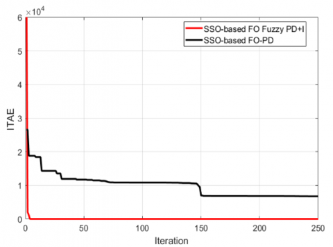
On the other hand, Table 5 summarizes the DFIG dynamic results for stator active power variation, which are defined by the rise time (RT), maximum overshoot (MO), steady-state error (SSE), settling time (ST) and ITAE, respectively. It is evident that the FO Fuzzy PD+I regulator exhibits the lowest values for RT, MO, SSE, ST, and ITAE, followed closely by PI regulator. Generally, the stator active power responses show significant improvement when utilizing the Fuzzy FOPI-TID regulator compared to the PI regulator. In addition, Figure 10 illustrates the best ITAE objective function for 250 iterations using two optimized regulators. It can be observed that the optimized FO FUZZY
PD+I regulator provides the lowest fitness function value of 0.00011. These results clearly show that the optimized FO Fuzzy PD+I regulator provides great performance in both steady state and dynamic modes.
Figure 9. DFIG stator active power
Table 5. Performance of optimized PI and FO Fuzzy PD+I regulators
|
Regulator Type |
RT (s) |
MO (%) |
SSE (%) |
ST (s) |
ITAE |
|
PI |
1.1 |
2.5 |
1.2 |
2.3 |
6767 |
|
FO Fuzzy PD+I |
0.9 |
1 |
0 |
1.22 |
0.00011 |
Figure 10. SSO optimized objective function value for 250 no. of iterations
Here's a breakdown of potential implications of the previous result in real-world applications:
5.2 Scenario 2: Effect of wind velocity fluctuation
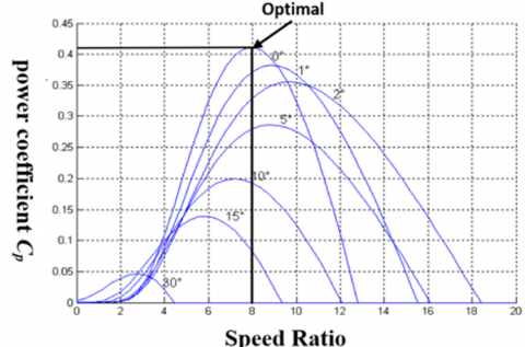
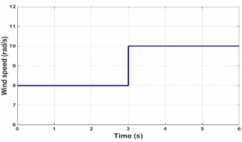
In this scenario, the DFIG parameters are assumed nominal values without external perturbation or parameter variations. The DFIG active power reference value is derived through the utilization of the MPPT technique within the WTS. The primary objective of MPPT is to effectively trace the maximum power curve spanning from the initial wind speed (8 m/s) to the rated wind speed (10 m/s). To achieve optimal power generation, the turbine's rotational speed corresponds to the optimal speed ratio $\left(\lambda_{o p t}\right)$ at which the power coefficient $\left(C_{p-\max }\right)$ reaches its maximum value. This optimal value of it is determined by tracing the curve of maximum power, as illustrated in Figure 11. Thus, to maximize the power extracted from the wind, it is imperative to maintain the tip speed ratio around its optimal value, it $\left(\lambda_{\text {opt }}=8.1, C_{p-\max }=0.415\right.$, The pitch angle $\beta=0$ (deg)).
Figure 11. The curves of $C_p(\lambda, \beta)$ for several values of the pitch angle $\beta$
Figure 12 displays a rapid increase in wind velocity from 8 m/s to 10 m/s, highlighting two distinct modes of operation (sub-synchronous and upper-synchronous). Figure 13 and 14 demonstrates the responses of rotor speed (rad/s), stator active power (W), rotor currents (A), and stator currents (A) using the optimized FO Fuzzy PD+I regulator and optimized PI regulator, respectively. According to Figures 13 and 14, the optimal values for DFIG active power are obtained at the following rotor speeds; 131 rad/s and 180 rad/s, respectively. The obtained results for the DFIG active power reveal that the actual values of the stator active power follow their references with high accuracy using the optimized FO Fuzzy PD+I regulator. In addition, the ripples’ content is successfully suppressed compared to the results obtained with the optimized PI regulator. Similarly, Figure 15 provides the THD analyses of stator current for the two control cases, the suggested control (Figure 15a), and conventional PI control (Figure 15b), respectively. From these results, we can observe that THD analyses of stator current for the optimized FO Fuzzy PD+I regulator is 0.77%, which is lower than 1.82% of the optimized PI regulator. So, the suggested FO Fuzzy PD+I regulator can offers a better current quality than traditional PI method. The THD of stator current was decreased with an amelioration ratio of about 42.30% by the optimized FO Fuzzy PD+I regulator. Let's delve into the meaning and implications in Lower THD in wind turbine applications:
Figure 12. Wind speed
Figure 13. Simulation results: the suggested regulator
5.3 Scenario 3: Effect of parameter perturbation
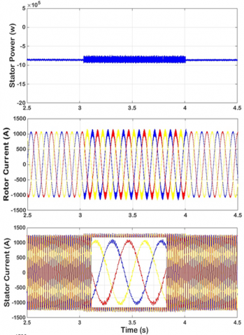
In scenario 3, we vary the parameters of the DFIG system to show the robustness of the optimized FO Fuzzy PD+I regulator and to compare its behavior with the optimized PI regulator. During the time period between3 to 4 seconds, the stator resistance of the DFIG has been increased by 150% of its nominal value, while the DFIG system operates at a constant wind velocity of 8 m/s.
Figure 14. Simulation results: the optimized PI regulator
Figure 15. THD analyses: (a) the suggested regulator, (b) the optimized PI regulator
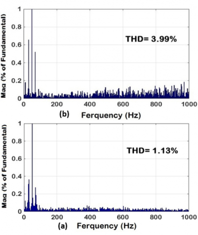
In Figures 16 and 17, we can observe that the proposed regulator has greater robustness than the optimized PI regulator as the stator power ripples have been significantly reduced with the optimized FO Fuzzy PD+I regulator. The optimized FO Fuzzy PD+I regulator effectively reduces the active power ripples by good ratios compared to the optimized PI regulator, with ratios of 99.80% and 92.15% for each regulator, respectively. Figure 18 presents the current THD using both optimized FO Fuzzy PD+I and optimized PI regulator when the DFIG parameters are changed. Based on these results, a THD of 1.13% was obtained using the optimized FO Fuzzy PD+I regulator, whereas the optimized PI regulator provided a THD of 3.99%. It is evident that the optimized FO Fuzzy PD+I regulator ensures the current THD amelioration, with an improvement percentage of 28.32 %.
The result we provided suggests that an FO Fuzzy PD+I regulator offers increased robustness compared to a traditional PI regulator in wind turbine system, under disturbances. Here's a breakdown of its potential implications in real-world wind turbine applications:
Figure 16. Simulation results: the suggested regulator
Figure 17. Simulation results: the optimized PI regulator
Figure 18. THD analyses: (a) the suggested regulator, (b) the optimized PI regulator
To enhance the dynamic response characteristics of interconnected doubly-fed induction generators (DFIGs) embedded within wind turbine systems (WTSs), this investigation introduces an innovative methodology for the design and fine-tuning of a fuzzy Proportional-Derivative with Integral (PD+I) controller. Leveraging the Social Spider Optimization (SSO) algorithm, a state-of-the-art metaheuristic optimization framework, optimal controller parameters for the proposed Fractional Order (FO) Fuzzy PD+I regulator are computed. Additionally, the robustness of the optimized FO Fuzzy PD+I controller is scrutinized under diverse sources of uncertainty, encompassing substantial variations in stator resistance, perturbations in stator active power, and fluctuations in wind velocity. Across a spectrum of examined scenarios, computational simulations consistently underscore the superiority of the optimized FO Fuzzy PD+I controller over its Proportional-Integral (PI) counterpart. Specifically, it manifests superior stator current response characteristics and adeptly attenuates power fluctuations. Moreover, the application of the optimized FO Fuzzy PD+I controller engenders a reduction in the total harmonic distortion (THD) within the stator current, thereby augmenting the overarching grid power quality. Importantly, the proposed FO Fuzzy PD+I controller evinces promise for deployment in nonlinear system settings, thus signifying a noteworthy avenue for further scholarly inquiry. Transitioning from theoretical modeling to practical implementation entails the conduct of experimental trials either in laboratory settings or upon a scaled-down DFIG-based wind turbine system. Such endeavors are indispensable for validating the practical efficacy and performance attributes of the FO Fuzzy PD+I controller. Field deployment and subsequent testing facilitate a comprehensive evaluation of the controller's performance under diverse operational conditions, thereby affording insight into any operational nuances unique to real-world deployment environments. Moreover, exploration of advanced optimization methodologies, inclusive of reinforcement learning frameworks, evolutionary algorithms, or hybrid optimization paradigms, aimed at dynamically tuning the controller's parameters in response to evolving operational exigencies, merits scholarly attention. Furthermore, leveraging the FO Fuzzy PD+I controller to undertake an exhaustive investigation into the environmental ramifications of DFIG-based wind turbine systems, encompassing comprehensive life cycle assessments, carbon footprint analyses, and endeavors geared towards fostering sustainable wind farm development, represents a laudable scholarly pursuit with potentially significant ramifications for the fiel.
[1] Burton, T., Jenkins, N., Sharpe, D., Bossanyi, E. (2011). Wind Energy Handbook. John Wiley & Sons.
[2] Chhipą, A. A., Chakrabarti, P., Bolshev, V., Chakrabarti, T., Samarin, G., Vasilyev, A. N., Ghosh, S., Kudryavtsev, A. (2022). Modeling and control strategy of wind energy conversion system with grid-connected doubly-fed induction generator. Energies, 15(18): 6694. https://doi.org/10.3390/en15186694
[3] Nian, H., Xu, Y., Chen, L., Zhu, M. (2019). Modeling and analysis of DC-link dynamics in DFIG system with an indicator function. IEEE Access, 7: 125401-125412. https://doi.org/10.1109/ACCESS.2019.2938796
[4] Gomez, L.A., Grilo, A.P., Salles, M.B.C., Sguarezi Filho, A.J. (2020). Combined control of DFIG-based wind turbine and battery energy storage system for frequency response in microgrids. Energies, 13(4): 894. https://doi.org/10.3390/en13040894
[5] Abad, G., Lopez, J., Rodriguez, M., Marroyo, L., Iwanski, G. (2011). Doubly fed induction machine: Modeling and control for wind energy generation. John Wiley & Sons.
[6] Leonhard, W. (2001). Control of Electrical Drives. Springer Science & Business Media.
[7] Pena, R., Clare, J.C., Asher, G.M. (1996). Doubly fed induction generator using back-to-back PWM converters and its application to variable-speed wind-energy generation. IEE Proceedings-Electric power applications, 143(3): 231-241. https://doi.org/10.1049/ip-epa:19960288
[8] Amrane, F., Chaiba, A., Francois, B., & Babes, B. (2017, October). Real time implementation of grid-connection control using robust PLL for WECS in variable speed DFIG-based on HCC. In 2017 5th International Conference on Electrical Engineering-Boumerdes (ICEE-B), Boumerdes, Algeria, pp. 1-5. https://doi.org/10.1109/ICEE-B.2017.8191984
[9] Amrane, F., Chaiba, A., Babas, B.E., Mekhilef, S. (2016). Design and implementation of high performance field oriented control for grid-connected doubly fed induction generator via hysteresis rotor current controller. R Revue Roumaine des Sciences Techniques, Série Électrotechnique et Énergétique 61(4): 319-324.
[10] Beltran, B., Benbouzid, M.E.H., Ahmed-Ali, T. (2012). Second-order sliding mode control of a doubly fed induction generator driven wind turbine. IEEE Transactions on Energy Conversion, 27(2): 261-269. https://doi.org/10.1109/TEC.2011.2181515
[11] Yu, X., Jiang, Z., Zhang, Y. (2008). A synergetic control approach to grid-connected, wind-turbine doubly-fed induction generators. In 2008 IEEE Power Electronics Specialists Conference, Rhodes, Greece, pp. 2070-2076. https://doi.org/10.1109/PESC.2008.4592248
[12] Amrane, F., Chaiba, A., François, B., Babes, B. (2017). Experimental design of stand-alone field oriented control for WECS in variable speed DFIG-based on hysteresis current controller. In 2017 15th International Conference on Electrical Machines, Drives and Power Systems (ELMA), Sofia, Bulgaria, pp. 304-308. https://doi.org/10.1109/ELMA.2017.7955453
[13] Mossa, M.A., Abdelhamid, M.K., Hassan, A.A., Bianchi, N. (2022). Improving the dynamic performance of a variable speed DFIG for energy conversion purposes using an effective control system. Processes, 10(3): 456. https://doi.org/10.3390/pr10030456
[14] Mahvash, H., Taher, S.A., Rahimi, M., Shahidehpour, M. (2018). DFIG performance improvement in grid connected mode by using fractional order [PI] controller. International Journal of Electrical Power & Energy Systems, 96: 398-411. https://doi.org/10.1016/j.ijepes.2017.10.008
[15] Babes, B., Boutaghane, A., Hamouda, N., Kahla, S., Kellai, A., Ellinger, T., Petzoldt, J. (2020). New optimal control of permanent magnet DC motor for photovoltaic wire feeder systems. Journal Européen des Systèmes Automatisés, 53(6): 811-823. https://doi.org/10.18280/jesa.530607
[16] Mohamed, R., Helaimi, M., Taleb, R., Gabbar, H.A., Othman, A.M. (2020). Frequency control of microgrid system based renewable generation using fractional PID controller. Indonesian Journal of Electrical Engineering and Computer Science, 19(2): 745-755. https://doi.org/10.11591/ijeecs.v19.i2.pp745-755
[17] Hamouda, N., Babes, B., Hamouda, C., Kahla, S., Ellinger, T., Petzoldt, J. (2020). Optimal tuning of fractional order proportional-integral-derivative controller for wire feeder system using ant colony optimization. Journal Européen des Systèmes Automatisés, 53(2): 157-166. https://doi.org/10.18280/jesa.530201
[18] Afghoul, H., Chikouche, D., Krim, F., Babes, B., Beddar, A. (2016). Implementation of fractional-order integral-plus-proportional controller to enhance the power quality of an electrical grid. Electric Power Components and Systems, 44(9): 1018-1028. https://doi.org/10.1080/15325008.2016.1147509
[19] Monje, C.A., Chen, Y., Vinagre, B.M., Xue, D., Feliu-Batlle, V. (2010). Fractional-order systems and controls: Fundamentals and applications. Springer Science & Business Media.
[20] Paducel, I., Safirescu, C.O., Dulf, E.H. (2022). Fractional order controller design for wind turbines. Applied Sciences, 12(17): 8400. https://doi.org/10.3390/app12178400
[21] Babes, B., Albalawi, F., Hamouda, N., Kahla, S., Ghoneim, S.S. (2021). Fractional-fuzzy PID control approach of photovoltaic-wire feeder system (PV-WFS): Simulation and HIL-based experimental investigation. IEEE Access, 9: 159933-159954. https://doi.org/10.1109/ACCESS.2021.3129608
[22] Silaa, M.Y., Barambones, O., Derbeli, M., Napole, C., Bencherif, A. (2022). Fractional order PID design for a proton exchange membrane fuel cell system using an extended grey wolf optimizer. Processes, 10(3): 450. https://doi.org/10.3390/pr10030450
[23] Mishra, A.K., Mishra, P., Mathur, H. D. (2022). Enhancing the performance of a deregulated nonlinear integrated power system utilizing a redox flow battery with a self-tuning fractional-order fuzzy controller. ISA transactions, 121: 284-305. https://doi.org/10.1016/j.isatra.2021.04.002
[24] Pan, I., Das, S. (2012). Intelligent Fractional order Systems and Control: An Introduction. Springer.
[25] Pan, I., Das, S. (2016). Fractional order fuzzy control of hybrid power system with renewable generation using chaotic PSO. ISA transactions, 62: 19-29. https://doi.org/10.1016/j.isatra.2015.03.003
[26] Mahto, T., Mukherjee, V. (2017). Fractional order fuzzy PID controller for wind energy‐based hybrid power system using quasi-oppositional harmony search algorithm. IET Generation, Transmission & Distribution, 11(13): 3299-3309. https://doi.org/10.1049/iet-gtd.2016.1975
[27] Raghavendran, C.R., Roselyn, J.P., Devaraj, D. (2020). Development and performance analysis of intelligent fault ride through control scheme in the dynamic behaviour of grid connected DFIG based wind systems. Energy Reports, 6: 2560-2576. https://doi.org/10.1016/j.egyr.2020.07.015
[28] Das, S., Pan, I., Das, S., Gupta, A. (2012). A novel fractional order fuzzy PID controller and its optimal time domain tuning based on integral performance indices. Engineering Applications of Artificial Intelligence, 25(2): 430-442. https://doi.org/10.1016/j.engappai.2011.10.004
[29] Beddar, A., Bouzekri, H., Babes, B., Afghoul, H. (2016). Experimental enhancement of fuzzy fractional order PI+ I controller of grid connected variable speed wind energy conversion system. Energy Conversion and Management, 123: 569-580. https://doi.org/10.1016/j.enconman.2016.06.070
[30] Skoczowski, S., Domek, S., Pietrusewicz, K., Broel-Plater, B. (2005). A method for improving the robustness of PID control. IEEE Transactions on Industrial Electronics, 52(6): 1669-1676. https://doi.org/10.1109/TIE.2005.858705
[31] Li, W., Chang, X.G., Wahl, F.M., Farrell, J. (2001). Tracking control of a manipulator under uncertainty by FUZZY P+ ID controller. Fuzzy Sets and Systems, 122(1): 125-137. https://doi.org/10.1016/S0165-0114(00)00019-1
[32] Er, M.J., Sun, Y.L. (2001). Hybrid fuzzy proportional-integral plus conventional derivative control of linear and nonlinear systems. IEEE Transactions on Industrial Electronics, 48(6): 1109-1117. 10.1109/41.969389
[33] Barbosa, R.S., Jesus, I.S., Silva, M.F. (2010). Fuzzy reasoning in fractional-order PD controllers. New Aspects of Applied Informatics, Biomedical Electronics & Informatics and Communications, 252-257.
[34] Ghamari, S.M., Narm, H.G., Mollaee, H. (2022). Fractional‐order fuzzy PID controller design on buck converter with antlion optimization algorithm. IET Control Theory & Applications, 16(3): 340-352. https://doi.org/10.1049/cth2.12230
[35] Arya, Y. (2019). A new cascade Fuzzy-FOPID controller for AGC performance enhancement of single and multi-area electric power systems. ISA Transactions.
[36] Paliwal, N., Srivastava, L., Pandit, M. (2022). Application of grey wolf optimization algorithm for load frequency control in multi-source single area power system. Evolutionary Intelligence, 15: 563-584. https://doi.org/10.1007/s12065-020-00530-5
[37] Hamouda, N., Babes, B., Kahla, S., Hamouda, C., Boutaghane, A. (2020). Particle swarm optimization of fuzzy fractional PDµ+ I Controllerof a PMDC motor for reliable operation of wire-feeder units ofgmaw welding machine. PRZEGLAD Elektrotechniczny, 48(12): 40-46. https://doi.org/10.15199/48.2020.12.07
[38] Hamouda, N., Babes, B., Boutaghane, A., Kahla, S., Mezaache, M. (2020). Optimal tuning of PI λ D μ controller for PMDC motor speed control using ant colony optimization algorithm for enhancing robustness of WFSs. In 2020 1st International Conference on Communications, Control Systems and Signal Processing (CCSSP), El Oued, Algeria, pp. 364-369. https://doi.org/10.1109/CCSSP49278.2020.9151609
[39] AbouOmar, M.S., Zhang, H.J., Su, Y.X. (2019). Fractional order fuzzy PID control of automotive PEM fuel cell air feed system using neural network optimization algorithm. Energies, 12(8): 1435. https://doi.org/10.3390/en12081435
[40] Pereira, L.F.D.S., Batista, E., de Brito, M.A., Godoy, R.B. (2022). A robustness analysis of a fuzzy fractional order PID controller based on genetic algorithm for a DC-DC boost converter. Electronics, 11(12): 1894. https://doi.org/10.3390/electronics11121894
[41] Osinski, C., Leandro, G.V., da Costa Oliveira, G.H. (2021). A new hybrid load frequency control strategy combining fuzzy sets and differential evolution. Journal of Control, Automation and Electrical Systems, 32(6): 1627-1638. https://doi.org/10.1007/s40313-021-00767-0
[42] Cuevas, E., Luque, A., Zaldívar, D., Pérez-Cisneros, M. (2017). Evolutionary calibration of fractional fuzzy controllers. Applied Intelligence, 47: 291-303. https://doi.org/10.1007/s10489-017-0899-y
[43] Ouadfel, S., Taleb-Ahmed, A. (2016). Social spiders optimization and flower pollination algorithm for multilevel image thresholding: A performance study. Expert Systems with Applications, 55: 566-584. https://doi.org/10.1016/j.eswa.2016.02.024
[44] Laddha, A., Hazra, A., Basu, M. (2015). Optimal operation of distributed renewable energy resources based micro-grid by using social spider optimization. In 2015 IEEE Power, Communication and Information Technology Conference (PCITC), Bhubaneswar, India, pp. 756-761. https://doi.org/10.1109/PCITC.2015.7438098
[45] Hejrati, Z., Fattahi, S., Faraji, I. (2014). Optimal congestion management using the Social Spider Optimization algorithm. In 29th International Power System Conference. https://sid.ir/paper/939214/en
[46] Vijay, R., Priya, V. (2017). Anti-islanding protection of distributed generation based on social spider optimization technique. International Journal of Advanced Engineering Research and Science, 4(6): 237193. https://doi.org/10.22161/ijaers.4.6.5
[47] Jenkal, H., Bossoufi, B., Boulezhar, A., Lilane, A., Hariss, S. (2020). Vector control of a doubly fed induction generator wind turbine. Materials Today: Proceedings, 30: 976-980. https://doi.org/10.1016/j.matpr.2020.04.360
[48] Kumar, V., Rana, K.P.S., Kumar, J., Mishra, P., Nair, S.S. (2017). A robust fractional order fuzzy P+ fuzzy I+ fuzzy D controller for nonlinear and uncertain system. International Journal of Automation and Computing, 14: 474-488. https://doi.org/10.1007/s11633-016-0981-7