Mazyed A. Al-Tak![]() | Mohd Fadzil Bin Ain*
| Mohd Fadzil Bin Ain*![]() | Omar Sh. Al-Yozbaky
| Omar Sh. Al-Yozbaky![]() | Mohamad Kamarol Mohd Jamil
| Mohamad Kamarol Mohd Jamil![]()
© 2024 The authors. This article is published by IIETA and is licensed under the CC BY 4.0 license (http://creativecommons.org/licenses/by/4.0/).
OPEN ACCESS
This study investigates transients resulting from switching a three-phase 400 kV shunt reactor. The main concern is the occurrence of current chopping during the de-energization of the shunt reactor, which can lead to overvoltages and stress on circuit breakers and the shunt reactor itself. When clearing a ground arcing fault, a neutral Earthing reactor aids in interrupting the current. Switching a grounded shunt reactor via a neutral reactor may stress circuit breakers more than switching a solidly grounded shunt reactor. This study proposes a novel circuit modification to suppress excessive transient overvoltages due to current chopping during shunt reactor de-energization. The proposed modification involves integrating an additional circuit breaker and its inherent resistance into the existing circuit. Utilizing ATP-Draw software, the study models and analyzes transient behavior specifically for a 50 MVAR reactive power rating. Different mitigation techniques, including controlled switching, surge arresters, disconnecting switches, and a novel circuit modification model, are compared based on simulation results. A new model for de-energizing shunt reactors is presented in this study, achieving significant reductions in transient voltages on both the reactor and circuit breaker compared to traditional models. This model focuses on optimized synchronization between circuit breakers, leading to an 84% voltage drop, highlighting the significant advantages of this approach.
controlled switching, neutral reactor, de-energization, current chopping, switching overvoltage, shunt reactor
Shunt reactors (SR) are applied in power systems to maintain the voltage and reactive power profiles on the transmission lines, in other words, the transmission system has a (SR) to reduce the Ferranti voltage at the transmission line's end [1, 2]. In extra high voltage (EHV) systems, shunt reactors (SRs) grounded through neutral reactors are utilized. EHV systems typically involve voltage levels exceeding 345 kV. These strategies enhance the removal of line-to-ground faults from individual poles, improving the chances of successful reclosing. These reactor setups combine both ungrounded and directly grounded reactor configurations for switching operations [3, 4]. Transformers and reactors are switched as a result of both intentional (maintenance) and unintentional (fault) reasons. Uncontrolled switching caused by any of the aforementioned problems places the equipment under thermic and dielectric stress, shortening its usable life. Switching transients not only lead to issues like thermal and dielectric degradation but can also have adverse effects on power quality. Moreover, they can disrupt the proper functioning of protective systems [5, 6]. Existing approaches for mitigating switching transients associated with shunt reactor de-energization rely on methods include pre-insertion resistors, damping reactors, RC snubbers, and surge arresters However, these often come with limitations in terms of cost, efficiency, or long-term reliability. This research proposes a novel approach that aims to address the root cause of the problem and overcome the shortcomings of conventional methods. In recent years, controlled switching is frequently used to reduce switching transients in this situation. Various charging techniques are used depending on the design and connectivity configuration [7]. Control switching operations were carried out first to prevent re-ignition/re-strike through the abrupt opening of (SRs) [8]. However, as fast controllers and sensors have improved, it is now being used to switch other power equipment as well.
In this study, the switching operations of a 400 KV shunt reactor (SR) used in transmission systems were examined. High-voltage reactors undergo frequent switching; they're turned on when the system operates with low loads and turned off when the load increases. These switching actions generate electromagnetic transients and mechanical effects. Overvoltages occur when small inductive currents are interrupted during the opening process, a phenomenon known as current chopping. Additionally, the unique challenge of reignition between the circuit-breaker contact gap can lead to extremely steep overvoltages [3].
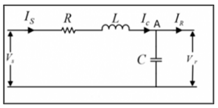
De-energizing a shunt reactor, often necessary for maintenance or load management, can unexpectedly lead to damaging overvoltages. This surge in voltage stems from the combined effects of residual energy in the reactor and it's capacitance due to a phenomenon called "current chopping." The abrupt interruption of current flow during de-energization triggers this energy release, generating high-frequency spikes that threaten the integrity of equipment connected to the circuit. [9]. Figure 1. Illustrates the diagram of charging current through the transmission line.
Figure 1. Charging current through the transmission line
This research undertakes a rigorous analysis of transient overvoltages generated during the de-energization of a 400 kV, 50 MVAr shunt reactor. The primary objective is to gain a comprehensive understanding of excessive overvoltage across the reactor and their potential to contribute to circuit breaker failures. To achieve this, A propose and evaluate a novel mitigation method capable of suppressing transient voltages during varous current chopping values.
Therefore, various techniques have been implemented such as:
1) Use of surge arrester
2) Use of controlled switching
3) Use of disconnecting switch
4) Use a proposed model represented by circuit modification
In order to accomplish these objectives, a model of (SR), system equipment was implemented in the ATP-Draw software program.
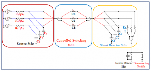
In this work, the effects of switching the shunt reactor (SR) were simulated and evaluated using the ATP-Draw program. The three-phase equivalent circuit of the power system was essential to this strategy. Figure 2 provides a detailed illustration specific to our 400 kV case study. When the shunt reactor is de-energized, the equivalent circuit simplifies to a parallel LC configuration. This configuration encompasses the reactor's inductance (L) and the inherent stray capacitance (C). Table 1 outlines the system parameters employed throughout the study [10, 11].
Figure 2. ATP-Draw equivalent model of a shunt reactor
Initially, the work subjected the circuit to uncontrolled switching to gain a comprehensive understanding of transient overvoltages. This helped analyze overvoltage levels in a shunt reactor (SR) and the recovery voltage in the circuit breaker (CB), representing a worst-case situation. The focus was on understanding how uncontrolled switching causes current chopping, a significant factor leading to these overvoltages. This investigation laid the groundwork for comprehending and tackling the primary issue behind transient overvoltages.
Table 1. Parameters of the reactor
|
Parameter |
Value |
Unit |
|
Source side parameters |
||
|
Equivalent Source Resistance (RS) |
0.77 |
Ὡ/phase |
|
Equivalent Source impedance (XL) |
6.19 |
Ὡ /phase |
|
Source side stray Capacitance (CS) |
4 |
nF/phase |
|
Shunt reactor parameters (per phase) |
||
|
Load side stray capacitance (CL) |
8.2 |
nF/phase |
|
Equivalent resistance of reactor (RL) |
8.6 |
Ὡ /phase |
|
Inductance of Reactor (L) |
9.92 |
H/phase |
|
Neutral reactor parameters (single phase) |
||
|
Neutral reactor inductance |
4.85 |
H |
|
capacitance of Neutral reactor |
0.97 |
nF |
To mitigate the harmful overvoltage values and prevent or reduce transient overvoltages, various strategies were employed. These included the use of a disconnecting switch, which changes the grounding of the SR from neutral reactor earthing to direct grounding before switching off the SR. Additionally, the effectiveness of surge arresters and controlled switching in different contexts have been explored.
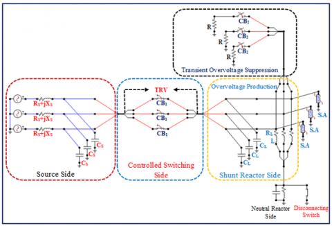
In the results section, a comparison of these mitigation techniques with the approach proposed in this study was provided. In addition to the mitigation techniques discussed earlier, the study introduces a novel strategy for mitigating transient overvoltage. The work proposes a modification to the circuit depicted in Figure 2. This modification involves adding CB2 with its associated resistance and connecting it in parallel with the terminals of the shunt reactor (SR). Figure 3 illustrates the modified circuit diagram.
Figure 3. The equivalent circuit of (SR) switching after modification
The proposed approach ensures a coordinated operation of CB1 and CB2, each possessing independent poles with different opening/closing times. The objective is to synchronize the opening time of CB1 with the closing time of CB2 for every pole. This strategic coordination enhances the capability of CB2 to absorb transient overvoltages encountered during shunt reactor (SR) de-energization. The primary objective is effective absorption of these overvoltages. This method is adept at handling different levels of current chopping during uncontrolled switching. Additionally, when coupled with controlled switching, it excels in managing transient overvoltages, thereby contributing to the overall stability of the power system. Compared to existing techniques, this method demonstrates superior capability in suppressing transient overvoltages, achieving considerably lower voltage peaks.
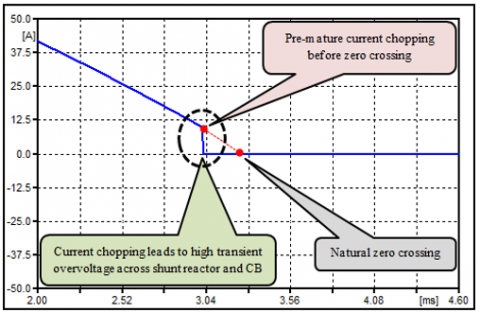
During periods of high load, shunt reactors may need to be disconnected from the power system. However, if this disconnection occurs through uncontrolled switching, the current can be interrupted before reaching its natural zero crossing, a phenomenon known as "current chopping." This abrupt interruption releases the energy stored in the shunt reactor's inductance and the parallel capacitance, resulting in the generation of a high transient voltage. The magnitude of this voltage is directly related to the severity of the current chopping event.
If these switching overvoltages reach a peak value higher than the equipment's rated switching impulse withstand voltage, it could potentially endanger the equipment. However, the presence of surge arresters that protect shunt reactors (SRs) connected to their terminals makes it unlikely for the overvoltages generated during de-energization to cause insulation failure in the shunt reactors [12]. To avoid insulation failures, it's crucial to understand the potential dielectric stress within the system before choosing equipment or technical solutions for the facilities.
The proposed model demonstrably reduces the risk of equipment damage from excessive voltage surges. This is evidenced by the results, which show an 84% decrease in transient voltage amplitudes compared to traditional de-energization methods. This significant reduction effectively protects equipment from harmful overvoltages.
Arc instability is the root cause of current chopping, characterized by a poorly damped current oscillation added to the load current [13]. It is possible for the forced current to decay from a specific value to zero in a relatively short period of time in the region of near-zero current (much earlier than the natural current zero). Current chopping is the term of this phenomenon. It happens when small inductive currents are switched off [13, 14].
Current chopping is a phenomenon that occurs when a circuit breaker (CB) is opened abruptly, causing the current to flow through the CB to become unstable and rapidly increase in magnitude. To avoid the influence of overvoltage brought on via current chopping, the shunt reactor is typically de-energized when the current is zero [3]. In the case of opening a shunt reactor using a circuit breaker (CB), the chopping number is taken into consideration. According to literatures [3, 15, 16], this concept can generally be applied to all circuit breaker types, except for vacuum circuit breakers. Vacuum circuit breakers, commonly used for shunt reactor switching in medium-voltage systems via transformer tertiary windings, exhibit current chopping behavior dependent on their contact material. This dependence renders the "chopping number" approach unsuitable for predicting chopping events in such contexts.
The total capacitance value in parallel with CB was presented using the formula in Eq. (1).
$I_{c h}=\lambda \sqrt{C_t}$ (1)
where, Ich is the level of the current that is in effect at the time of chopping; λ is the chopping number; Ct is the total capacitance parallel to the (CB) (F).
Reactor-induced overvoltage results from a phenomenon known as current chopping, where the current is interrupted before reaching zero. This interruption can lead to instability in the electrical arc. The reactor (CL) plays a significant role by storing electromagnetic energy and transferring it to the load capacitance. This energy alternates between the reactor and the load. The initial peak of this oscillation, referred to as chopping or suppression peak overvoltage (Vma), shares the same polarity as the system voltage. Surge voltages induced by de-energizing shunt reactors pose a critical risk to power systems. Capable of causing equipment damage, insulation failure, and even system instability, these spikes can lead to widespread power outages and operational disruptions. To combat this threat, researchers have developed mitigation techniques like RC snubber, surge arresters, and controlled switching, with the goal of suppressing overvoltages and enhancing system reliability. Figure 4 provides a visual representation of how the overvoltage on the load side is generated when there is an instantaneous interruption of current. Polarity, or recovery voltage peak, is the 2nd peak in the oscillation. The frequency of the load's oscillation, compared to the system voltage, ranges between 1 and 5 KHZ. The value will gradually decline until it reaches zero in the case that the (CB) completely interrupts. It is possible to determine the suppression peak overvoltage (Vma) or chopping overvoltage values from energy balance as described in Eq. (2) [9].
Figure 4. Current chopping and (SR) overvoltage [9]
$\begin{gathered} & \text{Energy at current Interruption = Energy at chopping Peak Voltage} \\ & \frac{1}{2} C V^2=\frac{1}{2} L I_{c h}^2+\frac{1}{2} C V_O^2\end{gathered}$ (2)
where, C is capacitance on the load side; Ich is current chopping level; V is maximum chopping voltage, Vo is peak voltage through the inductor when the current is disconnected, the equation is revised. The suppression peak overvoltage's magnitude is given by Eq. (3).
$\frac{V}{V_O}=\sqrt{1+\frac{L I_{c h}^2}{C V_O^2}}$ (3)
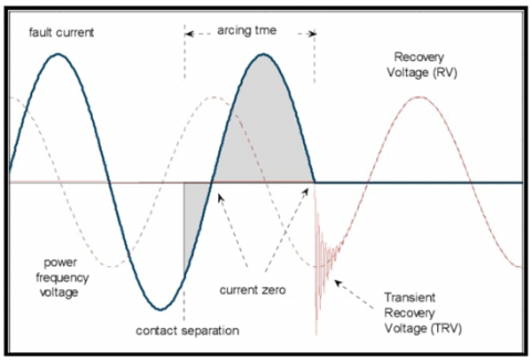
Grounding (SR) through neutral reactors helps prevent secondary arcs. The size of the neutral reactor is selected according to system requirements, and manufacturers offer custom options based on size specifications. The equation for grounded neutral reactors mainly affects the first pole-to-clear. In such cases, there's minimal or no neutral shift. When considering the second and third pole-to-clear, the release of inductive energy during current chopping decreases. This means that chopping overvoltage is generally lower for the second and third poles unless the chopping current level is significantly higher than that of the first pole [3]. In practical field experiments conducted on 400 kV switchyards with similar reactors and circuit breakers, chopping current values typically ranged from 2 to 14 A [4, 17]. Following a current interruption, a (TRV) would be generated across the CB contacts. If damping is ignored, its maximum predicted value is equal to the sum of the source's peak voltages and the overvoltage caused by current chopping. TRV, calculated using analytical or simulation methods, represents the voltage surge after current interruption. Higher TRV stresses circuit breaker insulation and current interruption capability. Optimizing these aspects based on accurate TRV calculations ensures reliable circuit breaker performance and system protection. Figure 5. explain principles of current interruption and associated effect.
Figure 5. Principles of current interruption and its effect [9]
According to recommendations made by researchers [3, 18], the maximum switching overvoltage values between (CB) contacts produced by current chopping needs to be ≤80% of the switching impulse to withstand voltage at its highest point, i.e., 3.63 p.u.
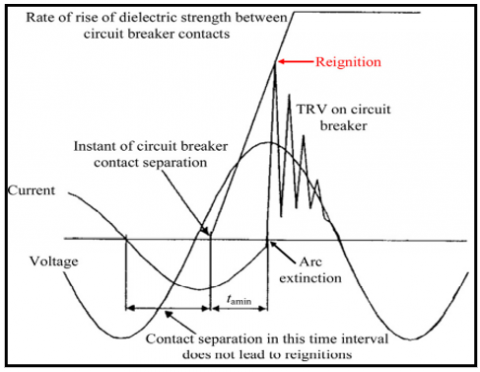
Re-ignition is the reappearance of current through an arc that has been extinguished. This can happen during the de-energization of a shunt reactor when the circuit breaker is opened to disconnect the reactor from the power system [2, 19]. The circuit breaker (CB) is essential for disconnecting current and ensuring it drops to zero. The gap distance between circuit breaker contacts plays a crucial role in arc extinction and, consequently, in the occurrence of re-ignition. A larger gap generally facilitates more effective current interruption by providing ample space for energy dissipation within the arc channel. This effectively reduces the chances of the arc reigniting after its initial extinction. Conversely, a smaller gap can increase the risk of re-ignition, particularly under high Transient Recovery Voltage (TRV) conditions, Figure 6. Shows TRV due to current interruption. TRV, closely linked to arc extinction dynamics, represents the voltage appearing across the breaker contacts after current interruption. If this voltage exceeds the dielectric strength of the gap medium (air or vacuum), it can trigger re-initiation of the arc [5]. Re-ignition occurs when the arcing time is short and contact gaps cannot withstand voltage stress. When inductive current is interrupted, re-ignition occurs, causing stress on the circuit breaker (CB). Load voltage is conveyed back to the power source as a high-frequency oscillation, causing overvoltage [16]. Optimizing circuit breaker design involves considerations of factors like arcing time and Transient Recovery Voltage (TRV) to minimize the risk of re-ignition. Advanced techniques and materials can reduce arcing time, the duration between contact separation and arc extinction. By controlling TRV and minimizing arcing time through design optimization, the probability of re-ignition is diminished, enhancing interruption performance and system reliability [20]. Advances in circuit breaker technologies, including SF6, vacuum, and others, further contribute to minimizing re-ignition, thereby improving overall performance in medium voltage applications.
Figure 6. Target for contact separation in order to eliminate resignations [18]
This section will conduct a comprehensive examination of each mitigation strategy and provide a detailed explanation of the results. This will then conduct a comparative study and discussion of the results of each strategy. This study comprehensively evaluated the proposed model against established mitigation strategies, including surge arresters, controlled switching, and disconnecting switches. The comprehensive results demonstrated the proposed model's ability to achieve greater voltage reductions, consistently surpassing the voltage reduction capabilities of traditional methods. Findings emphasized the significance of accurate circuit breaker synchronization in maximizing the proposed model's effectiveness. Precise synchronization minimized the occurrence of harmful transient voltages compared to uncontrolled switching scenarios.
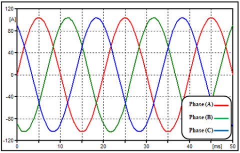
In this section of the article, the findings of uncontrolled switching and its detrimental effects on system equipment will be further discussed. It's important to note that no mitigation methods were employed in this part of the study. This choice was deliberate, as it allowed us to highlight the unfavorable conditions that can detrimentally affect equipment operation. Figure 7 shows the current values during a steady-state condition. It is particularly notable when low inductive currents are interrupted, causing an abrupt cessation of current flow prior to reaching its natural zero crossing point.
Figure 7. Current through (SR) at steady state
Figure 8. (CB) currents during the (SR) de-energization
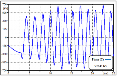
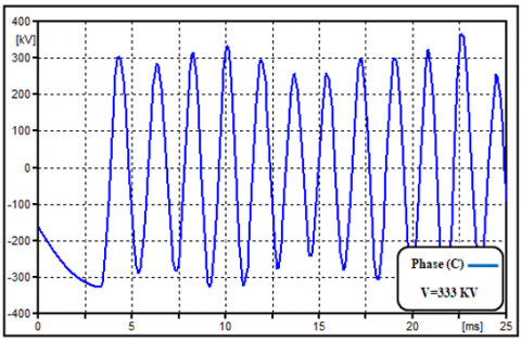
Figure 9. Chopping overvoltage across (SR) in phase C
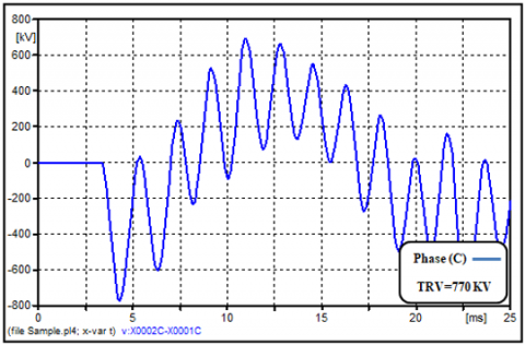
Figure 10. High TRV across the (CB) in phase C
The release of energy from the reactor's inductance causes electromagnetic transients, leading to switching overvoltages. Uncontrolled switching in power systems can cause dangerous voltage surge– transient overvoltages across shunt reactor and TRVs across circuit breaker – due to abrupt current chopping, as shown in Figure 8. These surges can damage equipment and even cause breaker failure. Shunt reactors are especially vulnerable, as their windings can face excessive voltages during de-energization. It is importance of implementing adequate mitigation strategies like using of surge arrester and employing controlled switching techniques wherever possible. These phenomena are further depicted in Figures 9 and 10.
8.1 Surge arresters
A 3-phase surge arrester is connected near the shunt reactor (SR), and it effectively reduces the amplitude of the system recovery voltage. It can be seen this reduction in overvoltage at the SR stations in Figures 11 and 12, along with the recovery voltage across the circuit breaker (CB) contacts.
Figure 11. Overvoltage in (SR) terminal when using surge arrester
Surge arresters can effectively reduce transient overvoltage during shunt reactor de-energization, but they may not be perfect. While surge arresters are a widely employed mitigation strategy for overvoltages, their capabilities have limitations. Optimized for specific voltage thresholds, they effectively manage smaller transient spikes. However, under severe current chopping conditions, the resulting overvoltages can far exceed the arresters' rated capacity, leading to overstress and potential malfunction.
Figure 12. TRV across CB when using surge arrester
8.2 Phase controlled
Figure 13. Current through (SR) when using controlled switching
Figure 14. Overvoltage across (SR) terminal when using controlled switching
In this study, the researchers have examined the controlled switching process. This approach is used with CBs, as shown in Figure 13, to guarantee a minimal arcing duration and a proper disconnection at the 1st current zero following contact separating. Controlled switching is a promising strategy for mitigating transient overvoltages during shunt reactor de-energization. Its precision and flexibility enable a well-calibrated approach to managing voltage transients, potentially reducing their impact on the power system. Results show that controlled switching can significantly diminish transient overvoltage magnitudes, offering effective mitigation. This approach is valuable for engineers, contributing to enhanced voltage stability and improved operational reliability during shunt reactor de-energization scenarios. Figure 14 shows the voltage value across the reactor terminals.
Figure 15. TRV across CB when using controlled switching
Although the transient overvoltage across the CB and (SR) is reduced by controlled switching, the recovery voltage remains high. Therefore, in order to avoid undesirable conditions affecting system operation that could be caused by changes in system parameters such as stray reactor capacitance, circuit modifications are required to avoid the creation of a large TRV across the CB. Figure 15 shows the TRV value across the CB contacts.
8.3 Using of disconnecting switch
Connecting the shunt reactor's neutral point to the ground just before switching off the (SR) is another approach to reduce switching overvoltage. A single pole disconnect switch (described in Figure 2) can be used for this purpose. Through this disconnected switch, the “(SR) that is grounded through a neutral reactor scheme” converts to “directly earthed (SR) scheme”. An additional switching mechanism known as a control switch is applied. The results were improved by applying the controlled switching technique and the disconnecting switch across the neutral reactor at the same time.
Figure 16. Overvoltage across (SR) terminal with directly grounded
Figure 17. TRV across CB with directly grounded
Figures 16 and 17 show the overvoltage through SR and TRV across CB while using directly grounded instead of grounding through neutral reactor. The results demonstrate that there is enough room to alter withstand levels between the voltages at the (SR) station and the recovery voltage at the CB terminals. This strategy is more productive compared to earlier techniques for reducing switching overvoltage's since these voltages are substantially lower than in earlier circumstances.
8.4 Using circuit modification
The model proposed in this section proves highly effective in minimizing overvoltages across the shunt reactor (SR) and transient recovery voltage (TRV) across the circuit breaker (CB), especially when compared to conventional methods. The results have been divided into two sections for more straightforward understanding. Part 1 displays the outcomes when using the circuit modification technique with uncontrolled switching, while Part 2 presents results from combining the circuit modification technique with controlled switching. This division helps underscore the significance of using circuit modification as a recommended approach. Figures 18 and 19 show the overvoltages across the CB and SR when using the circuit modification.
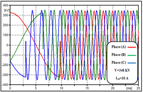
Figure 18. Overvoltage across (SR) terminal using circuit modification when Ich=10 A
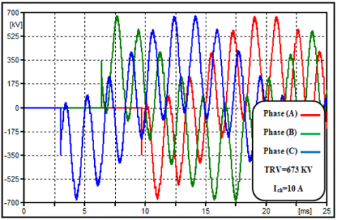
When employing the modified circuit with uncontrolled switching, Figures 18 and 19 respectively exhibit the overvoltages across the CB and shunt reactor. The proposed methodology of circuit modification decreased the transient overvoltage even with significant current chopping. The modified circuit served as an overvoltage absorber.
Figure 19. TRV across CB using circuit modification when Ich=10 A
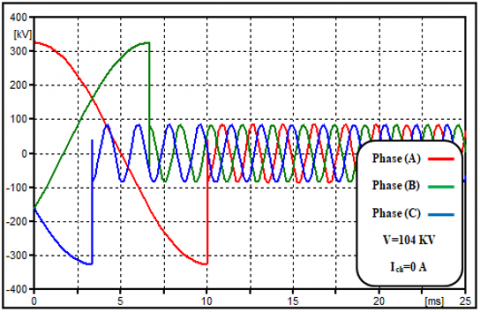
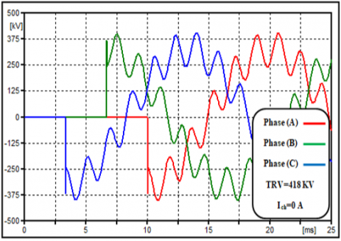
TRV over the circuit breaker (CB) and overvoltage across the shunt reactor (SR) were analyzed with circuit modification when Ich=0 A. When the modified circuit was combined with controlled switching, the transient voltage across the SR and CB was recorded in Figures 20 and 21.
Figure 20. Overvoltage across (SR) terminal using circuit modification when Ich=0 A
Figure 21. TRV across CB using circuit modification when Ich=0 A
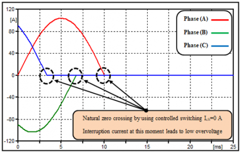
Notably, the de-energization of the shunt reactor did not produce any transient overvoltages when controlled switching was employed alongside circuit modification. This approach effectively absorbed a significant portion of transient overvoltages for both the SR and CB.
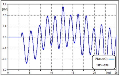
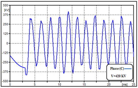
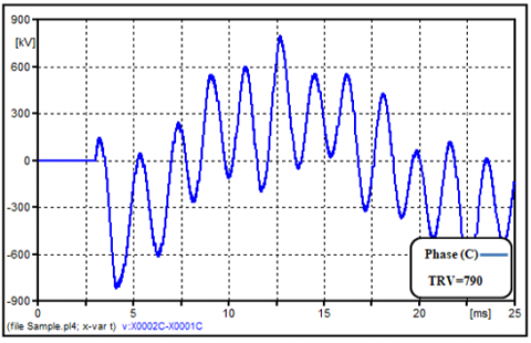
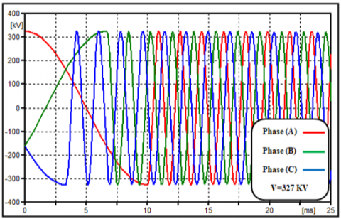
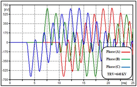
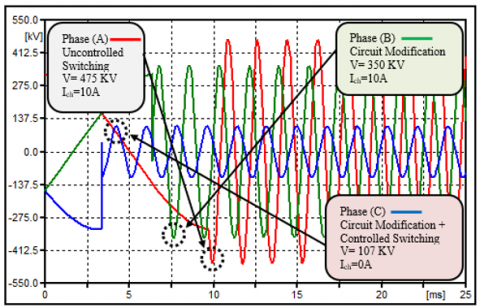
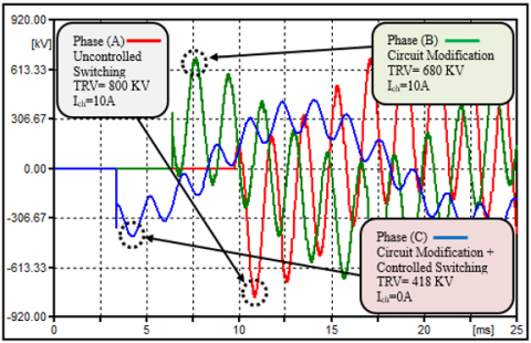
To facilitate a clear comparison of data and demonstrate the impact of circuit modification as a proposed method, it has categorized the phases as follows: Phase (A) represents uncontrolled switching, meaning no overvoltage suppression method was used. Phase (B) signifies uncontrolled switching but with the application of circuit modification for overvoltage suppression. Phase (C) represents the ideal scenario for overvoltage suppression, which includes both circuit modification and controlled switching. Figures 22 and 23 offer a visual comparison of phases (A), (B), and (C). Table 2 illustrates a comparison of overvoltage across shunt reactor and TRV across circuit breaker under various suppression transient overvoltage scenarios.
Figure 22. Clarification of overvoltage across (SR) between using circuit modification with Ich=10 A and with Ich=0 A
Figure 23. Clarification of TRV across CB between using circuit modification with Ich=10 A and with Ich=0 A
Table 2. An overview of the study and the comparison the findings noted here
|
Scenario |
|||||||
|
|
|
1 |
2 |
3 |
4 |
5 |
6 |
|
Methods used |
Controlled Switching |
X |
X |
√ |
√ |
X |
√ |
|
Surge Arrester |
X |
√ |
√ |
√ |
X |
X |
|
|
Disconnecting Switch |
X |
X |
X |
√ |
√ |
√ |
|
|
Circuit Modification |
X |
X |
X |
X |
√ |
√ |
|
|
Overvoltage's |
A |
370 |
328 |
260 |
326 |
345 |
104 |
|
B |
502 |
431 |
360 |
327 |
350 |
106 |
|
|
C |
543 |
420 |
333 |
328 |
348 |
107 |
|
|
TRV |
A |
700 |
633 |
600 |
641 |
672 |
422 |
|
B |
841 |
759 |
721 |
639 |
675 |
420 |
|
|
C |
930 |
790 |
770 |
640 |
673 |
418 |
|
In this study, we explored switching transients caused by uncontrolled and controlled switching of a 3-phase 400 KV shunt reactor (SR) with a reactive power of 50 Mvar. Transient overvoltages can lead to serious consequences, including equipment damage, insulation breakdown, and potential re-ignition phenomena.Various scenarios were examined, including uncontrolled switching, surge arrester use, controlled switching, disconnecting switches, and a novel circuit modification-based approach.
The simulations revealed that controlled switching can alter the system's recovery voltage peak, delaying it to prevent re-ignition. However, it doesn't fully protect against excessive recovery overvoltage. Surge arresters effectively controlled both transient recovery voltage (TRV) in the circuit breaker (CB) and overvoltages in the shunt reactor (SR). Notably, the proposed approach effectively managed high current chopping levels, successfully keeping overvoltages below the 80% threshold stipulated by IEEE standards. This achievement is significant, as exceeding this threshold can lead to equipment damage, insulation breakdown, and ultimately, system instability.
The proposed method enables precise control over re-ignition overvoltage duration and magnitude. Precise circuit breaker synchronization is crucial for the proposed model's optimal performance, effectively mitigating voltage surges and enhancing power system stability. Beyond reducing transient overvoltage by 84%, it offers additional benefits, including insulation preservation, lower re-ignition risk, extended equipment lifespan, reduced maintenance costs, and prevention of CB contact wear.
This work was supported by Universiti Sains Malaysia, under Research University Grant Scheme (RUI) 1001/PELECT/8014127.
[1] Moore, T., Schmid, F., Tricoli, P. (2022). Voltage transient management for alternating current trains with vacuum circuit breakers. IET Electrical Systems in Transportation, 12(1): 1-14. https://doi.org/10.1049/els2.12034
[2] Samimi, M. H., Ahmadi-Joneidi, I., Majzoobi, A., Golshannavaz, S. (2018). Appropriate selection of shunt compensation reactor in parallel transmission lines: A case study. International Journal of Electrical Power & Energy Systems, 96: 163-173. https://doi.org/10.1016/j.ijepes.2017.09.041
[3] IEEE Power and Energy Society (2009). IEEE Guide for the Application of Shunt Reactor Switching. IEEE Std C37.015 (Revision of IEEE Std C37.015-1993).
[4] Aleksandrova, M.I., Naumov, V.A., Antonov, V.I., Ivanov, N.G. (2020). Optimal conditions for controlled switching of a three-phase shunt reactor. Power Technology and Engineering, 54: 438-443. https://doi.org/10.1007/s10749-020-01229-4
[5] Geng, Y., Dong, J., Chen, X., et al. (2021). Three-phase modeling of 40.5-kV vacuum circuit breaker switching off shunt reactors and overvoltage suppression measure analysis. Electric Power Systems Research, 194: 107058. https://doi.org/10.1016/j.epsr.2021.107058
[6] Lin, X., Lu, J., Tian, Q., Weng, H., Li, Z., Tong, C., Li, M., Sun, J., Yang, D. (2015). Abnormal operation behavior analysis and countermeasures on the differential protection of converter transformer. International Journal of Electrical Power & Energy Systems, 64: 516-525. https://doi.org/10.1016/j.ijepes.2014.07.048
[7] Bojić, S., Babić, B., Uglešić, I. (2018). Comparative research into transients by switching of high voltage shunt reactor. Electric Power Systems Research, 162: 74-82. https://doi.org/10.1016/j.epsr.2018.04.018
[8] Al-Tak, M.A., Ain, M.F.B., Al-Yozbaky, O.S., Jamil, M.K.M. (2022). Impact of shunt reactor overvoltages switching in high voltage system. In 2022 International Conference on Engineering and Emerging Technologies (ICEET), Kuala Lumpur, Malaysia, pp. 1-6. https://doi.org/10.1109/ICEET56468.2022.10007338
[9] Limtrakul, K., Premrudeepreechacharn, S., Baghzouz, Y. (2018). Analysis of replacement from disconnecting switch to circuit breaker for 500 kV line shunt reactor. In 2018 18th International Conference on Harmonics and Quality of Power (ICHQP), Ljubljana, Slovenia, pp. 1-6. https://doi.org/10.1109/ICHQP.2018.8378944
[10] Sonagra, M., Parikh, U., Upadhyay, V. (2019). Controlled switching of non-coupled & coupled reactor for re-ignition free de-energization operation. In 2019 IEEE 5th International Conference for Convergence in Technology (I2CT), Bombay, India, pp. 1-6. https://doi.org/10.1109/I2CT45611.2019.9033675
[11] Barghandan, A., Sedaghat, B. (2015). Simulation of switching overvoltages of 400 kV shunt reactor. Transformers Magazine, 2(1): 50-59.
[12] Filipović-Grčić, B., Franc, B., Uglešić, I., Pavić, I., Keitoue, S., Murat, I., Ivanković, I. (2017). Monitoring of transient overvoltages on the power transformers and shunt reactors–field experience in the Croatian power transmission system. Procedia Engineering, 202: 29-42. https://doi.org/10.1016/j.proeng.2017.09.692
[13] Shpiganovich, A.N., Shpiganovich, A.A., Pushnitsa, K.A. (2017). On the applicability of the Mayr arc model for studying current chopping and overvoltages generated by low-oil current breakers. Russian Electrical Engineering, 88: 378-380. https://doi.org/10.3103/S1068371217060141
[14] Xin, Y.L., Yang, Y.H., Zhao, B.N., Xu, L., Yu, Z.Y., Tang, W.H. (2022). Configuration of suppression schemes against high-frequency transient reignition overvoltages caused by shunt reactor switching-off in offshore wind farms. International Journal of Electrical Power & Energy Systems, 141: 108170. https://doi.org/10.1016/j.ijepes.2022.108170
[15] IEEE Power Engineering Society. (2008). IEEE Standard Requirements, Terminology, and Test Code for Shunt Reactors Rated Over 500 kVA. IEEE Std C57.21TM-2008 (Revision IEEE Std C57.21-1990).
[16] IEEE Power and Energy Society. (2018). IEEE Guide for the Application of Shunt Reactor Switching. IEEE Std C37.015TM-2017 (Revision of IEEE Std C37.015-2009).
[17] Xemard, A., Jurisic, B., Rioual, M., Olivier, A., Sellin, E. (2020). Interruption of small, medium-voltage transformer current with a vacuum circuit breaker. Electric Power Systems Research, 187: 106502. https://doi.org/10.1016/j.epsr.2020.106502
[18] IEC1233 (1944). Historical revision information - high-voltage alternating current circuit-breaker- inductive load switching. https://www.document-center.com/standards/show/IEC-1233/ history/ 1ST% 20 EDITION
[19] Chrysochos, A.I., Papadopoulos, T.A., Papagiannis, G.K. (2015). Rigorous calculation method for resonance frequencies in transmission line responses. IET Generation, Transmission & Distribution, 9(8): 767-778. https://doi.org/10.1049/iet-gtd.2014.0948
[20] Župan, A., Filipović-Grčić, B., Filipović-Grčić, D. (2016). Transients caused by switching of 420 kV three-phase variable shunt reactor. Electric Power Systems Research, 138: 50-57. https://doi.org/10.1016/j.epsr.2015.12.010