Xuan Ngoc Nguyen![]() | Van Nhu Tran*
| Van Nhu Tran*![]() | Van Tan Vu
| Van Tan Vu![]() | Tien Phuc Dang
| Tien Phuc Dang![]()
© 2024 The authors. This article is published by IIETA and is licensed under the CC BY 4.0 license (http://creativecommons.org/licenses/by/4.0/).
OPEN ACCESS
The enhancement of rollover stability in vehicles, particularly in liquid tank trucks, is imperative for reducing the risk of vehicular rollovers and consequent threats to human life and property. The dynamic behavior of the liquid within the tank during maneuvers such as turning or lane-changing plays a significant role in the vehicle's stability. It has been demonstrated that the implementation of a Proportional Integral Derivative (PID) controller within the stabilizer bar of an active suspension system can substantially mitigate the vehicle's propensity to roll. This mitigation is quantitatively evidenced by reductions in the lateral load transfer ratio (LTR) and the roll angle (TRA) of the suspension system. Specifically, during steady turning maneuvers, a decrease of 5.6% in LTR and 12.9% in TRA was observed for liquid levels deemed most hazardous at heights of 1.2m and 1.6m, respectively. Similarly, during lane-changing maneuvers, LTR was reduced by 6.2%, and TRA was decreased by 9.1% at critical liquid levels of 0.8m and 1.6m. These analytical outcomes were derived through the application of the Lagrange method and the quasi-static method for establishing the fluid vibration equation within the tank, supplemented by D'Alembert's principle in constructing a four Degrees of Freedom (DOFs) roll model for the differential equation system of vehicle motion. This research underpins the foundational principles for the design, manufacture, and enhancement of suspension systems, and elucidates the direction for future investigations into tank trucks transporting various liquid types.
rollover stability, tank truck, PID controller, lateral load transfer ratio, the circle tank, quasi-static
Rollover accidents are the most serious because they not only endanger everyone and everything in the car but also affect the vehicles or people around that range. According to statistics from NHTSA [1], the number of vehicle rollover accidents in 2022 decreased by 6% compared to 2021 due to the epidemic, but the number of accidents in 2022 occurred in a very large number of 7,133 cases. Therefore, it is necessary to take measures or improve the vehicle's system engineering to reduce the tendency to roll over. Typically, in the research [2], the height of the roll center of the McPherson suspension was reduced in order to reduce the influence on the vehicle's dynamic characteristics by the ADAMS/Car software. The analysis results showed that the height of the roll center decreased but the lateral load transfer value increased, so it was necessary to change the contribution of the sprung mass to reduce this value. Similar to the above study, Sree Ram et al. [3] has also proposed many different suspension structures for three-wheelers using the matrix selection method and then applied the Adams/Car 3D model to analyze and optimize the parameters of the rollover ratio, the movement ratio, and the tilt angle of the shock absorbers in order to increase the rolling stability of the vehicle. In addition, there are some current studies using active control to reduce the possibility of rolling over, such as in the study [4] that used a fuzzy controller (FLC) and a linear quadratic regulator (LQR) to create the optimal torque for the three-degree-of-freedom vehicle model. This torque increases the rollover stability and amplitude of the vehicle in the case of fishhook movement and single-lane change. Quguang et al. [5] set up a two-degree-of-freedom heavy truck model to analyze the roll stability dynamics using Matlab Simulink, thereby applying a PID feedback controller to control the anti-roll torque to improve the vehicle's stability through reducing the angle of yaw and roll and the value of the lateral load transfer ratio (LTR, the vertical reaction force distribution coefficient at two wheels of an axle) in the case of a vehicle moving in a sinusoidal profile. For the study [6], using the theory of the internal control model (IMC) to set up the front wheel angle monitoring controller, the analysis is based on the three-degree-of-freedom tractor roll-over stability dynamic model. The analysis results show that the proposed model of active anti-roll control can control the steering angle in a stable range by keeping the LTR value stable.
In the majority of commercial truck operations, the load on the vehicle is fixed and concentrated. But under certain circumstances, loads can move within the vehicle, potentially affecting turn and overturn performance. The most common examples of moving loads are liquid tankers, which can be either full or partially loaded; refrigerated trucks carrying hanging carcasses; and livestock. The performance characteristics of commercial vehicles used in these cases may be affected by the free movement of the load in a vertical or horizontal direction. The most important is the tank truck without a liquid bulkhead. As the vehicle rotates, the liquid inside the tank also moves uncontrollably because the tank is partially or fully filled. This fluid movement can occur out of phase with the vehicle's lateral motion; somehow, it becomes resonant and leads to a decrease in the threshold of tipping stability [7]. Nguyen et al. [8] analyzed the rollover stability of a circular liquid tanker truck in the case of a single-lane change. The article uses the LTR value to evaluate the vehicle's roll stability based on the rollover stability dynamics model to determine that at the liquid level height of 0.4 and 0.8 m and the movement at a speed of 100 km/h, the vehicle will roll over. In the study [9], analysis of lateral stability analysis of elliptical liquid tanker trucks based on the analysis of motion of a part of liquid inside the tanks, the authors used a quasi-static model to simulate the movement of liquid inside the tank in the form of a simple pendulum combined with the Lagrange method and Newton's law to analyze the dynamical model of the vehicle, and the results showed that the liquid level accounted for 40% and 60% of the volume of the tank, and the vehicle tends to roll. Therefore, in the world, there have been a number of studies to limit the rollover of specialized vehicles carrying liquids. Kineto-static dynamic analysis of tank trucks is used in the paper [10] for different types of liquid tanks (circle, elliptical, and oval) that hold some liquid. The goal is to find the rollover threshold for each type by balancing the total rebound and roll moments, which leads to the best structural results for the liquid tank. Besides, it is possible to reduce the tipping moment due to the influence of various factors such as horizontal acceleration and load in the tank by using genetic algorithms to change the shape of the elliptical tank model. The algorithm analyzes the horizontal and vertical displacement of the center of gravity of the liquid at different volume levels and simulates determining the proposed tank shape with a higher rollover moment than the original circle and elliptical tank [11]. Similarly, Yu and Chu [12] have proposed a dynamic model with respect to the center of gravity of the liquid in the elliptical tank at different levels to solve the problem of rollover stability that may occur during vehicle control. Applying the Lagrange method to the equivalent mechanical model of a liquid tank and the vehicle motion model of the elliptical tank truck, then optimized by the genetic algorithm method, four optimal geometries have been calculated to investigate the rollover stability of the vehicle, and the simulation results show that the elliptical cross-sectional tank, with a = 1.6–1.7 m (long axis) and b = 1.15–1.25 m (short axis), achieves the best stability.
Based on the above-mentioned research contents, it is shown that most commercial vehicles use a controller, while specialized vehicles for transporting liquids change the shape and size of the tank to optimize stability. Therefore, in this study, a method to increase the rollover stability of the liquid circular tank trucks will be proposed by determining the parameters of the PID controller for the active suspension system. The analysis evaluates the effectiveness of this controller through a multi-point vehicle dynamics model and a quasi-static method for fluid movement in the tank.
2.1 Simulation model
The vehicle is actually a complex mechanical system with many details and mass-bearing parts linked together, affecting indirectly as well as directly the movement of the vehicle on the road. In addition, for liquid tank trucks, when the vehicle changes direction, the liquid in the tank fluctuates, which affects the tilt of the vehicle body, or conversely, when the vehicle body is tilted, the amplitude of liquid fluctuation will be higher, causing the vehicle to tilt more and tend to roll horizontally. So the study of the rollover stability of the liquid tank truck is too complicated. The dynamic model of the vehicle in the study is divided into two parts to build the system of differential equations of motion, which are the fluid motion model in the tank and the vehicle dynamics model.
The fluid motion model uses the cross-sectional model of a circular tank with a quasi-static method. When the vehicle is moving in the tank containing a part of the liquid, the liquid surface is not rippled or stable, and the center of gravity of the liquid part will move in the circular tank, as in the study [13]. This is combined with a simulation of the motion of the trammel pendulum [14] to analyze the dynamics of the liquid.
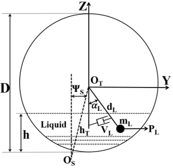
Figure 1. The dynamic model of liquid in tank truck
Figure 1 depicts the fluid moving inside the tank with the center of the tank coincident with the center of the ZOTY coordinate system, angle αL is the oscillation angle of the liquid mass relative to the vertical. Apply the Lagrange method to the fluid motion model in the tank in Figure 1 to build a differential equation to simulate the liquid's oscillation as follows:
$\begin{aligned} & m_L d_L h_T \ddot{\psi}_S+m_L d_L^2 \ddot{\alpha}_L+m_L d_L h_T \alpha_L \dot{\alpha}_L \dot{\psi}_S \\ & +m_L d_L^2 \alpha_L \dot{\alpha}_L^2+m_L g d_L \sin \alpha_L+V_L \dot{\alpha}_L=P_L d_L\end{aligned}$ (1)
The mass of liquid mL depends on the size of the tank and the height h of the liquid level in the tank defined by Eq. (2):
$\begin{aligned} & 1000 d_L\left(\frac{\left[2 \arccos \left(\frac{D-2 h}{D}\right)\right] D^2}{8}\right) -\left(\frac{D}{2}-d_L\right)^2\left[\tan \left(\arccos \left(\frac{D-2 h}{D}\right)\right)\right]=m_L\end{aligned}$ (2)
The distance dL from center OT of tank to center of mL is also determined by Eq. (3):
$\frac{D}{2}-\frac{\frac{{{D}^{3}}arccos(\frac{D-2h}{D})}{8}-\frac{{{D}^{3}}}{12}sin(arccos(\frac{D-2h}{D}))}{\frac{{{D}^{2}}.arccos(\frac{D-2h}{D})}{4}-{{(\frac{D-2h}{D})}^{2}}tan(arccos(\frac{D-2h}{D})}-\frac{{{(\frac{D-2h}{D})}^{2}}tan(arccos(\frac{D-2h}{D})).(\frac{2h}{3}+\frac{D}{6})}{\frac{{{D}^{2}}.arccos(\frac{D-2h}{D})}{4}-{{(\frac{D-2h}{D})}^{2}}tan(arccos(\frac{D-2h}{D})}={{d}_{L}}$ (3)
When the vehicle changes the direction of motion, it will generate centrifugal force [15] acting on the liquid mass inside the tank causing the liquid mass to vibrate, this force is presented by Eq. (4):
$P_L=m_L a_D$ (4)
The value of the lateral acceleration aD depends on the change in the direction of the vehicle's movement. The case of the vehicle turns around with a constant radius R and speed v [16, 17] is presented in Eq. (5) as follows:
$a_D=\frac{v^2}{R}$ (5)
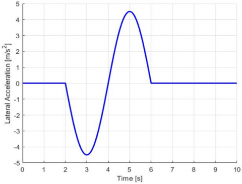
The case of the vehicle changes lanes [18, 19] is simulated as shown in Figure 2.
Figure 2. Lateral acceleration input as lane change maneuver
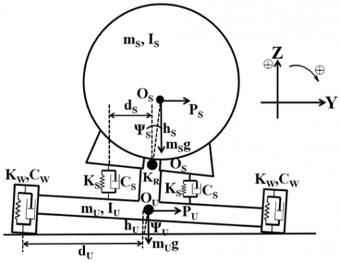
Besides, the dynamic model of the vehicle is built on the basis of the roll model [20] and the independent oscillation model on an axis in the horizontal plane passing through the wheel center, unaffected by the excitation of the road surface. Sprung mass mS is the mass part placed on the suspension system, including the tank without liquid and the chassis. These details are considered to be absolutely rigid, referring to the center of gravity, and symmetrical about the vehicle's axis; this part has two degrees of freedom (DOF): displacement ZS along the longitudinal axis and inclination angle ΨS of the vehicle body. The suspension system of the truck includes an elastic part, a shock absorber, and a stabilizer bar to help the vehicle move stably. The unsprung mass mU is the fraction of the rear and front axle masses relative to the vertical plane containing the center of gravity of the rear axle, perpendicular to the longitudinal axis of the vehicle, which is placed under the suspension with vertical displacement ZU and angle ΨU; wheel mass is assumed to be concentrated in the axle and ignores the effect of lateral deformation of the tire. This model is represented in Figure 3.
Figure 3. The dynamic model of vehicle without the fluid
When the vehicle turns or changes lanes, a reaction force from the vertical road surface will appear on both sides of the wheel, acting on the left wheel F1 and the right wheel F2, which is determined by the following formula:
$\left\{\begin{array}{l}F_1=0.5 g\left(m_S+m_L+m_U\right) \\ -K_W\left(Z_U+\psi_U d_U\right)-C_W\left(\dot{Z}_U+\dot{\psi}_U d_U\right) \\ F_2=0.5 g\left(m_S+m_L+m_U\right) \\ -K_W\left(Z_U-\psi_U d_U\right)-C_W\left(\dot{Z}_U-\dot{\psi}_U d_U\right)\end{array}\right.$ (6)
When the vehicle is roll to the right, the force F1 will be zero, applying D'Alembert's Principle to the roll model of vehicle with the positive direction is opposite to the acceleration due to gravity and the same direction of rotation is clockwise. Analyze the movement of the suspended mass and the unsuspended mass after the influence of inertia force during a turning or lane change to will be rolled. The rollover differential equation of the vehicle corresponding to the 4 DOF of the model is shown as follow:
The rollover differential equation system of the sprung mass:
$\left\{\begin{array}{l}\left(m_S+m_L\right) \ddot{Z}_S+2 K_S\left(Z_S-Z_U\right) \\ +2 C_S\left(\dot{Z}_S-\dot{Z}_U\right)+m_L \dot{\alpha}_L^2 d_L \cos \alpha_L+m_L \ddot{\alpha}_L d_L \sin \alpha_L=0 \\ I_S \ddot{\psi}_S+\left(2 d_S^2 K_S+K_R\right)\left(\psi_S-\psi_U\right) \\ +2 d_S^2 C_S\left(\dot{\psi}_S-\dot{\psi}_U\right)-m_S a_D h_S \cos \psi_S \\ -m_S g h_S \sin \psi_S-m_L g\left(h_T \sin \psi_S+d_L \sin \alpha_L\right) \\ -m_L g a_D\left(h_T \cos \psi_S-d_L \cos \alpha_L\right)-m_L \dot{\alpha}_L^2 d_L h_T \sin \left(\psi_S+\alpha_L\right) \\ -m_L \ddot{\alpha}_L d_L\left(d_L-h_T \cos \left(\psi_S+\alpha_L\right)\right)-M_P=0\end{array}\right.$ (7)
The rollover differential equation system of the unsprung mass:
$\left\{\begin{array}{l}m_U \ddot{Z}_U-2 K_S\left(Z_S-Z_U\right)-2 C_S\left(\dot{Z}_S-\dot{Z}_U\right) \\ +K_W\left(Z_U-d_U \psi_U\right)+C_W\left(\dot{Z}_U-d_U \dot{\psi}_U\right)=0 \\ I_U \ddot{\psi}_U-\left(2 d_S^2 K_S+K_R\right)\left(\psi_S-\psi_U\right) \\ -2 d_S^2 C_S\left(\dot{\psi}_S-\dot{\psi}_U\right)+K_W d_U\left(Z_U-d_U \psi_U\right) \\ +C_W d_U\left(\dot{Z}_U-d_U \dot{\psi}_U\right)-m_U a_D h_U \cos \psi_U \\ -m_U g h_U \sin \psi_U+M_P=0\end{array}\right.$ (8)
The basic vehicle parameters corresponding to the symbols mentioned in the above equations are presented in Table 1 as follows:
Table 1. Specifications of liquid tank truck
|
Sign |
Value |
Sign |
Value |
Sign |
Value |
|
mS |
2305 |
KR |
35800 |
D |
1.6 |
|
mU |
1073 |
KW |
1015000 |
L |
2 |
|
IS |
11174 |
CW |
25000 |
VL |
0.5 |
|
IU |
1311.1 |
KS |
724704.5 |
R |
15 |
|
hT |
0.9 |
CS |
42629 |
v |
30 |
|
hS |
0.61 |
dS |
0.62 |
g |
9.81 |
|
hU |
0.525 |
dU |
1.025 |
|
|
2.2 PID controller for active suspension
The PID controller [21] is a general control loop feedback mechanism widely used in industrial control systems. It has the ability to suppress the setting error, increase the response speed, and reduce the overshoot if the controller's parameters are selected appropriately.
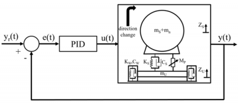
Figure 4. Block diagram of PID controller of liquid circle tank truck
in which, yr(t) – Reference signal; y(t) – Response of the system; u(t) – Control signal; e(t) – Difference between reference signal and system response. Currently, PID controllers are widely used in the optimization of suspension systems on commercial cars [22, 23]. For specialized vehicles such as carrying liquids, it is very little. Therefore, in this study, application of PID controller for vehicle suspension system to reduce the rollover tendency of liquid tanker trucks which is presented in Figure 4.
To evaluate the rollover stability characteristics of liquid tank trucks, the study uses the redistribution coefficient of vertical reaction at the two sides of wheel which is called LTR (lateral load transfer ratio) [24, 25]. This parameter is determined by the ratio between the reaction difference of the two wheels to their total reaction as follows:
$L T R_i=\frac{F_{z i 2}-F_{z i 1}}{F_{z i 2}+F_{z i 1}}$ (9)
With Fzi1 and Fzi2 are the vertical reactions acting on the left and right wheels of the i axle, respectively.
When the load is evenly distributed on the i axle, the LTRi is equal to 0. When there is separation of wheels on the i axle from the road, the LTRi is ±1 (the "+" sign corresponds to the i1 wheel separation, it means the vehicle roll to the right, the left wheel does not contact the road surface and opposite to the "-" sign corresponds to the i2 wheel separation).
In this study, the single-axle vehicle model used LTR coefficient to determine the unstable state of rollover (when the multi-axle vehicle has been combined into an axle, corresponding to the half vehicle model of rollover stability). In this study, the single-axle vehicle model uses LTR coefficient to determine the unstable state of rolling over (when the multi-axle vehicle has merged into one axle, corresponding to the stable half-car model). To optimize LTR value by using PID for active suspension system, the parameters in the LTR index must be measured or calculated from sensor signals or by synthesis method [26]. Based on the research results in the studies [27, 28], this LTR index is calculated using the above methods according to the following formula:
$L T R=\frac{2 K_{\mathrm{W}} \psi_U d_U+2 C_{\mathrm{w}} \dot{\psi}_U d_U}{\left(m_S+m_L+m_U\right) g}$ (10)
According to Eqs. (6) and (9), the LTRi index can be converted into a new load transfer ratio value (LTRN) as follows:
$L T R N=\frac{K_{\mathrm{w}} \psi_U d_U-C_{\mathrm{w}} \dot{\psi}_U d_U}{0.5 g\left(m_S+m_L+m_U\right)-K_{\mathrm{w}} Z_U-C_{\mathrm{w}} \dot{Z}_U}$ (11)
The LTRN index proposed in Eq. (11) takes into account the displacement and velocity of the unsprung mass. Therefore, it is necessary to consider the compatibility of this value with the LTR value in Eq. (10).
In addition, when analyzing the main index used to evaluate rollover stability, the LTR coefficient, it is also necessary to consider the secondary factor, the absolute value of the roll angle (TRA) of the suspension because the roll state also occurs when the difference of the tilt angle between the suspended and unsuspended mass (ΨS - ΨU) is greater than the allowable limits ($7 \div 8$ degrees) although this angle is small [29, 30]. Therefore, the study only needs to consider the suitability of the two indices LTR and LTRN [26].
To evaluate the effectiveness of using a PID controller for an active suspension system to enhance the roll stability of a liquid tank truck, it is first necessary to determine the liquid level that tends to cause the vehicle to roll over. Next, consider the suitability of using the LTRN index, and finally, analyze the vehicle's rollover stability when using PID.
In the process of changing the direction of motion of the circular tank truck carrying liquid, the liquid will fluctuate depending on the amount of water contained in the tank. Therefore, when evaluating the rolling stability characteristics of the vehicle, the research only focuses on the level of the contents in the tank at the ratios between the liquid level height h and the diameter of the tank as follows: h = 0, D/4, D/2, 3D/4, D in case the vehicle turns around and changes lanes.
The study began with determining the fluid level that tends to cause rollovers through the LTRN index and the roll angle in two cases of changing directions of motion.
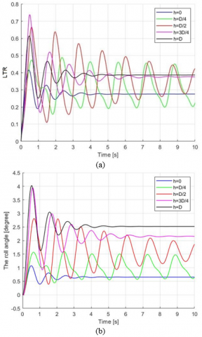
Figure 5. The LTRN index (a) and TRA (b) in steady turning
In case of steady turning means that the vehicle moves with unchanged speed and turning radius, when the closer the LTRN index is to ±1, the higher the tendency for a rollover to occur. The simulation results in Figure 5 show that at the height of the liquid level in the tank, D/2 and 3D/4 are the two most dangerous positions. Although the TRA value is still within the safe range, it stills pay attention to position 3D/4 and full load because it is the largest.
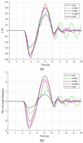
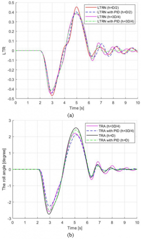
Figure 6 simulates the case of a vehicle changing lanes, similar to Figure 5, the highest LTRN index at the liquid level height is D/2 and 3D/4. The TRA value is highest at 3D/4 and full load, but this index has not yet exceeded the allowable value.Therefore, in the two cases of motion of a circular liquid tank truck, at the liquid level with a height equal to 1/2 and 3/4 compared to the tank diameter, there is a tendency to cause rollover instability.
The results in Figures 5 and 6 are obtained from simulation calculations of the vehicle dynamics model. Therefore, it is necessary to compare the LTRN index with actual measured results at dangerous liquid levels, these results are presented in Figure 7.
Figure 6. The LTRN index (a) and TRA (b) in lane change maneuver
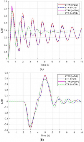
In the case shown in Figure 7a, when the tank truck turns stably, the two indicators LTR and LTRN can see the error at liquid level D/2 is 9.7%, at 3D/4 is 8.4%. Similarly, in the case of a vehicle moves lane change maneuver as shown in Figure 7b, the error is 2.1% at D/2 and 1% at 3D/4, respectively. This error is due to LTRN takes into account the displacement and displacement velocity of the unsuspended mass. On the other hand, these two factors actually also affect the tendency to the vehicle rolling and in the research results [26] show this error is still allowed, so the LTRN index matches the LTR index. Besides, the phenomenon of vehicle rollover only occurs in a short period of time, so the control to prevent this trend from occurring requires quick response. When the tank truck tends to roll, the LTRN value will reach the rollover threshold faster than the LTR and the active suspension system will exert its full capacity. Therefore, the LTRN index is used to evaluate the enhancement of rollover stability of liquid circle tank trucks when the vehicle changes movement direction.
Figure 7. Comparative simulation results between LTR-LTRN in steady turning (a) and lane change maneuver (b)
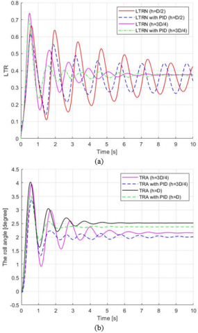
To evaluate the ability to enhance the overturning stability characteristics of liquid circular tank trucks when using and not using PID controller, or in other words, comparing between passive suspension system (without PID) and active suspension system (with PID) by simulation results comparing LTRN and TRA which are depicted in Figures 8 and 9 in the vehicle turns stably and changes lanes, respectively.
The lateral load transfer ratio index LTRN is only in the ±1 range which it is very small so when this value increases or decreases, it is not large, but to have such a change, active suspension control is required by PID to create a very large anti-roll moment. The results in Figure 8 show that when the active suspension system uses a PID controller, the LTRN and TRA values decrease greatly.
On the contrary, in Figure 9, these two values decrease very little. Almost all simulated TRA values in Figures 8 and 9 satisfy the evaluation criteria. Therefore, research needs to pay attention to the vehicle's dangerous LTRN index. The above results also show when increasing the anti-rolling moment for the vehicle, the fluid moving inside the tank and the impact on the vehicle's body is reduced, so when turning with a constant radius and speed, the fluid will tilt to one side. Then it oscillates back and forth with a decreasing cycle, the force acting on both sides of the wheel will decrease due to the use of an active suspension system with PID control, leading to a decrease in the LTRN value. Similar to the case of changing lanes as simulated, when the fluid oscillates back and forth, in addition to the vehicle moving back and forth at high speed, the fluid does not oscillate at its full amplitude, so its impact force causes for small cars, so when equipped with a PID controller, it reduces slightly compared to the above case. The specific change values are displayed in Table 2.
Figure 8. The LTRN index (a) and TRA (b) with and without PID controller in steady turning
Table 2. Changes in magnitude indices of LTRN and TRA
|
Change of Direction State |
Index |
Liquid Level |
Without PID |
With PID |
Reduction Rate (%) |
|
Steady turning |
LTRN |
D/2 |
0.665 |
0.6161 |
7.4 |
|
|
3D/4 |
0.738 |
0.697 |
5.6 |
|
|
TRA |
3D/4 |
3.950 |
3.380 |
14.4 |
|
|
|
Full load |
4.030 |
3.510 |
12.9 |
|
|
Lane change maneuver |
LTRN |
D/2 |
0.4695 |
0.4402 |
6.2 |
|
|
3D/4 |
0.4465 |
0.4161 |
6.8 |
|
|
TRA |
3D/4 |
2.590 |
2.260 |
12.7 |
|
|
|
Full load |
2.750 |
2.50 |
9.1 |
Figure 9. The LTRN index (a) and TRA (b) with and without PID controller in lane change maneuver
This shows that in the case of stable turning, the PID controller works more effectively and optimally than in the case of lane changing. Vehicle lane changes rarely occur, only when the vehicle encounters an obstacle or wants to overtake another vehicle. When the car turns around, this happens often. Therefore, if the PID works well, the ability to enhance the vehicle's roll stability is more guaranteed.
This study proposes a method to enhance the lateral stability characteristics of a circular tank truck containing liquids by using a PID controller for the active suspension system. The next research direction to clarify the application of PID is to optimally control the input current to the hydraulic valve actuator, and the output is the force applied to the suspension system to optimize the stiffness of the stabilizer bar, as in research [29]. In addition, the proposed lateral transfer index is used to evaluate it in accordance with the LTN index determined from reality. The simulations are performed using a multi-point dynamic model of a circular liquid tank truck combined with quasi-static, Lagrange methods, and D'Alembert's principle for calculations.
The results obtained in the time domain show that the effectiveness of the PID controller has improved the vehicle's roll stability characteristics through the LTRN value. At a liquid level of 0.8m and 1.2m compared to the tank diameter, the LTRN is reduced by 7.4% and 5.6% in the case of stable turning and 6.2% and 6.8% in the case of lane changing, respectively.
In fact, drivers carrying liquids in circular tanks need to be aware of dangerous liquid levels when changing directions of movement, as mentioned in the study. If it is necessary to carry liquid, it must be fully loaded and must drain all liquid when not fully used to limit fluctuations of the liquid inside. Besides, Eq. (5) shows that the driver needs to reduce the vehicle speed when turning or increase the turning radius to keep the lateral acceleration as small as possible. In addition, research serves the design and manufacture of active suspension system structures to increase vehicle stability by designing a hydraulic valve assembly with a PID to control the stabilizer bar.
This research is funded by Industrial University of Ho Chi Minh City (IUH) for research project under decision No.162/QĐ-ĐHCN with code 22/2ĐL01.
|
mS |
The sprung mass, kg |
|
mU |
The unsprung mass, kg |
|
mL |
Mass of liquid, kg |
|
hS |
Distance from center of roll to center of gravity of vehicle, m |
|
hU |
Distance from center of roll to center of the unsprung mass, m |
|
KW, CW |
Cornering stiffness, roll stiffness of tyre, N.m-1, Ns.m-1 |
|
KS, CS |
Stiffness, Damping of suspension, N.m-1, Ns.m-1 |
|
KR |
Stiffness of the stabilizer bar, N.m-1 |
|
IS |
The inertia moment of mS, kg.m-2 |
|
IU |
The inertia moment of mU, kg.m-2 |
|
g |
Gravitational acceleration, m.s-2 |
|
PL |
Centrifugal force of the liquid, N |
|
PS |
Centrifugal force of the sprung mass, N |
|
PU |
Centrifugal force of the unsprung mass, N |
|
dS |
Dimension from the roll axis of sprung mass to one side of suspension, m |
|
dU |
Dimension from the roll axis of unsprung mass to one side of wheel track, m |
|
dL |
Distance from center of tank to center of liquid, m |
|
D |
Diameter of tank, m |
|
L |
Length of tank, m |
|
R |
Turning radius, m |
|
v |
Vehicle speed, m.s-1 |
|
Greek symbols |
|
|
ΨS |
Tilt angle of sprung mass, degree |
|
ΨU |
Tilt angle of unsprung mass, degree |
|
αL |
Oscillation angle of the liquid mass, degree |
[1] National Center for Statistics and Analysis. (2023). Early Estimates of Motor Vehicle Traffic Fatalities and Fatality Rate by Sub-Categories in 2022. National Highway Traffic Safety Administration, Report no. DOT HS 813 448.
[2] Meshkatifar, J., Esfahanian, M. (2015). Optimal roll center height of front mcpherson suspension system for a conceptual class a vehicle. Journal of Applied and Computational Mechanics, 1(1): 10-16. https://doi.org/10.22055/JACM.2014.10578
[3] Sree Ram, S.A., Raja, P., Sreedaran, K. (2017). Optimization of rollover stability for a three-wheeler vehicle. Advances in Manufacturing, 5: 279-288. https://doi.org/10.1007/s40436-017-0191-8
[4] Pourasad, Y., Mahmoodi-k, M., Oveisi, M. (2016). Design of an optimal active stabilizer mechanism for enhancing vehicle rolling resistance. Journal of Central South University, 23: 1142-1151. https://doi.org/10.1007/s11771-016-0364-9
[5] Quguang, G., Mingmao, H., Yu, S., Hongyi, Z., Hua, T. (2018). Research on rollover prevention stability of heavy truck based on PID. In IEEE 4th International Conference on Control Science and Systems Engineering (ICCSSE): Wuhan, China, 101-105. https://doi.org/10.1109/CCSSE.2018.8724808
[6] Gao, J., Yin, C., Yuan, G. (2022). Warning and active steering rollover prevention control for agricultural wheeled tractor. PLoS ONE, 17(12): e0280021. https://doi.org/10.1371/journal.pone.0280021
[7] Winkler, C.B. (2000). Rollover of heavy commercials vehicles. The UMTRI Research Review, Ann Arbor, 31(4).
[8] Nguyen, X.N., Tran, V.N., Vu, V.T., Dang, T.P. (2022). Evaluation of rollover stability of liquid tank truck in the lane change. In International Conference on Engineering Research and Applications, Thai Nguyen, Vietnam, pp. 537-542. https://doi.org/10.1007/978-3-031-22200-9_59
[9] Zheng, X., Zhang, H., Ren, Y., Wei, Z., Song, X. (2017). Rollover stability analysis of tank vehicles based on the solution of liquid sloshing in partially filled tanks. Advances in Mechanical Engineering, 9(6): 1687814017703894. https://doi.org/10.1177/1687814017703894
[10] Kang, X., Rakheja, S., Stiharu, I. (1999). Optimal tank geometry to enhance static roll stability of partially filled tank vehicles. SAE Transactions, 108(2): 542-553.
[11] Shojaeefard, M.H., Talebitooti, R., Yarmohammadi-Satri, S. (2013). Optimizing elliptical tank shape based on real-coded genetic algorithm. International Journal of Advanced Design and Manufacturing Technology, 6(4): 23-29. https://doi.org/10.13140/2.1.3994.4323
[12] Yu, D., Chu, J. (2019). Study on roll-stability model optimization for partially filled tanker trucks. Advances in Mechanical Engineering, 11(4): 1687814019837805. https://doi.org/10.1177/1687814019837805
[13] Tran, V.N., Nguyen, X.N., Vu, V.T., Dang, T.P. (2022). Rollover stability analysis of liquid tank truck taking into account the road profiles. Journal of Applied Engineering Science, 20(4): 1133-1142. https://doi.org/10.5937/jaes0-36578
[14] Li, X., Zheng, X., Ren, Y., Wang, Y., Cheng, Z. (2013). Study on driving stability of tank trucks based on equivalent trammel pendulum for liquid sloshing. Discrete Dynamics in Nature and Society, 659873. https://doi.org/10.1155/2013/659873
[15] Jiang, K., Pavelescu, A., Victorino, A., Charara, A. (2014). Estimation of vehicle's vertical and lateral tire forces considering road angle and road irregularity. In IEEE 17th International Conference on Intelligent Transportation Systems (ITSC), Qingdao, China, pp. 342-347. https://doi.org/10.1109/ITSC.2014.6957714
[16] Moreno, G., Vieira, R., Martins, D. (2018). Highway designs: Effects of heavy vehicles stability. DYNA, 85(205): 205-210. https://doi.org/10.15446/dyna.v85n205.69676
[17] He, Y., Ren, J. (2013). A comparative study of car-trailer dynamics models. SAE International Journal of Passenger Cars - Mechanical Systems, 6(1): 177-186. https://doi.org/10.4271/2013-01-0695
[18] Sağlam, F., Ünlüsoy, Y.S. (2015). Analysis and design of passive and active interconnected hydro pneumatic suspension systems in roll plane. ICENS 2015 International Conference on Engineering and Natural Sciences, Skopje, Macedonia.
[19] Zhu, S., He, Y. (2015). Articulated heavy vehicle lateral dynamic analysis using an automated frequency response measuring technique. International Journal of Vehicle Performance, 2(1): 30-57. https://doi.org/10.1504/IJVP.2015.074121
[20] Nguyen, X.N., Tran, T.T. (2023). Rollover stability dynamic analysis of passenger vehicle in moving conditions. Mathematical Modelling of Engineering Problems, 10(1): 149-154. https://doi.org/10.18280/mmep.100116
[21] Shahid, Y., Wei, M. (2020). Comparative analysis of different model-based controllers using active vehicle suspension system. Algorithms, 13(1): 10. https://doi.org/10.3390/a13010010
[22] Tian, M., Nguyen, V. (2020). Control performance of suspension system of cars with PID control based on 3D dynamic model. Journal of Mechanical Engineering, Automation and Control Systems, 1(1): 1-10. https://doi.org/10.21595/jmeacs.2020.21363
[23] Jamil, M., Zafar, S., Gilani, S.O. (2018). Designing PID controller based semi-active suspension system using MATLAB simulink. SCITA 2017, Lecture Notes of the Institute for Computer Sciences, Social Informatics and Telecommunications Engineering, Jeddah, Saudi Arabia, pp. 282-295. https://doi.org/10.1007/978-3-319-94180-6_27
[24] Larish, C., Piyabongkarn, D., Tsourapas, V., Rajamani, R. (2013). A new predictive lateral load transfer ratio for rollover prevention system. IEEE Transactions on Vehicular Technology, 62(7): 2928-2936. https://doi.org/10.1109/TVT.2013.2252930
[25] Shin, D., Woo, S., Park, M. (2021). Rollover index for rollover mitigation function of intelligent commercial vehicle’s electronic stability control. Electronics, 10(21): 2605. https://doi.org/10.3390/electronics10212605
[26] Zheng, L., Lu, Y., Li, H., Zhang, J. (2023). Anti-rollover control and HIL verification for an independently driven heavy vehicle based on improved LTR. Machines, 11(1): 117. https://doi.org/10.3390/machines11010117
[27] Wang, R., Xu, X., Chen, S., Guo, N., Yu, Z. (2023). Vehicle rollover warning and control based on attitude detection and fuzzy PID. Applied Sciences, 13(7): 4339. https://doi.org/10.3390/app13074339
[28] Zhao, W., Ji, L., Wang, C. (2019). H∞ control of integrated rollover prevention system based on improved lateral load transfer rate. Transactions of the Institute of Measurement and Control, 41(3): 859-874. https://doi.org/10.1177/0142331218773527
[29] Vu, V.T., Sename, O., Dugard, L., Gaspar, P. (2017). Enhancing roll stability of heavy vehicle by LQR active anti-roll bar control using electronic servo-valve hydraulic actuators. Vehicle System Dynamics, 55(9): 1405-1429. https://doi.org/10.1080/00423114.2017.1317822
[30] Vu, V.T. (2017). Enhancing the roll stability of heavy vehicles by using an active anti-roll bar system. PhD Dissertation. Grenoble Alpes University. France.