Asnil Asnil*![]() | Krismadinata Krimadinata
| Krismadinata Krimadinata![]() | Erita Astrid
| Erita Astrid![]() | Irma Husnaini
| Irma Husnaini
© 2024 The authors. This article is published by IIETA and is licensed under the CC BY 4.0 license (http://creativecommons.org/licenses/by/4.0/).
OPEN ACCESS
The incremental conductance method is susceptible to overshoot, oscillation, convergence errors, and the inability to adapt to rapidly changing conditions; therefore, innovation is required to ensure that this algorithm operates efficiently. This study investigates how the incremental conductance algorithm can be modified to enhance its performance, particularly in situations involving rapid environmental changes. The algorithm's performance is evaluated through simulation and subsequently compared to conventional methods and incremental conductance methods developed by previous researchers to determine how much performance increase can be achieved using the modified algorithm. The simulation results show that the second improved technique may significantly eliminate oscillations during maximum power point (MPP) tracking while also speeding up the convergence time. The results reveal that the proposed algorithm achieves an efficiency of 98.83%, which is higher than the conventional and first modified algorithms, which have efficiency values of 92.04% and 97.84%, respectively. Therefore, the second modification outperforms the other algorithms in terms of oscillation and efficiency.
incremental conductance, convergence, oscillation, overshoot, tracking efficiency
Renewable and sustainable energy sources have emerged as an imperative substitute for fossil fuels, which are associated with numerous adverse environmental consequences, including climate change and air pollution manifested as CO2 emissions [1, 2]. Among renewable energy sources, solar energy is considered the most viable renewable energy source for addressing these challenges due to its abundant availability [3, 4], pollution-free, and requires little maintenance [5, 6]. Nonetheless, optimizing photovoltaic (PV) energy output has become challenging for researchers [7]. The amount of energy produced by PV is determined by the solar radiation conditions and the temperature of the PV cells. The intensity of solar radiation directly correlates with the amount of energy generated by photovoltaic (PV) system. Many methods have been proposed to maximize solar energy absorption through PV, including reconfiguring the PV system [8, 9], implementing a solar tracker system [10, 11], and employing the maximum power point tracking (MPPT) concept [12-14].
The MPPT method exhibits distinct advantages in comparison to other approaches when it comes to optimizing PV solar energy absorption. It does not require reconfiguring the PV system and adding a device to move the PV surface in the direction of sunlight. As a result, the presence of MPPT is critical because it can improve output power efficiency by ensuring that the system works at the MPP and tracking new MPPs if environmental conditions change [15, 16]. MPPT techniques have been widely reported in the literature, with variations in tracking speed, convergence speed, oscillation, efficiency, and components used [17-21]. Numerous MPPT algorithms have been developed, including the fractional short circuit current (FOCC) technique [22, 23], the fractional open circuit voltage (FOCV) [24, 25], the fuzzy logic controller [26, 27], the perturbation and observation (P&O) [28, 29], and the incremental conductance (INC) [30, 31]. The P&O and INC approaches are still extensively utilized due to their straightforwardness and less expensive in implementation [32, 33]. However, the INC technique outperforms the P&O method in terms of efficiency and speed in tracking MPP in the face of rapid and dynamic environmental change [23, 34].
Under certain conditions, the INC technique is not able to operate very well or consistently in tracking Maximum Power Point (MPP) even though it is superior to others. In the case of partial shadows, the voltage-power curve will have numerous local maximum points [35]. The usage of the direct control approach is also one of the INC method's flaws, causing oscillations in the MPP due to the fixed step size utilized to update the duty cycle [36]. As a result, modifying the INC method is critical to improving performance, particularly system performance in conditions of fast variations in solar radiation values and temperature.
The purpose of this paper is to discuss adjustments to the INC approach to evaluate its performance in monitoring MPP under conditions of fast variations in solar light and temperature. The speed in tracking the MPP, overshoot, convergence speed, oscillations in the MPP, and efficiency are all investigated. The algorithm development refers to the previous studies about INC methods on MPP tracking systems, the conventional INC and the INC that has also been modified. This aims to observe how the proposed method can increase the algorithm's performance. Tests are conducted under conditions of varying radiation, with two distinctions: one involving constant temperature and another involving temperature changes. As a result, some parameters will be observed, including convergence time, oscillation value, overshoot, and efficiency, to analyze the algorithm’s performance.
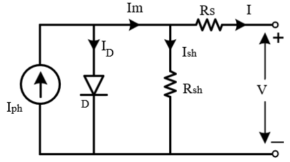
Figure 1 depicts the equivalent circuit of a PV cell, which comprises of a photocurrent source, diode, and resistor arranged in series and parallel.
Figure 1. The equivalent circuit of a PV cell
Mathematically, the model in Figure 1 can be expressed as Eq. (1) [37, 38].
$I=I_{p h}-I_s\left[\exp \left(\frac{V+R_s I}{n V_{t h}}\right)-1\right]-\frac{V+R_s I}{R_{s h}}$ (1)
$I_{p h}$ is the photocurrent originating from solar radiation influenced by the radiation value (G) and temperature (T), as can be seen in Eq. (2) [39].
$I_{p h}=\left[I_{s c}^*+k_i\left(T-T^*\right)\right] \frac{G}{G^*}$ (2)
where, $k_i$ is the short circuit current temperature coefficient, $I_{s c}^*$ the short circuit current value under Standard Test Conditions (STC), $G^*$ is the solar radiation constant with a value is $1000 \mathrm{~W} / \mathrm{m}^2$, and $T^*$ is the temperature value of the $\mathrm{PV}$ cell which is $298 \mathrm{~K}$. Moreover, $I_s$ is the reverse saturation current of the diode, $\mathrm{V}$ is the value of the PV output voltage, $R_s$ and $R_{s h}$ represent the resistance that is installed in series and parallel respectively, and $n$ is the ideal factor of the diode.
To calculate a thermal stress value $\left(V_{t h}\right)$ uses the equation $V_{t h}=\frac{K T}{q}$. Here, $K$ is Boltzmann's constant with a value of $1.3806503 \mathrm{e}-23 \mathrm{~J} / \mathrm{K}, q$ is the electron charge value with a value of $1.60217646 \mathrm{e}-19 \mathrm{C}$, and $T$ is the temperature of the PV cell in Kelvin $(\mathrm{K})$. The output power value can be acquired through Eq. (3) and in determining the value of $P_{m p p}$ can be used Eq. (4).
$P=V \times\left(I_{p h}-I_s\left[\exp \left(\frac{V+R_s I}{n V_{t h}}\right)-1\right]-\frac{V+R_s I}{R_{s h}}\right)$ (3)
$\begin{gathered}P_{m p p}=V_{m p p}\times\left(I_{p h}-I_s\left[\exp \left(\frac{V_{m p p}+R_s I_{m p p}}{n V_{t h}}\right)-1\right]-\frac{V+R_s I_{m p p}}{R_{s h}}\right)\end{gathered}$ (4)
If the current passing through the parallel resistance is substantially lower than the other currents then the resistance value can be ignored. If this argument is applied, Eq. (3) can be replaced with Eq. (5).
$I=I_{p h}-I_s\left[\exp \left(\frac{V+R_s I}{n V_{t h}}\right)-1\right]$ (5)
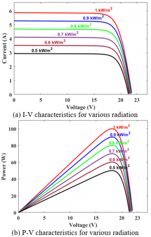
In this research, a monocrystalline type with the Solana brand SOL-M12100W series is used with the detail can be seen in Table 1 and the solar panel characteristic parameters in conjunction with the I-V and P-V characteristics curves seen in Figure 2.
Table 1. Electrical characteristics of SOL-M12100W
|
No |
Parameter |
Value |
|
1 |
Maximum Power (Pmax) |
100 Wp |
|
2 |
Optimum operating voltage (Vm) |
18.1 V |
|
3 |
Optimum operating current (Im) |
5.52 A |
|
4 |
Operating-circuit voltage (Voc) |
22.1 V |
|
5 |
Short-circuit current (Isc) |
5.86 A |
|
6 |
Temperature coefficients of Isc |
+0.06 %/0C |
|
7 |
Temperature coefficients of Voc |
-0.35 %/0C |
|
8 |
Numbers of cells |
36 pcs |
Figure 2. The PV characteristics under various radiation levels
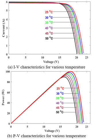
Using the parameters in Table 1, the results obtained from the simulation are modelled in Figures 2 and 3. Figure 2 depicts the effect of changes in radiation with a constant temperature, while Figure 3 depicts the effect of changes in temperature with a constant radiation value.
Figure 3. The PV characteristics under various temperature
From Figures 2 and 3, it can be seen that changes in the radiation value will affect the value of the solar panel output current. Meanwhile, variations in temperature values will affect the output voltage value of the solar panel.
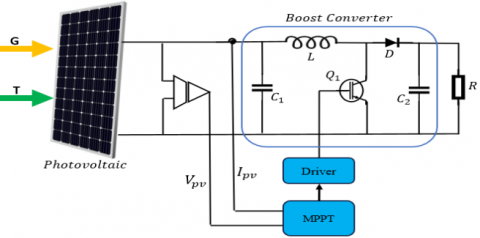
A DC-DC boost converter is used to increase the voltage resulted from PV with its configuration is presented in Figure 4.
Figure 4. The proposed photovoltaic system configuration
As seen in Figure 3, the energy produced by PV is influenced by solar radiation (G) and temperature (T). Two sensors are also added to measure the current and voltage. Eqs. (6)-(9) [7] can be used to calculate the boost converter's output voltage, input and output capacitor values, and inductance value.
$\frac{V_o}{V_{p v}}=\frac{1}{1-D}$ (6)
$C_1 \geq \frac{D}{8 \times f^2 \times L \times 0.01}$ (7)
$C_2 \geq \frac{D}{f \times 0.02 \times R}$ (8)
$L=\frac{D \times(1-D)^2 \times R}{r \times F}$ (9)
The boost converter's output and input voltage is $V_o$ and $V_{p v}$, respectively with duty cycle D. According to Eq. (6), increasing and reducing the input voltage can be accomplished by increasing and decreasing the duty cycle value. The parameter r is the current ripple ratio, which is typically between 0.3 and 0.5. Table 2 delineates the component values employed for the boost converter.
Table 2. The boost converter parameters
|
No |
Parameter |
Value |
|
1 |
L |
2.2 mH |
|
2 |
C1 |
47 uF |
|
3 |
C2 |
47 uF |
|
4 |
F |
31500 Hz |
|
5 |
R |
135 Ohm |
|
6 |
D |
0.7 |
Determining the component values, as shown in Table 2, depends on the desired converter design. A larger inductance value is expected to reduce oscillations in both current and voltage signals; however, this may result in slower response times and vice versa. Similarly, a higher switching frequency value is expected to increase efficiency. The type of transistor must also be considered because the performance of the chosen transistor influences power losses and system efficiency. The capacitor values are largely dependent on the availability in the market.
The INC method detects MPP by tracking the peak point of the P-V curve. In determining the location of the PV operating point, the INC method employs both additional and instantaneous conduction values. Eqs. (10) and (11) can be used to determine the location of the PV operating point [40].
$\frac{d I}{d V}=-\frac{I}{V}$ (10)
$\frac{d I}{d V}>-\frac{I}{V}$ (11)
$\frac{d I}{d V}<-\frac{I}{V}$ (12)
Eq. (10) indicates that the PV module operating point is on the MPP, Eq. (11) shows that the PV module operating point is to the left of the MPP, and Eq. (12) indicates that the PV module operating point is to the right of the MPP. The MPP point is where the output power reaches its maximum value. In this condition, the change in power due to the voltage changes is equal to zero. At this point, the current value achieves its maximum, and the change in current relative to voltage is also zero which means the system has reached its maximum power point. This state indicates that the next voltage adjustment will not result in a considerable change in current, and the power value will reach its peak. Eq. (10) and Eq. (11) are derived from the slope of the P–V curve when the MPP is zero, as illustrated in Eq. (13).
$\frac{d P}{d V}=0$ (13)
If Eq. (13) is rearranged, the following equations will be obtained.
$\frac{d P}{d V}=I \frac{d V}{d V}+V \frac{d I}{d V}$ (14)
$\frac{d P}{d V}=I+V \frac{d I}{d V}$ (15)
$I+V \frac{d I}{d V}=0$ (16)
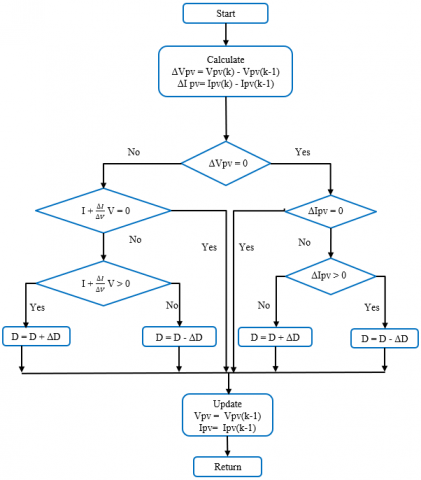
Eq. (16) serves as the basis for the MPP calculation in the INC algorithm, which is illustrated in Figure 5. The reduction of the converter working cycle is required if Eq. (11) is satisfied, and conversely, if Eq. (12) is satisfied. If Eq. (13) is satisfied, the converter's duty cycle remains constant.
Figure 5. Flowchart of INC method
As shown in Figure 4, one of the flaws of the INC algorithm is susceptible to oscillations in a steady state, which is illustrated in Figure 6. Additionally, the algorithm's performance degrades significantly with an increase in solar radiation [41, 42]. In addition, the performance of the INC algorithm can also be influenced by noise and inaccuracies in measurements. Noises in current and voltage can induce oscillations. This can disrupt system voltage stability when the algorithm operates to reach MPP. This also will affect the convergence time. Another effect, noises and measurement errors provide challenges for algorithms in accurately discerning between substantial changes and minor fluctuations. As a result, the INC algorithm's performance must be improved by implementing improvements aimed at assuring proper GMPP tracking and addressing algorithm faults in making judgments when solar radiation values grow.
The objective of modifying the conventional INC algorithm is to enhance the efficiency of the MPP tracking process. In this research, two modified algorithm is compared with the conventional ones to observe their performance in tracking MPP. Even though tracking MPP with conventional algorithms is more effective under uniform radiation conditions somehow oscillations in steady-state conditions can impact MPPT in the event of abrupt changes in radiation conditions. This algorithm finds it difficult to distinguish between the effects of rapidly changing radiation and changes in the location of the MPP. Two modifications are carried out here as explained in Figures 5 and 6.
5.1 The 1st modified incremental conductance method
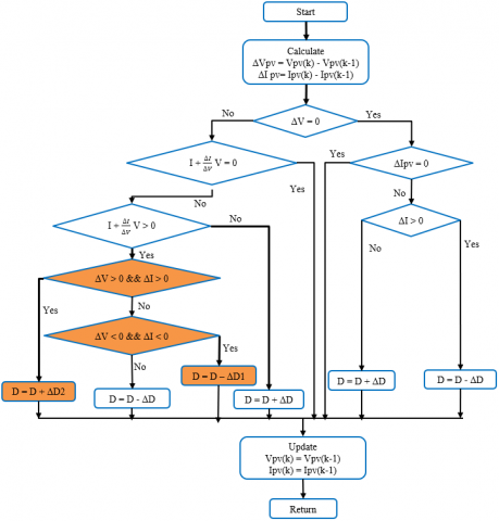
The INC approach, described in reference [39], employs an algorithm depicted in Figure 6. The experimental results demonstrate that this approach outperforms the conventional INC algorithm. This algorithm can enhance the performance of Photovoltaic systems, particularly in dynamic conditions by mitigating significant power losses. Apart from that, this algorithm can also increase tracking efficiency by five percent. The algorithm's workflow is illustrated in Figure 6, with the modified part highlighted in shade. The values used in this algorithm for Δd = 0.0002, Δd1 = 0.0005, and Δd2 = 0.00009.
f the voltage disturbance leads to current variation with the same sign, a sudden change in irradiance is imposed on the solar array. Alternatively, the conventional INC approach is adequate for efficiently monitoring the optimal MPP. Furthermore, the modified INC MPPT technique employs varying step sizes in the perturbation of the PV array, depending on the position of MPP on the P-V curve. Consequently, when the operating point is closer to MPP, the voltage perturbation step size becomes smaller, as depicted in Figure 6.
Figure 6. The algorithm models developed in the 1st modified INC [39]
5.2 The 2nd modified INC algorithm
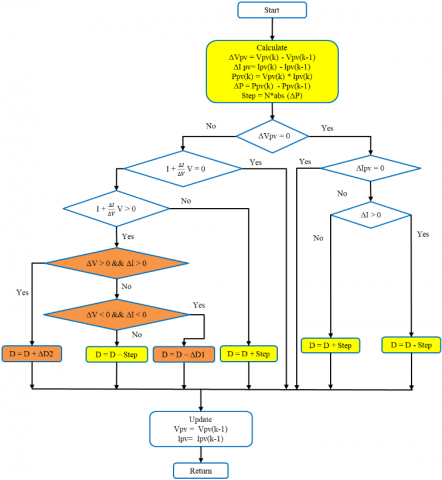
The 2nd modified INC in this study is a result of modification done in the 1st INC algorithm illustrated in Figure 6. This method is further developed by referring to the Variable Step Size (VSS) concept which can be seen in Figure 7. When there is a change in the radiation value, there will be a quite large change in the power (dP) value while the change in the voltage value is relatively small. Usually, VSS is influenced by provisions that can cause changes in the duty cycle value that are large enough to shift the operating point away from the new MPP. Changes in power values can cause the MPPT algorithm to take longer to reach a new MPP, consequently leading to a reduction in the tracking efficiency value. Hence, this study posits that the VSS value is solely determined by the power change value (dP), as defined in Eq. (17). N is a switching factor to adjust the VSS value to improve performance, particularly tracking accuracy and convergence speed.
$\Delta D=N *|d P|$ (17)
The algorithm depicted in Figure 7 is essentially similar to the approach illustrated in Figure 6. If there is a fluctuation in voltage that leads to a change in current, indicating that the system is operating in the presence of varying radiation, the procedure resembles the one depicted in Figure 6. Alternatively, if this requirement is not met, the standard INC method can be used effectively, indicating uniform or equal radiation circumstances. The algorithm depicted in Figure 6 was devised in a manner similar to that shown in Figure 7, where alterations in current and voltage result in modifications in power. This method utilises the notion of VSS, where the step value for each change in the duty cycle is determined by variations in the power output of the solar panel. The modifications implemented by the researcher are indicated by the yellow shading in Figure 7.
Figure 7. The algorithm model of the proposed method
This section discusses the performance of MPPT algorithms with three different INC techniques by observing their ability to adjust to changes in external circumstances, such as variations in radiation and temperature. The algorithm performance is observed through such parameters such as convergence speed, oscillation, overshot and efficiency. Experiments are conducted to examine the effects of varying radiation conditions while keeping the temperature constant, as well as to investigate the combined effects of changing radiation and temperature. Conducting tests at a consistent temperature is done to determine if the algorithm can effectively reach MPP based on variations in radiation levels. Any alteration in the radiation and temperature values will result in a corresponding reduction in the output power value. The temperature under constant and fluctuating conditions is used to determine how solar panels can sustain electrical energy conversion efficiency. Low and constant temperatures will improve efficiency when converting solar energy into electrical energy. Conversely, high temperatures can lead to a reduction in the efficiency of converting electrical energy due to the heat-induced rise in resistance within the solar panels. In addition, high temperatures might diminish the voltage and current produced by solar panels, while significant temperature fluctuations can heighten the likelihood of physical harm to the panels. Solar panels are often utilized to function within a specific temperature range. Optimizing the temperature within a certain range can enhance the efficiency and durability of solar panels.
Testing is conducted in order to determine if the developed algorithm can still attain MPP in response to variations in radiation levels. This performance is visible because variations in radiation and temperature values occur frequently in real-world situations. The measurement results are shown in Figures 8-11.
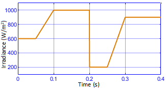
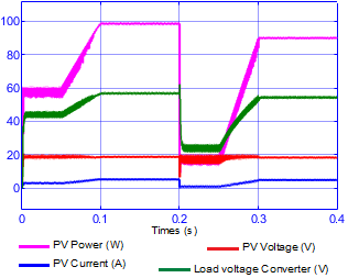
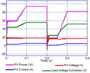
(a) Irradiance change pattern
(b) Performance of system with INC conventional
(c) Performance of systems based on modification algorithm
(d) Performance of systems based on proposed algorithm
Figure 8. System performance under various irradiation and fixed temperatures
Figure 8 depicts the system's performance simulation results using the conventional INC technique, the first modified INC algorithm [39], and the proposed INC algorithm with changing radiation parameters and a fixed temperature of 25℃. Figure 8(a) is a pattern of changes in radiation values starting from 600 W/m2 rising to 1000 W/m2 and then suddenly dropping to 200 W/m2 which then increases again to 900 W/m2. Figure 8(b) depicts the conventional INC method system performance in terms of PV output power, voltage, current, and load voltage from the converter. In the beginning, there are quite large oscillations in the output power signal and load voltage on the converter, but the oscillations decrease when the radiation reaches the maximum value. When radiation drops drastically then overshot occurs and oscillations appear in the PV output power signal, PV voltage, and load voltage on the converter, which then diminish as the radiation value increases. The oscillations arise from variations in sunlight intensity and the shadows that obstruct the sunlight from reaching the solar panel's surface. Oscillations can cause fluctuations in the output power of solar panels, leading to disturbances in the load and diminishing system stability. In addition, the hysteresis effect of the power converter employed in the MPPT system might induce abrupt fluctuations in the current and voltage of the solar panel's output. This condition will affect system stability and produce undesirable fluctuations in output power. Moreover, Figure 8(c) depicts the system performance utilizing the modified INC algorithm shown in Figure 6. The duty cycle increments used for this modified algorithm are ∆D = 0.00003, ∆D1 = 0.00005 and ∆D2 = 0.000007. The results of this algorithm modification can improve the performance of conventional algorithms, especially in reducing oscillation values. This algorithm can also increase the output power value of PV, especially under maximum radiation conditions. Figure 8(d) is an illustration of the performance of the system using the modified INC algorithm as in Figure 7. Overall, the two modified algorithm have better performances. Oscillations in output power, especially at steady state are deemed to be non-existent. However, there are weaknesses to both of these methods. This can be seen when the radiation value drops drastically causing overshoot with different values.
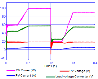
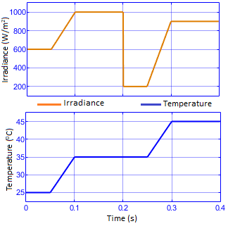
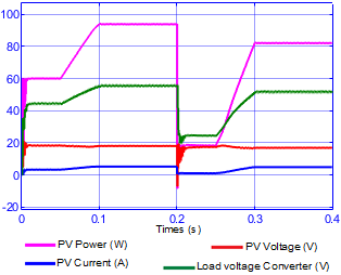
Figure 9 shows the results of system performance when variations in radiation and temperature values occur. Figure 9(a) depicts the variation pattern of changes in radiation and temperature values.
(a) irradiance change pattern
(b) Performance of systems with INC conventional
(c) Performance of systems based on modification algorithm
(d) Performance of systems based on proposed algorithm
Figure 9. System performance under various irradiation and fixed temperatures
Figure 9(b) is an illustration of the system performance using the conventional INC algorithm. The description of the resulting performance is not much different from the performance in Figure 8(b), but the main difference is that there is a decrease in the power produced by PV. The system's performance utilizing the conventional method under changing radiation conditions and constant temperature is 98.92 W at maximum radiation but reduces to 93.33 W when radiation conditions and temperature change. This condition also occurs in the two modified algorithms, where changes in temperature and radiation cause a decrease in electrical power output. In general, the performance difference between changing radiation conditions and constant temperature and changing radiation and temperature conditions is not significant. The obvious difference is that the oscillations that occur differ for each method, with the lowest oscillation value occurring when the second modified algorithm is used.
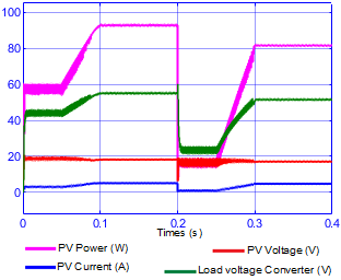
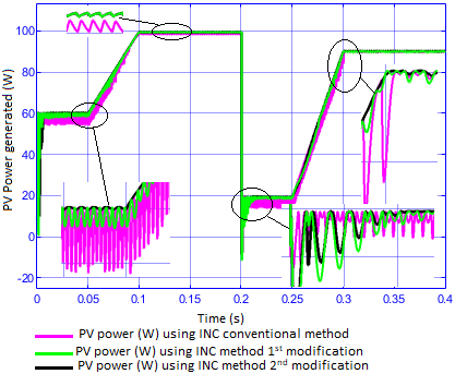
Figure 10. Comparison of output power from PV using different INC algorithm under changing radiation conditions and constant temperature
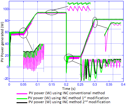
Figure 11. Comparison of output power from PV using different INC algorithm under changing radiation and temperature conditions
Figure 10 illustrates the comparison of the output power signal from each algorithm used in the research under different radiation conditions while maintaining a constant temperature. The second algorithm modification exhibits significantly improved oscillation, overshoot, and convergence times.
The output power signal from PV, as determined by the three MPPT algorithms under varying radiation and temperature conditions, is depicted in Figure 11. The results indicate that the PV power output diminishes under conditions of high radiation (900 W/m2 and 1000 W/m2), compared to conditions where the radiation changes and the temperature remains constant as in Figure 11. Nevertheless, under radiation conditions of 600 W/m2 and 200 W/m2, it is observed that The PV output power has not changed significantly.
The detailed performance of the three algorithms under changing radiation conditions and constant temperature can be seen in Table 3. In terms of convergence time, the second modified INC method outperforms the other two algorithms significantly. The convergence times for radiation levels of 600 W/m2 and 200 W/m2 cannot be determined due to the constantly changing output signal. However, the second modified algorithm achieved a convergence time of 0.0085 second. Similar to a maximum radiation value of 900 W/m2, the signal remains stable throughout, even at a radiation value of 1000 W/m2. In contrast, in the conventional algorithm and the first modified technique, the signal perpetually changes when confronted with radiation of 200 W/m2, resulting in the absence of a convergent point. The second modification algorithm, meanwhile, completes in 0.211 seconds. When evaluated concerning oscillation values, the performance of the second modified algorithm is superior to that of the other algorithms due to its comparatively lesser oscillations. In terms of MPP monitoring, the tracking efficiency of this algorithm also has better performance than that of the other algorithms.
From Table 4 it can be seen that the convergence time can be said to be no different from the previous condition and also in terms of oscillations of the second modified algorithm it is much smaller. In terms of tracking efficiency, the second modified algorithm is also much better than the other two algorithms. The significant difference between these two different conditions is that the output power value decreases when the radiation and temperature values change at all specified radiation levels. From the observed performance, the modified algorithm tends to have an occurrence of overshot which is greater than the conventional INC algorithm. This overshoot occurs when radiation suddenly drops to the lowest level, which in this study was set at a radiation value of 200 W/m2.
Table 3. The performance of three different INC techniques under radiation changes and temperature remains constant
|
MPPT Algorithm |
Convergence Time at Various Radiation Levels (seconds) |
Oscillations at Steady State at Various Radiation Levels (Watts) |
Max Overshoot (Watt) |
Average Tracking Efficiency (%) |
||||||
|
600 W/m2 |
1000 W/m2 |
200 W/m2 |
900 W/m2 |
600 W/m2 |
1000 W/m2 |
200 W/m2 |
900 W/m2 |
|||
|
INC Conventional |
Not Found |
Stable Condition |
Not Found |
Stable Condition |
5.9191 |
0.873 |
5.875 |
0.552 |
11.92 |
92.04 |
|
The 1st modified [39] |
1.898 |
0.273 |
1.48 |
0.679 |
30.99 |
97.84 |
||||
|
The proposed algorithm (2nd modified) |
0.0085 |
0.211 |
0.249 |
0.273 |
0.369 |
0.195 |
28.19 |
98.83 |
||
Table 4. The performance of three different INC techniques under the changes in radiation and temperature
|
MPPT Algorithm |
Convergence Time at Various Radiation Levels (seconds) |
Oscillations at Steady State (Watts) |
Max Overshoot (Watt) |
Average Tracking Efficiency (%) |
||||||
|
600 W/m2 |
1000 W/m2 |
200 W/m2 |
900 W/m2 |
600 W/m2 |
1000 W/m2 |
200 W/m2 |
900 W/m2 |
|||
|
INC Conventional |
Not Found |
Stable Condition |
Not Found |
Stable Condition |
5.9327 |
1.0121 |
5.01 |
0.6329 |
12.44 |
89.94 |
|
The 1st modified [39] |
2.0647 |
0.3986 |
1.331 |
0.191 |
29.56 |
93.39 |
||||
|
The proposed algorithm (2nd modified) |
0.0085 |
0.2105 |
0.1819 |
0.398 |
0.106 |
0.1887 |
27.06 |
94.47 |
||
The performance of the algorithm utilized in the research is tested under two different scenarios. The first condition is that radiation varies while temperature remains constant, while the second is that both radiation and temperature change. The test results reveal that the performance of the second modified algorithm according to the VSS concept outperforms the other two algorithms significantly. When it comes to convergence time, oscillation, and efficiency. The fundamental difference in the application of the algorithm in these two conditions can be seen from the PV output power where the output power is lower when the radiation and temperature conditions change. Another flaw revealed by the test findings is the existence of overshoot in the PV output power signal while utilizing the modified algorithm. This scenario occurs when the amount of radiation absorbed by PV reduces dramatically from the greatest level to the lowest level, which in this case is 200 W/m2. The algorithm devised is still uncomplicated, making it easily implementable in a photovoltaic system. The efficacy of this method can be further investigated by employing alternative converters or examining its consequences in regions with diverse radiation and temperature circumstances.
The authors would like to express their gratitude to the Institute for Research and Community Services of Universitas Negeri Padang under Penelitian Dasar Scheme (Grant No.: 1283/UN35.15/LT/2023).
[1] Khodair, D., Motahhir, S., Mostafa, H.H., Shaker, A., Munim, H.A.E., Abouelatta, M., Saeed, A. (2023). Modeling and simulation of modified MPPT techniques under varying operating climatic conditions. Energies, 16(1), 549. https://doi.org/10.3390/en16010549
[2] Asnil, A., Hazman, H. (2023). Real-time monitoring system using IoT for photovoltaic parameters. TEM Journal, 12(3): 1316-1322. https://doi.org/10.18421/TEM123-11
[3] Pervez, I., Antoniadis, C., Massoud, Y. (2022). Advanced limited search strategy for enhancing the performance of MPPT algorithms. Energies, 15(15): 5650. https://doi.org/10.3390/en15155650
[4] Martinez Lopez, V.A., Žindžiūtė, U., Ziar, H., Zeman, M., Isabella, O. (2022). Study on the effect of irradiance variability on the efficiency of the perturb-and-observe maximum power point tracking algorithm. Energies, 15(20): 7562. https://doi.org/10.3390/en15207562
[5] Akram, N., Khan, L., Agha, S., Hafeez, K. (2022). Global maximum power point tracking of partially shaded PV system using advanced optimization techniques. Energies, 15(11): 4055. https://doi.org/10.3390/en15114055
[6] Peng, B.R., Chen, J.H., Liu, Y.H., Chiu, Y.H. (2015). Comparison between three different types of variable step-size P&O MPPT technique. In International Conference on Computer Information Systems and Industrial Applications, pp. 964-966. https://doi.org/10.2991/cisia-15.2015.261
[7] Motahhir, S., El Ghzizal, A., Sebti, S., Derouich, A. (2017). MIL and SIL and PIL tests for MPPT algorithm. Cogent Engineering, 4(1): 1378475. https://doi.org/10.1080/23311916.2017.1378475
[8] Pendem, S.R., Mikkili, S. (2018). Modeling, simulation and performance analysis of solar PV array configurations (Series, Series–Parallel and Honey-Comb) to extract maximum power under Partial Shading Conditions. Energy Reports, 4: 274-287. https://doi.org/10.1016/j.egyr.2018.03.003
[9] Krishna, G.S., Moger, T. (2019). Improved SuDoKu reconfiguration technique for total-cross-tied PV array to enhance maximum power under partial shading conditions. Renewable and Sustainable Energy Reviews, 109: 333-348. https://doi.org/10.1016/j.rser.2019.04.037
[10] Elsayed, A.A., Khalil, E.E., Kassem, M.A., Huzzayin, O.A. (2021). A novel mechanical solar tracking mechanism with single axis of tracking for developing countries. Renewable Energy, 170: 1129-1142. https://doi.org/10.1016/j.renene.2021.02.058
[11] Vargas, A.N., Francisco, G.R., Montezuma, M.A., Sampaio, L.P., Acho, L. (2022). Low-cost dual-axis solar tracker with photovoltaic energy processing for education. Sustainable Energy Technologies and Assessments, 53: 102542. https://doi.org/10.1016/j.seta.2022.102542
[12] Ali, A., Almutairi, K., Padmanaban, S., et al. (2020). Investigation of MPPT techniques under uniform and non-uniform solar irradiation condition–A retrospection. IEEE Access, 8: 127368-127392. https://doi.org/10.1109/ACCESS.2020.3007710
[13] Bollipo, R.B., Mikkili, S., Bonthagorla, P.K. (2020). Critical review on PV MPPT techniques: Classical, intelligent and optimisation. IET Renewable Power Generation, 14(9): 1433-1452. https://doi.org/10.1049/iet-rpg.2019.1163
[14] Asnil, A., Nazir, R., Krismadinata, K., Sonni, M.N. (2023). A review of partial shading MPPT algorithm on speed, accuracy, and cost embedded. Diyala Journal of Engineering Sciences, 16(1): 1-14. https://doi.org/10.24237/djes.2023.16101
[15] Ahmed, N.A., Abdul Rahman, S., Alajmi, B. N. (2021). Optimal controller tuning for P&O maximum power point tracking of PV systems using genetic and cuckoo search algorithms. International Transactions on Electrical Energy Systems, 31(10): e12624. https://doi.org/10.1002/2050-7038.12624
[16] Li, L.L., Lin, G.Q., Tseng, M.L., Tan, K., Lim, M.K. (2018). A maximum power point tracking method for PV system with improved gravitational search algorithm. Applied Soft Computing, 65: 333-348. https://doi.org/10.1016/j.asoc.2018.01.030
[17] Mahmood, M.H., Ali, I.I., Ahmed, O.A. (2020). Comparative study of perturb & observe, modified perturb & observe and modified incremental conductance MPPT techniques for PV systems. Engineering and Technology Journal, 38(4A): 478-490. https://doi.org/10.30684/etj.v38i4a.329
[18] Ramesh, K., Ganesh, R.G., Reddy, S.L.V., Mahalakshmi, K., Suganya, S. (2018). An enhanced incremental conductance algorithm for photovoltaic system. Electronics, 22(1): 12-18. https://doi.org/10.7251/ELS1822012R
[19] Yildirim, M.A., Nowak-Ocłoń, M. (2020). Modified maximum power point tracking algorithm under time-varying solar irradiation. Energies, 13(24): 6722. https://doi.org/10.3390/en13246722
[20] Motahhir, S., El Hammoumi, A., El Ghzizal, A. (2018). Photovoltaic system with quantitative comparative between an improved MPPT and existing INC and P&O methods under fast varying of solar irradiation. Energy Reports, 4: 341-350. https://doi.org/10.1016/j.egyr.2018.04.003
[21] Bouksaim, M., Mekhfioui, M., Srifi, M.N. (2021). Design and implementation of modified INC, conventional INC, and Fuzzy Logic Controllers applied to a PV system under variable weather conditions. Designs, 5(4): 71.https://doi.org/10.3390/designs5040071
[22] Abdul-Razzaq, I.K., Sakr, M.M.F., Rashid, Y.G. (2021). Comparison of PV panels MPPT techniques applied to solar water pumping system. International Journal of Power Electronics and Drive System, 12(3): 1813-1822. https://doi.org/10.11591/ijpeds.v12.i3.pp1813-1822
[23] Dib, K., Chenni, R. (2018). A combined MPPT algorithm for photovoltaic systems based Arduino microcontroller. International Journal on Energy Conversion, 6(2): 66-75. https://doi.org/10.15866/irecon.v6i2.15090
[24] Baimel, D., Tapuchi, S., Levron, Y., Belikov, J. (2019). Improved fractional open circuit voltage MPPT methods for PV systems. Electronics, 8(3): 321. https://doi.org/10.3390/electronics8030321
[25] Hassan, A., Bass, O., Masoum, M.A. (2023). An improved genetic algorithm based fractional open circuit voltage MPPT for solar PV systems. Energy Reports, 9: 1535-1548. https://doi.org/10.1016/j.egyr.2022.12.088
[26] Ullah, K., Ishaq, M., Tchier, F., Ahmad, H., Ahmad, Z. (2023). Fuzzy-based maximum power point tracking (MPPT) control system for photovoltaic power generation system. Results in Engineering, 20: 101466. https://doi.org/10.1016/j.rineng.2023.101466
[27] Loukil, K., Abbes, H., Abid, H., Abid, M., Toumi, A. (2020). Design and implementation of reconfigurable MPPT fuzzy controller for photovoltaic systems. Ain Shams Engineering Journal, 11(2): 319-328. https://doi.org/10.1016/j.asej.2019.10.002
[28] Sai, B.S.V., Khadtare, S.A., Chatterjee, D. (2023). An improved weather adaptable P&O MPPT technique under varying irradiation condition. ISA Transactions, 140: 438-458. https://doi.org/10.1016/j.isatra.2023.05.025
[29] Ali, A.I.M., Mohamed, H.R.A. (2022). Improved P&O MPPT algorithm with efficient open-circuit voltage estimation for two-stage grid-integrated PV system under realistic solar radiation. International Journal of Electrical Power & Energy Systems, 137: 107805. https://doi.org/10.1016/j.ijepes.2021.107805
[30] Chevtchenko, S.F., Barbosa, E.J., Cavalcanti, M.C., Azevedo, G.M., Ludermir, T.B. (2022). Combining PPO and incremental conductance for MPPT under dynamic shading and temperature. Applied Soft Computing, 131: 109748. https://doi.org/10.1016/j.asoc.2022.109748
[31] Ahmed, E.M., Norouzi, H., Alkhalaf, S., Ali, Z.M., Dadfar, S., Furukawa, N. (2022). Enhancement of MPPT controller in PV-BES system using incremental conductance along with hybrid crow-pattern search approach based ANFIS under different environmental conditions. Sustainable Energy Technologies and Assessments, 50: 101812. https://doi.org/10.1016/j.seta.2021.101812
[32] Mo, S., Ye, Q., Jiang, K., Mo, X., Shen, G. (2022). An improved MPPT method for photovoltaic systems based on mayfly optimization algorithm. Energy Reports, 8: 141-150. https://doi.org/10.1016/j.egyr.2022.02.160
[33] Pathak, D., Sagar, G., Gaur, P. (2020). An application of intelligent non-linear discrete-PID controller for MPPT of PV system. Procedia Computer Science, 167: 1574-1583. https://doi.org/10.1016/j.procs.2020.03.368
[34] Mohamed, S.A., Abd El Sattar, M. (2019). A comparative study of P&O and INC maximum power point tracking techniques for grid-connected PV systems. SN Applied Sciences, 1(2): 174. https://doi.org/10.1007/s42452-018-0134-4
[35] Kermadi, M., Salam, Z., Eltamaly, A.M., Ahmed, J., Mekhilef, S., Larbes, C., Berkouk, E.M. (2020). Recent developments of MPPT techniques for PV systems under partial shading conditions: A critical review and performance evaluation. IET Renewable Power Generation, 14(17): 3401-3417. https://doi.org/10.1049/iet-rpg.2020.0454
[36] Bouarroudj, N., Benlahbib, B., Sedraoui, M., Feliu-Batlle, V., Bechouat, M., Boukhetala, D., Boudjema, F. (2022). A new tuning rule for stabilized integrator controller to enhance the indirect control of incremental conductance MPPT algorithm: Simulation and practical implementation. Optik, 268: 169728. https://doi.org/10.1016/j.ijleo.2022.169728
[37] Herbazi, R., Amechnoue, K., Khouya, A., Louzazni, M. (2019). Investigation of photovoltaic output characteristics with iterative methods. Procedia Manufacturing, 32: 794-801. https://doi.org/10.1016/j.promfg.2019.02.287
[38] Eltamaly, A.M., Farh, H.M. (2020). PV Characteristics, performance and modelling. Modern Maximum Power Point Tracking Techniques for Photovoltaic Energy Systems, pp. 31-63. https://doi.org/10.1007/978-3-030-05578-3_2
[39] Belkaid, A., Colak, I., Isik, O. (2016). Photovoltaic maximum power point tracking under fast varying of solar radiation. Applied Energy, 179: 523-530. https://doi.org/10.1016/j.apenergy.2016.07.034
[40] Motahhir, S., El Ghzizal, A., Sebti, S., Derouich, A. (2018). Modeling of photovoltaic system with modified incremental conductance algorithm for fast changes of irradiance. International Journal of Photoenergy, 2018: 3286479. https://doi.org/10.1155/2018/3286479
[41] Shang, L., Guo, H., Zhu, W. (2020). An improved MPPT control strategy based on incremental conductance algorithm. Protection and Control of Modern Power Systems, 5: 1-8. https://doi.org/10.1186/s41601-020-00161-z.
[42] Tey, K.S., Mekhilef, S. (2014). Modified incremental conductance MPPT algorithm to mitigate inaccurate responses under fast-changing solar irradiation level. Solar Energy, 101: 333-342. https://doi.org/10.1016/j.solener.2014.01.003