Adekunle Taofeek Oyelami*![]() | Oladipupo Maothon Bamgbose | Olusola Akinbolaji Akintunlaji
| Oladipupo Maothon Bamgbose | Olusola Akinbolaji Akintunlaji
© 2023 IIETA. This article is published by IIETA and is licensed under the CC BY 4.0 license (http://creativecommons.org/licenses/by/4.0/).
OPEN ACCESS
An autonomous solar powered lawn mower deployable to a pre-mapped area was developed. The device receives directional sense using Mission Planner for pre-mapping of the workspace. This gives the device full control over the desired workspace, helping it to maneuver obstacles, including stones and trees, and get the work done without human intervention. The Autonomous device is made up of a robotic chassis, having four wheels and a DC motor connected to its underside, which is used to move the cutting blade. The blade cuts the grass beneath the lawn mower as the device navigates the workspace. Two microcontrollers were used to achieve the automation of this device. The first microcontroller was used to achieve obstacle avoidance while the second complimentary microcontroller was used to navigate the workspace autonomously. Holybro Kakute F7 HDV serves as the system central processing unit and it uses the Ardupilot technology to achieve navigation. It is particularly optimized for rovers due to its high resistance to vibration, ruggedness and size. A prototype of the robotic mower was developed and its operational performance satisfactory. The size of the pre-mapped area can vary, but a total distance of 135m was covered for the testing that was done.
robotic chassis, mission planner, microcontrollers, workspace, Ardupilot
In times past, the method of tending to lawns was done using crude implements which is more tedious and tiresome [1]. The first lawn mower was created in 1830 by English-man, Edwin Budding and patented to Amariah Hills in the United States in 1868. Cecil Pond created the first ride-on lawn mower in 1956 [2]. The lawn mowers around us use petrol as fuel, and require frequent lubrication for the moving parts.
The improvement over the years has been massive, as we now have robotic lawn mowers that run on solar energy, unlike the regular ones with Internal Combustion Engine. The Robotic mowers like Husqvarna Automower 435X and the Worx Landroid have become so popular to end users [3], that the activity of manually pushing the noisy lawn mowers [4] are slowly becoming archaic. Most of the lawn mowers are however controlled by the owner over Wi-Fi module.
This project focuses on building a lawn mower that will not require a Wi-Fi module, but will be able to control movement on its pre-defined path without hindrances or human interference. The device is powered with a 30W solar panel, charging the 11.1V, 2.2mAH battery. The battery powers the microcontroller. The microcontroller used for this project was the HK F7 HDV. The microcontroller powers the sensors and motor drivers, as well as the High-speed motor that was attached to the cutting blade. The motors for wheels of the chassis are being powered by the L293D driver, which amplifies the voltage from the Holybro Kakute F7 microcontroller, and makes it usable for the electric motors. The standout feature of the project is the use of the Mission Planner software in giving the robot a directional sense. Mission Planner is a ground control station for Ardupilot [5, 6]. It is commonly used for drones but can be used for land rovers such as this project, provided the desired lawn area to be trimmed has been highlighted and mapped using Google maps, and mission commands are selected [6]. There have been previous attempts to use MATLAB, Internet of Things, Infra Red Assisted Navigation among others for setting boundary regions of the workspace automatically [7-10]. There are even some of the reported works that could not preset the boundary for the automatic lawn mower [11-13]. Another basic motion control scheme that has been reported for a robotic device is a combination of path following and trajectory tracking [14]. The Mission Planner as a platform for guiding the direction of a robot particularly for a robotic lawn mower will however provide the following advantages:
The Holybro Kakute F7 HDV is the heart and soul of the autonomous device. It is a hardware microcontroller that is used to control the rover, so that it can work on a mapped-out area. The Holybro Kakute F7 HDV used the Ardupilot technology for navigation, and is commonly found in most surveillance drones. However, its application is also robust enough to accommodate land rovers, and was found suitable for this project. The mapping out of the area was done with the Mission Planner, and this was loaded onto the Holybro Kakute F7 HDV.
An Ultrasonic sensor was used to help the robot avoid obstructions that may pop up on the work area. The use of ultrasonic sensor for obstacle avoidance has been reported in many designs of robotic lawn mowers [15-21]. The sensor measures the distance of target object by emitting ultrasonic sound waves and converts the reflected signals into electrical signal. They are not affected by smoke, gas or other airborne particles. The ultrasonic sensor will helps identify if there is a new obstruction on the lawn, and will force the lawn mower to stop. It was used in conjunction with the Arduino UNO to force the autonomous device to a halt when unplanned obstructions appear on the work area. The Arduino UNO is a small microcontroller. It typically weighs around 7g and with an input voltage of 7 – 12V, and an operating voltage of 5V. The Arduino development platform features a cross platform, Java-based IDE as well as a C/C++ Library which allows the system to be programmed with a high level language. It is designed to control the circuit logically. The blade of the lawn mower is attached to a high speed DC Series motor. The DC series motor is an electrical device that converts electrical energy to mechanical energy. The DC was connected with the cutting blade, and positioned to cut the grass either from the front or rear of the chassis. The entire setup was placed on a Robotic Chassis, with a motor drive board, which makes it possible to control all four wheels of the project, with each wheel connected to its own motor. The DC series motor was attached to the framework of the chassis, for it to be carried and used properly. The Chassis is controlled by the Ardupilot. The wheels of the chassis are driven using the L298N motor driver. This component allows a DC motor to drive on either direction. It is a 16-pin IC which can control a set of two DC motors. The motors are responsible for driving the wheels. There have been different classic and optimal controllers designed by numerous researchers to actuate and stabilize various two-wheel robot systems [22-24]. This means that a 4-wheel drive will require two L298N motor drivers, to control all the wheels. It works on an H-bridge concept. A circuit which allows voltage to flow in two directions is called an H-bridge circuit. The change in direction of voltage permits the connected electric motor to rotate in clockwise and anti-clockwise directions. It is very much used in many robotic cars [22].
The Automated Solar Powered Lawn Mower is a device powered by solar energy, which performs the function of cutting the surface of a lawn in a coordinated manner, requiring little or no human intervention in the process. It uses 11.1V, 2.2Ah battery to power the movement of the chassis and other components of the machine. The batteries are charged using solar energy. The lawn mower serves as an aid in the boring process of cutting grass and tending of lawns. The autonomous device is given directional sense using Mission Planner for pre-mapping of the workspace [6]. This gives the device full control over the desired workspace, helping it to maneuver obstacles, and get the job done without human intervention. The Holybro Kakute F7 Cube is the brain of the system. It is where the program that controls and coordinates the movement of the rover is loaded, using Ardupilot [6]. The Arduino UNO coordinates the interactions between the ultrasonic sensors and actuators, to aid obstacle avoidance. This is to enhance the all-round functionality of the rover. The lawn mower has a bed knife connected to high-speed DC motor, which does the cutting at an effective speed and minimized noise. The Automated Solar Powered lawn mower is a major breakthrough that the agricultural and environmental governing bodies have enjoyed, as it comfortably eliminated two major problems that faced humanity, in relation to environmental pollution [23]. One principal innovation on the approach adopted in this work is the fact that the system has enhanced functionality in that it is less dependent on ultrasound for directional sense. The Mission Planner through Ardupilot technology is used to create its course of action, and the ultrasound is only used as a precautionary measure.
The developed lawn mower prototype does not require a Wi-Fi module, but is able to control movement on its pre-defined path without hindrances or human interference. The device is powered with a 30W solar panel, charging the 11.1V, 2.2mAH battery. The battery powers the microcontroller. The microcontroller powers the sensors and motor drivers, as well as the High-speed motor that are attached to the cutting blade. The motors for wheels of the chassis are powered by the L293D driver, which amplifies the voltage from the Holybro Kakute F7 microcontroller, and makes it usable for the electric motors. The Mission Planner platform gives the robot a directional sense. Mission Planner is a ground control station for Ardupilot which is commonly used for drones but now being adapted for land rovers. This is done by ensuring that the desired lawn area has been trimmed, highlighted and pre-mapped using Google maps, and selected mission commands.
Some comparative advantages of a robotic lawn mower include:
The world has been on a constant trail for technological innovations to improve the quality of life. A tedious task such as tending of lawns has been one of the many duties that have plagued man as a necessity to maintain a good and serene environment for habitation [12]. Likewise, the ecosystem has been made to endure enough abuse and pollution in the past. The carbon-monoxide that comes from the exhaust manifolds of these engines are detrimental to the health of living things, as well as the noise they make. Other researchers have done several works on modelling and creating this autonomous device, but most face the challenge of effective obstacle detection and maneuver. The Automated Solar Powered Lawn Mower done by Selvakumar et al. [12] could only make 90° turns, which gives irregular cutting on a field with multiple obstructions. The Solar Powered Autonomous Lawn Mower done by Kannan et al. [18] needs to be controlled from a remote location by the operator using a handheld device. This makes it less autonomous. While the path planning for the operation is generally limited in other works, the innovative adoption on the use of mission planner for pre-mapping of the coverage area of interest in this work simplifies the process of defining the limits of the work environment.
2.1 Methodology overview
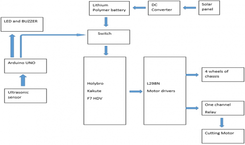
The whole system runs on the power from the Lithium polymer batteries, which are charged using the solar panel. The brain of the system is the Holybro Kakute F7 HDV. The Holybro Kakute F7 HDV controls all the operations of the autonomous device. It uses Ardupilot technology to control an autonomous device, based on the initially loaded information on a mapped-out area. When the Mission Planner software is used to do the mapping of the desired work space, the instructions are loaded onto the microcontroller. This means that the robot has a clear understanding of the mapped-out area, and can adequately carry out the strenuous task of mowing the land area, without significant human intervention.
The ultrasonic sensor is incorporated to identify possible obstacles [21]. The Ultrasonic device is connected to the Arduino UNO microcontroller to trigger the device to stop, and turn the buzzer on [22]. This is to alert the operator of an obstacle. If left unattended to after some time, the rover goes off. An overview of the developed system is represented by the block diagram shown in Figure 1.
Figure 1. Block diagram of the system
2.2 Major components used
The hardware components used are as listed below:
2.3 Design and building of robotic chassis
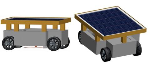
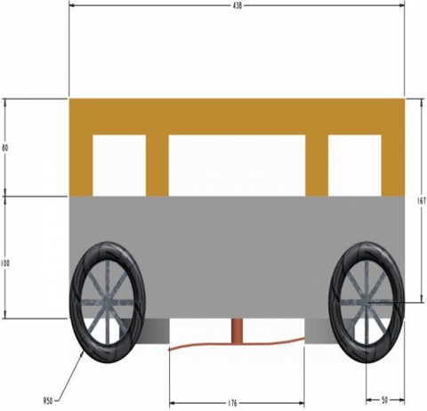
The chassis was designed using PTC Creo 9.0 parametric software while putting all necessary parameters into consideration. Figure 2 shows the isometric and side views of the CAD model. The body of the chassis was built using flat metal sheets, joined together by arc welding.
Figure 2a. 3D CAD model of robotic chassis
Figure 2b. Front view CAD model of robotic chassis
2.4 Design calculations
The force needed to drive the entire system is dependent on the specifications of the electric motors that are used to drive the wheels [9, 10]. For a system that is expected to carry a maximum weight of 8kg, high torque DC motors are required. Choosing the right DC motor is vital to achieving the all-round functionality of the system.
Power, $\mathrm{P}=I V=m g \times 2 \pi \mathrm{N} / 60$
where, $I$ = current rating of the DC motor
$V$ = Operating voltage of the electric motor
$mg$ = weight to be driven by one electric motor
$N$ = speed of the electric motor in rpm
Considering the specifications of the electric motor;
Putting these into consideration, the weight expected to be driven by one electric motor in one second is 4.14 kg. This means that the four electric motors are expected to drive a weight of 4.14 kg × 4 = 16.57 kg.
2.5 Powering the chassis
The lithium polymer batteries used has an operating voltage of 12V, and current rating of 2.2Ah.
Using the relationship;
$i \propto \frac{1}{t}$
Introducing the constant K,
$\begin{gathered}i t=k \\ I_1 T_1=I_2 T_2\end{gathered}$
The battery is rated 2.2Ah, and 3S. This means that three 3.7V batteries are arranged in series, giving a total of 11.1V. The total current output in a burst needed is produced by the 30C function. This means that thirty times the capacity of the battery is released at once. This makes 66A.
The developed Solar Powered Automated Lawn Mower functions by drawing energy from the solar source, charges its lead acid batteries and uses this to power the movement of a self-built robotic chassis and DC motor attached to a cutting blade.
3.1 Development of chassis
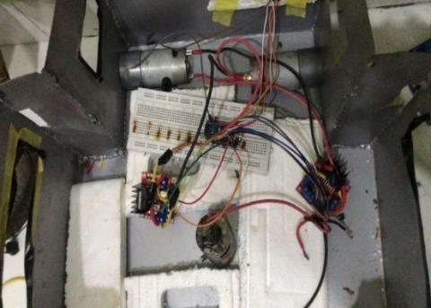
The entire frame of the chassis weighs 3.2kg, and is duly complemented by the weights of individual components of the robot. Each electric motor driving the wheels weighs 0.35kg, collectively weighing 1.4kg. The electric motor used for the cutting blade weighs 0.28kg. All other components being carried by the chassis have a collective weight of 3.6N. The entire system weighs 8.48kg by adding all the weights of the components together. This makes it movable by the electric motors, connected to the wheels.
Figure 3. Frame of the chassis with inside connections
The Chassis was developed using sheet metal, of thickness 0.8mm as shown in Figure 3. This material was chosen so as to obtain a body that is rigid in shape and can sustain the vibrations and harsh conditions outside. The material was cut out, and all the outlines were made on the sheet using a scriber. The sheet was then folded, and formed a rigid metallic structure, before further cut-outs were made to suit the design in the CAD model (Figure 2). The blade used for cutting was fabricated from aluminum plate with dimension 140mm by 22mm. The area covered by the cutting blade was calculated to be 153.95cm2. This is the area covered in one revolution of the cutting blade. The edges of the blade were sharpened to properly slice through the grasses.
3.2 Pre-mapping of workspace
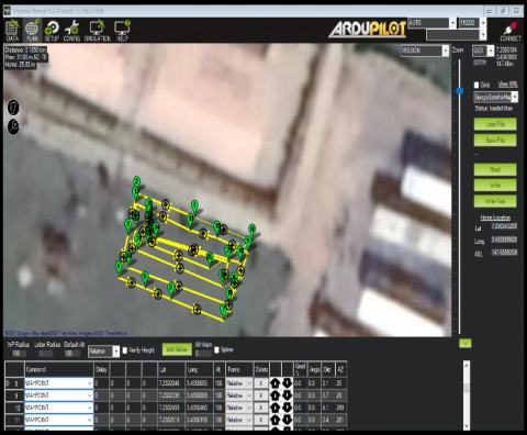
Some existing autonomous mowers use relatively complex technique including machine learning to operate. This allows the mower to recognize objects in the mowing area like flower beds, sidewalks, trees, driveways, etc., using computer vision [10]. The desired workspace was mapped with the mission planner using the home point with coordinates (7.230243°, 3.43588’). The way points represented in Figure 4 show the path through which the robot will navigate to achieve the desired output. Mission planner offers the advantage of using satellite pictures to show the work area, for better recognition by the user. The forward and backward patterns represent the waypoints and respectively each set point that the robot must reach. There are 26way points before the device can reach the central position in the mapped-out area, representing the end of the mission as depicted in Figure 4. Total distance covered was 135m. The Mission Planner provides:
Figure 4. Pre-mapping of the area using mission planner
Ardupilot technology has been used to map out the workspace needed for efficient navigation of the developed lawn mower in addition to the in-built mechanism for avoiding unplanned obstacles. The autonomous solar powered lawn mower is capable of mowing the workspace, and avoiding obstacles in addition to alarming the operator if an unplanned obstacle appears on the workspace. The developed robotic lawn mower has a clear understanding of the mapped-out area, and can adequately carry out the strenuous task of mowing the land area, without significant human intervention.
The use of the Mission Planner software to give the robot a sense of direction is one of the novel aspects of the work. After being highlighted and mapped using Google maps, it was modified to allow the mower to deliver the desired grass area to be clipped and mission directives to be chosen.
|
V |
Voltage in V |
| P | power, W |
| I | current, A |
|
N |
speed of the electric motor, rpm |
|
g |
gravitational acceleration, m.s-2 |
[1] Pandey, S., Munj, T., Panchal, K., Paralkar, R., Kumar, A. (2018). Fabrication of automatic solar lawn mower. International Journal of Innovative Research in Science, Engineering and Technology, 7: 3729-3736. https://doi.org/10.15680/IJIRSET.2018.0704077
[2] https://www.powerproequipment.com/commercial/evolution-lawn-mowers-throughout-history.
[3] www.pcmag.com/picks/the-best-lawn-mowers. Accessed February 2021.
[4] Dutta, P.P., Baruah, A., Konwar, A. (2016). A technical review of lawn mower technology. ADBU Journal of Engineering Technology, 4: 179-182.
[5] Vasile, P., Cioacă, C., Luculescu, D., Luchian, A., Pop, S. (2019). Consideration about UAV command and control. Ground Control Station. In Journal of Physics: Conference Series, 1297: 012007. https://doi.org/10.1088/1742-6596/1297/1/012007
[6] Sørensen, C.G., Bak, T., Jørgensen, R.N. (2004). Mission planner for agricultural robotics. AgEng 2004: 894-895.
[7] Dipin, A., Chandrasekhar, T.K. (2014). Solar powered vision based robotic lawn mower. International Journal of Engineering Research and Review, 2: 53-56.
[8] Waghmare, M., Mair, P., Waghmare, S., Dedhia, S. (2021). Automated lawn mower robot using IoT. International Journal of Engineering Research & Technology (IJERT), 9: 525-528. https://doi.org/10.17577/IJERTCONV9IS03106
[9] Neha, S.A., Asra, S. (2018). Automated Grass Cutter Robot Based on IoT. International Journal of Trend in Scientific Research and Development, 2(5): 334-337. https://doi.org/10.31142/ijtsrd15824
[10] Sivaguru, J., Anush, P. (2019). Infra red assisted navigation for automatic lawn mower robot. International Journal of Recent Technology and Engineering (IJRTE), 8: 2273-2275. https://doi.org/10.35940/ijrte.B1251.0982S1119
[11] Mulla, A.I., Sushanth, K.J., Mranila, P., Shaikh, M.H. (2016). Mohammed swalin, mohammed asfar, and mohammed yunus ugrani. dual mode lawn mower using sensors and GSM. International Journal of Advanced Research in Computer and Communication Engineering, 5: 556-559. https://doi.org/10.17148/IJARCCE.2016.55139
[12] Selvakumar, S., Fernandez, G., Vijayakumar, K. (2018). A fully automated lawn mower using solar panel. Journal of Advanced Research in Dynamical and Control System, 7: 977-983.
[13] Ajibola, O.O.E., Olajide, S., Osunde, D. (2021). Design and construction of automated lawn mower. Proceedings of the International MultiConference of Engineers and Computer Scientists, IMECS 2021, October 20-22, 2021, Hong Kong, pp. 1-12.
[14] Kanjanawanishkul, K. (2015). Path following with a time-convergence penalty term for a mobile robot. Walailak Journal of Science and Technology (WJST), 12(2): 141-150. https://doi.org/10.14456/WJST.2015.11
[15] Borekar, A.P., Kumbhalkar, C.R., Bhandarkar, H.M., Andhare, P.S., Murte, P.R., Nimje, S.C., Bhongade, S. (2017). Review paper on solar powered vision based lawm mower and pesticide sprayer robot. International Journal of Engineering Science and Computing, 7: 5833-5835.
[16] Keote, R.S., Kale, P., Raut, C., Samavedula, B., Khawade, R., Dumanwar, A. (2020). Solar based smart lawn mower. International Journal of Engineering and Advanced Technology (IJEAT), 9: 2190-2194. https://doi.org/10.35940/ijeat.D9065.049420
[17] Ramnani, S.M., Mekhe, B.R., Kuttamathu, A.B., Kotgire, S.S., Rajale, A.U. (2020). Unmanned automated lawn mower. International Research Journal of Engineering and Technology (IRJET), 7(6): 2473-2484.
[18] Kannan, S.A., Sreeraj, R., Ajith, G., Divya, S. (2018). Solar powered autonomous lawn mover. International Journal of Innovative Research in Electrical, Electronics, Instrumentation and Control Engineering, l(2): 255-260.
[19] Bhateja, N., Sethi, N., Jain, S., Mishra, Y. (2020). Lawn Mower–An Automated Machine. International Journal of Innovative Research in Computer Science & Technology (IJIRCST). https://doi.org/10.21276/ijircst.2020.8.6.7
[20] Patil, T., Patel, V., Sarvankar, P., Shah, K., Harbans, S., Nannade, S. (2016). Arduino controlled lawn mower. International Journal for Scientific Research & Development, 3(11): 392-394.
[21] Khemnar, V.K., Pawar, S.S., Uagale, S.S., Pagar, S.S., Navare, V.S. (2020). Solar powered automated lawn mower. International Journal of Engineering and Technology (IRJET), 7(6): 1893-1895.
[22] Alkhazraji, W.S. (2017). Multi-functional 4WD robot car chassis kit. International Journal of Engineering and Technology (IRJET), 11: 57-66. https://doi.org/10.13140/RG.2.2.16038.73288
[23] Sujendran, S., Vanitha, P. (2014). The smart lawn mower for grass trimming. International Journal of Science and Research (IJSR), 3(3): 299-303.
[24] Mohammed, I.K., Noaman, M.N. (2022). Optimal control approach for robot system using LQG technique. Journal Européen des Systèmes Automatisés, 55(5): 671-677. https://doi.org/10.18280/jesa.550513