Toto Rusianto*![]() | Saiful Huda | Sudarsono
| Saiful Huda | Sudarsono![]() | Muhammad Suyanto
| Muhammad Suyanto
© 2023 IIETA. This article is published by IIETA and is licensed under the CC BY 4.0 license (http://creativecommons.org/licenses/by/4.0/).
OPEN ACCESS
This paper presents an investigation of an axial generator for a small vertical-axis wind turbine. The performance of the axial generator design is tested by knowing the output voltage produced by varying the rotation. The generator is designed to generate three phases of electric power. And then through the wind turbine controller, three phases of alternating current are converted into direct current/DC. The Axial generator uses neodymium permanent magnets with many winding poles of 12 pieces. The coil uses 0.5 mm diameter copper enamel wire with a total of 400 turns each. A voltage of 30 Volt DC is obtained for the rotation of the axial generator at 300 rpm. For application, the generator can be used for a small vertical-axis wind turbine for stand-alone street lighting, which needs only 12 Volt of DC.
generator, axial, wind turbine, threes phase, coil, winding, street lighting
The use of renewable green energy that is environmentally friendly is still very low that can be utilised by people in Indonesia. The low utilisation is due to limited knowledge of scientific insight and a lack of socialization in the community. Countries such as Europe and America that have developed wind energy (wind energy) have proven that this energy can be cheaper than using conventional energy. Green energy is not only a way to save energy, it is also needed to build a healthy environment for human life and its ecosystem [1-3].
Indonesia has known as an archipelagic country that has a very long coastline, where the sea breeze blows all the time. By the equator, the wind speed in Indonesia is quite low compared to the equatorial area. Therefore, in realising a renewable energy generation system, the appropriate technology must be selected [4]. For this reason, this research is designed to manufacture a low-speed wind power plant. Stand-alone renewable energy-based power-generating options appear to be the ideal choice [5, 6]. This is following the specifications of a vertical wind turbine which is suitable for operating at low wind speeds [7]. The success of making low-speed generators is expected to be a solution to the advantages of vertical wind turbines. In addition, this success can be a connector of knowledge for the world of education and the Indonesian people, especially in developing clean and environmentally friendly renewable energy.
1.1 Wind turbine
The wind turbine converts the kinetic energy of the wind into mechanical energy from a rotating shaft [8]. The mechanical energy that drives the generator shaft is converted into electrical energy [9]. The torque and nominal speed are the mechanical outputs of the rotor that influence the load and speed of the generator [10]. Wind turbines use kinetic energy from wind speed causing the rotational motion to generate electrical energy. The electricity generated can be used for homes or businesses. A single stand-alone wind turbine can be used to generate electricity on a small scale power for one house [4]. The wind turbine developed is a micro-scale power plant where the energy produced is lower than 1500 watts [3, 11, 12].
Wind turbines based on the axis of the drive shaft are divided into two types, namely Vertical Axis Wind Turbine / VAWT and Horizontal Axis Wind Turbine / HAWT [13, 14]. Horizontal axis turbines have advantages over vertical axis in terms of power efficiency [3, 15]. Power efficiency is measured by the power coefficient (Cp). However, new research shows that vertical wind turbines are more suitable to be applied in areas with low wind speeds [16, 17]. Another advantage is that it does not require a wind rectifier and has better and stronger construction stability. In terms of increasing the efficiency of the power generated from a wind turbine, it is necessary to design a low-speed generator that can operate with low rotation [18, 19].
Wind turbines are classified based on the rotational speed of the turbine into two parts, namely variable speed wind turbines (VSWT) and fixed speed wind turbines (FSWT). FSWT is a wind turbine with a rotating rotor with a constant angular speed with a change in speed which is determined based on the gear ratio, number of generator poles and system frequency. FSWT has several advantages of a simple system, the use of low-cost power electronics circuits, and low maintenance, such as power inverters and power rectifiers. However, FSWT has weaknesses that the wind turbine cannot operate at varying wind speeds, so the energy produced is small and cannot achieve maximum efficiency [11, 20].
1.2 Permanent-Magnet Synchronous Generators (PMSGs)
Generators use mechanical rotational energy to spin a magnet across a coil of wire, or vice versa. An electromagnetic field is generated in the wire, which is proportional to the number of loops (N) and the change in magnetic flux [18]. The amount of electromotive force/emf is generated by generators according to Eq. (1), which is known as Faraday’s law of electromagnetic induction.
$e m f=N d \Phi / d t$ (1)
where:
Emf = Electro motion force (Volt)
N = number of loops
Φ = flux magentic (weber)
t = time (second)
dϕ/dt = changes of rotational speed
Eq. (1) shows that if a generator either changes its rotational speed (dϕ/dt) or the number of loops (N) it will change the emf. If any generator speed is desired to decrease then increasing the number of coils of wire will cancel the change in emf that comes from a change in the generator's rotational operational speed. this method It will allow the generator to run at a lower speed and be used for energy generation [21]. To increase the power of the generator, the magnetic field generated can take advantage of the special advantages offered by high-power rare earth permanent magnets [22]. The rare earth permanent magnet is a high-energy NdFeB type [23].
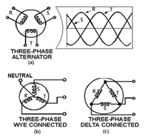
Three-phase generator has three windings spaced with a distance between one phase so that the induced voltage in one phase is 120° to the other two phases. The resulting voltage waveform in each phase is plotted on a graph, the phases at an angle of 120° with each other versus time. The three-phase generator scheme as shown in Figure 1 consists of three single-phase generators that produce a phase-out voltage of 120°. The three phases are independent of one another (RST). Generator-connected coils have two types namely WYE star-connected and delta-connected coils. Coil-connected generators in a three-phase system using star connections have been used by Latoufis et al. [24] for his research on the design and manufacturing processes for coreless axial flux permanent magnet generators [24]. Figure 1 shows the simplified schematic, view (a) shows all the windings of each phase lumped together as one winding, view (b) is WYE star-connected, and view (c) is delta-connected coils.
Figure 1. The three-phase generators connection (a) lumped connected, (b) WYE star-connected, and (c) delta-connected coils
The rotation of the rotor on the generator along the two polestek the distance between the center of the magnetic pole and the center of the magnetic pole is then measured on the circumference of the stator iron, it will cause an induced voltage in the winding. The poolstek is the distance between the middle of the magnetic pole to the middle of the magnetic pole then measured around the stator iron. The number of periods in each second is the frequency (f), then the amount of the emf is multiplied by fv, to get the effective value all must be multiplied by the comparison number. Because the number of stator windings consists of as many wire turns as many as W, the amount of emf generated on the generator is shown in Eq. (2) [21].
$E=4 . f . f v . \Phi . N$ (2)
where:
E = voltage (Volt)
f = frequency (Hz)
fv = multiple number
$\Phi$ = flux magentic (weber)
W = turns of wire
There are two types of generators based on the axis of rotation, namely axial flux generators and conventional radial flux generators. Axial flux permanent magnet machines (AFPM) have significant advantages over radial flux machines, such as high torque density, low rotor losses and high efficiency [25, 26]. AFPM machines can be classified by the placement of the magnets, the type of windings, and the number of rotors and stators. AFPM machines can be designed based on the placement of surface-type or embedded permanent magnets in the machine. The magnets in the AFPM machine can be placed on the rotor and stator. If the magnets are placed in the stator, the axial flux machine will be a type of axial flux field shifting permanent magnet machine (AFFSPM). Based on the number of rotors and stators, they are divided into three categories, namely single-sided structures, double-sided structures and multi-disk structures [18]. Pop [23] reported the results of his research using three types of constructs for wind turbine generators. in his work, he uses a permanent magnet synchronous generator (PMSG), but one has axial-flux topology (AF-PMSG), another is radial-flux outer-rotor (RFOR -PMSG), while the third is radial-flux inner-rotor (RFOR -PMSG) type. RFIRPMSG). Each of the three PMSG topologies was investigated using finite element field analysis to comparatively demonstrate the advantages and disadvantages, respectively [23]. Generator performance is tested at several operational speeds to determine the maximum power output with various speed variations. Open and short circuit tests are carried out at the desired speed of 300 rpm. With this information, the operational parameters of the generator can be obtained. The generator power output target of 60 watts is expected at 300 rpm [21].
The study reported a similar topic, but he used the finite-element (FE) simulations for analysis the axial-flux generator. The reported paper used the Finite-element (FE) simulations are performed an electromagnetic field analysis software package that supports the design and development of electric machines, actuators, circuit components etc. [23]. Dehshiri and Ketabi [18] reported, that the innovative structure of rotor teeth and the new magnet arrangement for axial-flux generator used rectangle permanent magnets with a zig-zag arrangement. This paper has experimented with making low-speed axial generators for a small vertical wind turbine. The performance of the generator design is tested by knowing the output voltage produced by varying the rotation. The prototype generator design is used as a model of a low-speed generator for a vertical-axis wind turbine. The final benefit is the creation of an energy conversion machine as a renewable energy source.
2.1 Structure and design concept
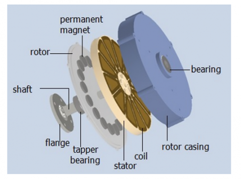
The axial generator is the direction of the magnetic field parallel to the axis of the shaft. The low-speed electric generator complies with the specifications for a vertical-axis wind turbine operating at low wind speeds. The design of the generator can be seen in Figure 2.
Figure 2. The design of the axial flux permanent magnet generator machine
The axial dimensions of the generator include the back casing rotor disc thickness, permanent magnet thickness, mechanical clearance gap, and stator thickness. After selecting a high-energy permanent magnet to determine which is suitable for this application and can be used, its thickness and quality and the actual size can be determined [24]. The construction of the axial generator as a whole has a diameter of 275 mm, a height of 75 mm, and a shaft length of 150 mm.
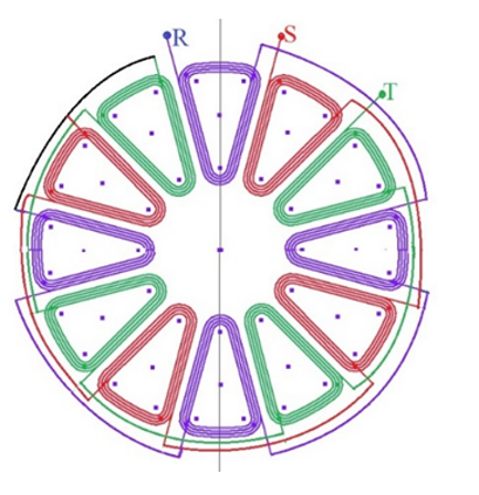
Figure 3. Schematic of copper wire winding for three-phase WYE connected
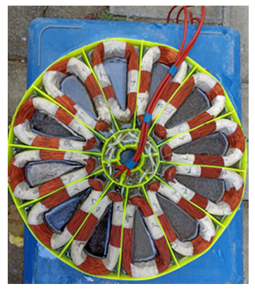
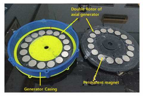
The generator is designed to produce three-phase AC (Alternating Current) using a grade N52 neodymium permanent magnet, with 16 poles. The coil/spool uses 0.5 mm diameter copper enamel wire with a total of 400 turns each coreless with a number of the twelve coils, it is shown in Figure 3. Figure 4 shows the winding copper wire of the stator topology with the WYE connection. The rotor is up and below the side, where permanent magnets are placed. Figure 5 shows the AF-PMSG has a double-rotor-one-stator topology. Rotor-PM is of Nd-Fe-B 52SH type with axial magnetization.
Figure 4. Axial generator wire winding of stator topology
Figure 5. Configuration of permanent magnet double rotor topology of axial generator
2.2 Experiment set-up
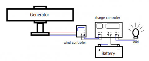
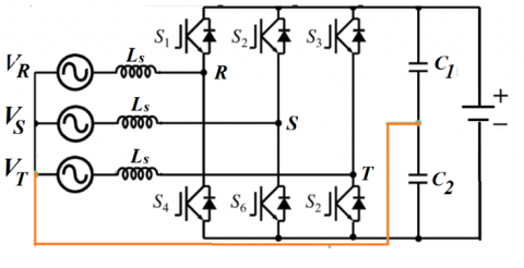
The scheme of the generator testing with the load battery and load lamp is shown in Figure 6. The various test uses the rotation of the rotor generator, voltage and electric current is measured by a Volt meter. Various speed tests with rotation according to variations in wind speed are used as kinetic energy for wind turbines that change according to weather conditions. variations in the rotational speed of the turbine by the generator are converted into electrical energy. The electrical energy by using the charge controller is stored in a battery. In dark conditions, the light will automatically turn on which is controlled by the charge controller. Figure 7 shows the three-phase bidirectional AC to DC converter topology which transfers electric power between the three-phase AC voltage supply and the DC voltage bus.
Figure 6. The scheme of generator electrical test for lighting lamps
Figure 7. Three phase three-phase bidirectional AC to DC converter
3.1 Emf generation
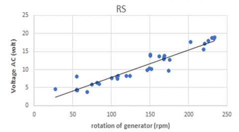
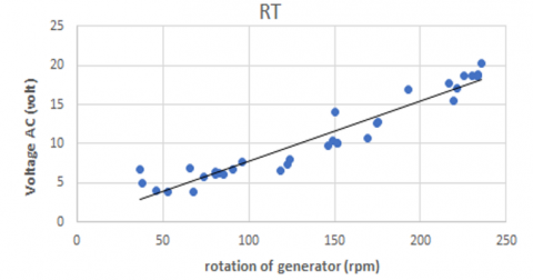
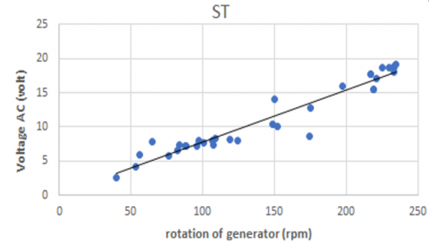
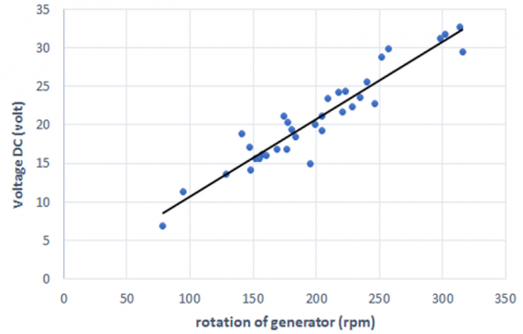
The performance of the generator design is tested by knowing the output voltage produced by varying the rotation. From the results of the manufacture, the performance test of the generator was carried out. The results of these tests are the characteristics of the three-phase generator with RST polarization as shown in Figures 8 (a), (b), (c) and (d) which measurements are carried out without load. The black lines chart in Figure 8 were generated by the trendline of the chart in the distribution of the data. The test includes measuring the three-phase RST voltage and the output DC voltage from the controller as the effect of rotation (rpm) on the voltage produced under no-load conditions.
(a) Graph of the effect of rotation (rpm) on AC voltage (V) at the output of the R-S cable
(b) Graph of the effect of rotation (rpm) on AC voltage (V) at the output of the R-T cable
(c) Graph of the effect of rotation (rpm) on AC voltage (V) at the output of the S-T cable
(d) Graph of the effect of rotation (rpm) on DC voltage (V) on the wind controller
Figure 8. The influence of rotation on the output of the wind turbine controller on DC voltage
Knowing the characteristics of the sine wave on the oscilloscope engine produced by this low rotation generator as a function of rotational speed. The measurement of the output voltage from the generator is in the form of the three-phase voltage, with the help of a control device (wind turbine controller) that converts from three-phase AC to DC. The results of the voltage measurement coming out of the generator are three-phase RST and from the controller.
3.2 Emf generation with load
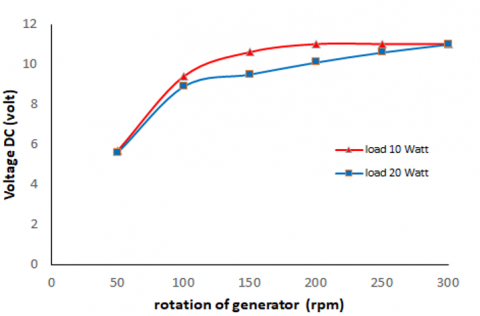
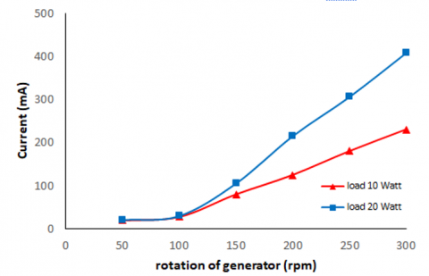
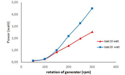
The test results of the generator are measured in the form of voltage and current at a load of 10 watts and 20 watt. In the buck converter set the voltage to 12 Volt, this is adjusted to the voltage at the load of 12 Volt. The voltage generated from the generator is highly dependent on rotation [27]. While the rotation of the wind turbine also depends on the wind speed. Testing the generator results from measuring the voltage that comes out of the axial generator from the wind controller, the measurements are carried out with a load of 10 watt and 20 watt. The results of voltage and current measurements in the presence of a load can be seen in Figures 9 (a), (b), and (c).
(a) Effect of rotation (rpm) on voltage (Volt) with a load variation of 10 watt and 20 watt
(b) Effect of rotation (rpm) on current (mA) with a load variation of 10 watt and 20 watt
(c) Effect of rotation (rpm) on out power (watt) with a load variation of 10 watt and 20 watt
Figure 9. The influence of rotation on the output of the controller in the form of DC voltage with the influence of an electrical load of 10 watt and 20 watt
The condition at 300 rpm in Figure 9 (a) shows the measurment reach the voltage of the lamp of 12 Volt DC at load10 watt and load 20 watt. If the rotation of generator was raised more then 300 rpm the voltage reach maximum at 12 Volt DC on the charge controller, but the current increase with increase the rotation of generator, it shows in Figure 9 (b). While the use of electrical equipment components such as batteries, and lights work at a constant voltage. So if the output electricity from the control device fluctuates or exceeds the component's voltage capability, it can damage the electrical system due to unstable voltage. To stabilize the voltage, efforts are being made to store electrical energy with batteries. The output of DC electric current from the wind controller is channelled to the DC controller which will continue the storage of electrical energy to the battery, and through the DC controller DC electrical energy is also channelled to the load [28]. The influence of rotation on the output voltage stable condition of the output obtained can fluctuate so that the electrical conditions are safe, and there is no voltage overload. The effect of the generator rotation on the current at each load shows that the linear curve has not yet reached the maximum condition. The effect of generator rotation on power at each load shows an increasing curve.
From the above result, it is easily concluded that the voltage output increases as turbine rpm increases. The different parameters like Voltage, Current and DC power is better than the existing system output. It is also seen that if the generator in the model is connected in series or parallel will produce more voltage. It can be easily useful for DC equipment or either to convert DC into AC rectifier systems as well as a transformer will be recommended [29]. This is by following the theory of the relationship between power and wind turbine rotation speed, the greater the rotation, the greater the power generated. The wind has kinetic energy, in a wind turbine the kinetic energy is used to turn the propeller into rotational energy. The rotational energy is transferred by a shaft leading to the generator. Rotational energy by the generator is converted to produce electrical energy. the amount of wind energy that can be converted is directly proportional to the wind speed raised to the third power, it is shown in Eq. (3) [30]
$P=\frac{1}{2} C_p \rho A v^3$ (3)
where:
P = power (watt)
Cp = coefficient power (unitless)
ρ = air density (kg/m3)
A = Area (m2)
v = wind speed (m/s)
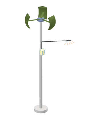
Individual small wind turbines can be used to generate electricity on a small scale [4]. As the wind turbine generators exhibited a significant difference in power generation, depending on the installation area and the wind occurrence frequency [31]. The small-scale applications of wind turbines in the long run with the development of generator technology, and the utilization of wind energy are still promising [32]. The goal of the research use this generator for used as street lighting. An illustration of street lighting with energy sources from a wind turbine can be seen in Figure 10.
Figure 10. Illustration of stand-alone street lighting by a small vertical axis wind turbine using the axial generator
The low-speed generator has been successfully manufactured, and it is shown from the results of research that at 300 rpm rotation can produce a voltage of 30 Volt DC. This voltage is large enough to charge the battery with a voltage of 12 Volt DC. This generator is suitable for use for small vertical-axis wind turbines.
The authors would like to thank The Ministry of Education, Culture, Research, and Technology, the Republic of Indonesia, Directorate General of Higher Education, Research, and Technology, Higher Education Service Institute Region V Yogyakarta in scheme Penelitian Terapan Unggulan Perguruan Tinggi (PTUPT), and The Research Institutions and Community Service in Institut Sains & Teknologi AKPRIND Yogyakarta as research-supporting institutions.
|
E |
voltage (volt) |
|
f |
frequency (Hz) |
|
fv |
multiple number |
|
W |
turns of wire |
|
P |
power (watt) |
|
Cp |
coefficient power (unitless) |
|
ρ |
air density (kg/m3) |
|
A |
Area (m2) |
|
v |
wind speed (m/s) |
[1] Afandi, A., Birowosuto, M.D., Corneliasari, K. (2022). Energy-yield assessment based on the orientations and the inclinations of the solar photovoltaic rooftop mounted in Jakarta, Indonesia. International Journal on Advanced Science, Engineering and Information Technology, 12(2): 470. http://dx.doi.org/10.18517/ijaseit.12.2.14812
[2] Nguyen, H., Nguyen, V., Ly, V., Bui, T. (2022). Biodiesel produced from pangasius oil operating a diesel engine: Case study in Vietnam. International Journal on Advanced Science, Engineering and Information Technology, 12(2): 477-482. http://dx.doi.org/10.18517/ijaseit.12.2.16159
[3] Wu, Z., Wang, H. (2012). Research on active yaw mechanism of small wind turbines. Energy Procedia, 16: 53-57. https://doi.org/10.1016/j.egypro.2012.01.010
[4] Wavhal, J., Kulkarni, R., Kulkarni, P., Gore, S. (2015). Wind power generation. International Journal of Electronics and Communications, 2(2): 31-37.
[5] Amara, M., Mazouar, A., Sayah, H. (2022). Enhanced control of wind energy conversion system based on DFIG using adaptive super twisting controllers. Journal Europeen des Systemes Automatises, 55(1): 109. https://doi.org/10.18280/jesa.550111
[6] Al-Shammari, Z.W., Azizan, M.M., Rahman, A.S.F. (2021). Grid-independent pv-wind-diesel generator hybrid renewable energy system for a medium population: A case study. Journal of Engineering Science and Technology, 16(1): 092-106.
[7] Jayaramulu, C. (2019). Modeling and analysis of a small wind turbine blade. International Journal of Science and Research, 8(4): 1188-1191.
[8] Adibowo, S., Uyun, A.S., Nur, S.M., Abdullah, K., Yandri, E., Adiatmojo, G.D. (2020). The analyse of the automotive alternator as a generator in Picohydro system: Laboratory experiment test. In Journal of Physics: Conference Series, 1469(1): 012179. https://doi.org/10.1088/1742-6596/1469/1/012179
[9] Gagnon, R., Sybille, G., Bernard, S., Paré, D., Casoria, S., Larose, C. (2005). Modeling and real-time simulation of a doubly-fed induction generator driven by a wind turbine. In Intl. Conference on Power Systems Transients, Canada.
[10] Boonsuk, T., Janon, A. (2017). Dynamic simulation of a direct-coupling 3-blade vertical-axis hydrokinetic turbine with a low speed generator. Engineering and Applied Science Research, 44(4): 249-253. https://doi.org/10.14456/easr.2017.38
[11] Syahputra, R., Robandi, I., Ashari, M. (2014). Performance analysis of wind turbine as a distributed generation unit in distribution system. International Journal of Computer Science & Information Technology (IJCSIT), 6(3): 39-56. https://doi.org/10.5121/ijcsit.2014.6303
[12] Leung, D.Y.C., Deng, Y., Leung, M.K. (2010). Design optimization of a cost-effective micro wind turbine. In WCE 2010-World Congress on Engineering 2010. International Association of Engineers.
[13] Neammanee, B., Sirisumrannukul, S., Chatratana, S. (2007). Development of a wind turbine simulator for wind generator testing. International Energy Journal, 8(1): 21-28.
[14] Chagas, C.C.M., Pereira, M.G., Rosa, L.P., da Silva, N.F., Freitas, M.A.V., Hunt, J.D. (2020). From megawatts to kilowatts: A review of small wind turbine applications, lessons from the US to Brazil. Sustainability, 12(7): 2760.
[15] Bai, C.J., Hsiao, F.B., Li, M.H., Huang, G.Y., Chen, Y.J. (2013). Design of 10 kW horizontal-axis wind turbine (HAWT) blade and aerodynamic investigation using numerical simulation. Procedia Engineering, 67: 279-287. https://doi.org/10.1016/j.proeng.2013.12.027
[16] Casini, M. (2016). Small vertical axis wind turbines for energy efficiency of buildings. Journal of Clean Energy Technologies, 4(1): 56-65. https://doi.org/10.7763/JOCET.2016.V4.254
[17] Grauers, A. (1996). Design of direct-driven permanent-magnet generators for wind turbines. Chalmers Tekniska Hogskola (Sweden).
[18] Dehshiri, M., Ketabi, A. (2022). A coreless axial flux‐switching generator for micro‐wind turbine application. Energy Science & Engineering. https://doi.org/10.1002/ese3.1309
[19] Irasari, P. (2012). Experiment and analysis of car alternator for wind turbine application. Journal of Mechatronics, Electrical Power, and Vehicular Technology, 2(1): 1-10. https://doi.org/10.14203/j.mev.2011.v2.1-10
[20] Syahputra, R., Purwanto, K., Soesanti, I. (2022). Performance investigation of standalone wind power system equipped with sinusoidal PWM power inverter for household consumer in rural areas of Indonesia. Energy Reports, 8: 4553-4569. https://doi.org/10.1016/j.egyr.2022.03.145
[21] Merrick, S. (2013). Low Speed Alternator Design. Electrical Engineering Department California Polytechnic State University, San Luis Obispo, 2013.
[22] El-Hasan, T.S. (2018). Development of Automotive Permanent Magnet Alternator with Fully Controlled AC/DC Converter. Energies, 11(2): 274. https://doi.org/10.3390/en11020274
[23] Pop, A.A., Jurca, F., Oprea, C., Chirca, M., Breban, S., Radulescu, M.M. (2013). Axial-flux vs. radial-flux permanent-magnet synchronous generators for micro-wind turbine application. In 2013 15th European Conference on Power Electronics and Applications (EPE), Lille, France, pp. 1-10. https://doi.org/10.1109/EPE.2013.6634639
[24] Latoufis, K.C., Messinis, G.M., Kotsampopoulos, P.C., Hatziargyriou, N.D. (2012). Axial flux permanent magnet generator design for low cost manufacturing of small wind turbines. Wind engineering, 36(4): 411-431. https://doi.org/10.1260/0309-524X.36.4.411
[25] Ahmed, D., Ahmad, A. (2013). An optimal design of coreless direct-drive axial flux permanent magnet generator for wind turbine. In Journal of Physics: Conference Series, 439(1): 012039. https://doi.org/10.1088/1742-6596/439/1/012039.
[26] Bouziane, Y.S., Henini, N., Tlemçani, A. (2022). Energy Management of a Hybrid Generation System Based on Wind Turbine Coupled with a Battery/Supercapacitor. Journal Européen des Systèmes Automatisés, 55(5): 623-631. https://doi.org/10.18280/jesa.550507
[27] Klach, M., Aloui, H., Neji, R., Gabsi, M., Lecrivain, M. (2017). Embedded simple excited automotive alternator modeling using magnetic equivalent circuits. International Journal of Electrical and Computer Engineering, 7(3): 1145. https://doi.org/10.11591/ijece.v7i3.pp1145-1153
[28] Patel, R., Kurre, M. (2020). Modelling and control of hybrid microgrid based on renewable energy ( PV and Wind Turbine ) by using battery management system with help of fuzzy logic and PWM Inverter. International Journal of Science and Research, 9(3): 2018-2021. https://doi.org/10.21275/SR20313212349
[29] Bhadang, S.J., Kale, B.N. (2023). Design, analysis & power generation through vertical axis wind turbine. Indian Streams Research Journal, 5(9): 1-17.
[30] Zhang, J.Z., Moreau, L., Houari, A., Machmoum, M. (2016). Design optimization and control of a double stator permanent magnet generator for tidal energy applications. European Journal of Electrical Engineering, 18(5-6): 339-359. https://doi.org/10.3166/ejee.18.339-359
[31] Kim, D., Park, B., Jang, J. (2018). Wind turbine generator efficiency based on powertrain combination and annual power generation prediction. Applied Sciences, 8(6): 858. https://doi.org/10.3390/app8060858
[32] Salami, A.A., Ajavon, A.S.A., Kodjo, M.K., Bedja, K.S. (2016). Evaluation of wind potential for an optimum choice of wind turbine generator on the Sites of Lomé, Accra, and Cotonou located in the Gulf of Guinea. International Journal of Renewable Energy Development, 5(3): 211-223. https://doi.org/10.14710/IJRED.5.3.211-223