Ouf Abdulrahman Shams*![]() | Muna Hameed Alturaihi
| Muna Hameed Alturaihi![]() | Mustafa Abdul Salam Mustafa
| Mustafa Abdul Salam Mustafa![]() | Hasan Shakir Majdi
| Hasan Shakir Majdi![]()
© 2023 IIETA. This article is published by IIETA and is licensed under the CC BY 4.0 license (http://creativecommons.org/licenses/by/4.0/).
OPEN ACCESS
This paper describes a system and technique for controlling the attitude and direction of a quadrotor vertical take-off and landing unmanned aerial vehicle (VTOL UAV) using a horizontal thrust system (horizontal thruster), and hereby we call the system “Thruster Quad-rotor”. The thruster quad-rotor operates by adjusting the rotational speed of each rotor's propellers to hold the quad-rotor’s attitude (angular orientation and linear position in flight), while simultaneously control all direction horizontal motions in the horizontal plane using four thrusters installed on each arm of the quad-rotor. Each rotor is attached to an arm “tube”. At the arm, on the tip, there is a thruster (electric duct fan - EDF). The four arms of the quad rotor are connected to the central body and aligned symmetrically at 45-degree angles to the X and Y axes forming a quad-rotor with “X” configuration. The horizontal thrusters enhance the effectiveness of the quad-rotor with novel design modifications; specifically, the horizontal thrusters increase the typical under-actuation to conventional quad-rotors. The application of the novel thruster concept leads to an increase in maneuvering of the UAV and an ability to resist winds and fly in tight spaces and scenarios, which presents flight’s mission limitations. This paper will include the practicality of this new system, its conceptual and design aspects, and the mathematical modeling of the channels for the new UAV's enhanced control and guidance system.
quad-rotor drone, thruster, EDF, under-actuation and mathematical model
The Unmanned Aerial System (UAS) industry is highly technical and serves as a barometer indicating a state's development level. UAS is a promising and dynamic industry, which has requirements for the development of national infrastructure construction, vocational aviation education institutions, high-tech industries and high-skilled talents in the industrial field. UAS are a promising and dynamic industry. UAS are in demand and has a wide range of applications in military, security and civilian fields. UAS markets are very promising, and businesses involved can reach breakeven in reasonable periods [1].
Multi-Rotor Drones are unmanned aerial vehicles (UAVs) that are raised and driven by two or more motors, often electric, equipped with propellers. The multi-copter (as it is sometimes known) is a rotary unmanned aerial vehicle (UAV), which, in contrast to fixed-wing UAVs, flies using many rotating profiles or propellers. This vehicle has a straightforward design, with control provided by adjusting the spinning of its rotors. Due to the multirotor adaptability, its perceived utility has been improved in recent years. It is capable of meeting a large number of the criteria for Vertical Take-Off and Landing (VTOL) unmanned aerial vehicles (UAVs) used in reconnaissance, surveillance and security applications [2].
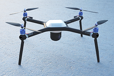
Helicopters are one of the most sophisticated flying machines available. Its intricacy is a result of its adaptability and agility for a variety of activities. The conventional helicopter consists of a main rotor and a tail rotor. There are, however, other types of helicopters, including twin rotor (or tandem) helicopters and co-axial rotor helicopters. We are mainly interested in managing a multi-rotor mini-rotorcraft in this research. The vehicle, similar to the one seen in Figure 1.
Figure 1. The 4 rotors craft (Quad-rotor)
The vehicle provides a number of benefits over standard helicopters. Because the front and rear motors spin in the opposite direction as the other two, gyroscopic effects and aerodynamic torques tend to balance out in trimmed flight.
This multirotor has no swashplate. In fact, it doesn't require any blade pitch control. The sum of the thrusts produced by each motor is the collective input, often known as the throttle input. Pitch movement is achieved by increasing (decreasing) the speed of the front motor while lowering (increasing) the speed of the rear motor. In a similar manner, lateral motors are used to move the roll. By raising (reducing) the speed of the front and rear motors while decreasing (increasing) the speed of the lateral motors, the yaw movement is produced. While doing this, the overall thrust should remain consistent.
In spite of simple multi-rotor control, the drone suffers from under-actuation, which is: multi-rotors in general and the quad-rotor in particular have problems with their under-actuation and independence. The problem of under-actuation is related to the fact that the quad-rotor has six degrees of freedom, but only four actuations (in other words, lift from the only four variable rotors due to their variable RPM). This shortage is dealt with by increasing the actuations by adding electro-mechanical controls.
The shape and configuration of VTOL UAVs must be changed for the various sites that call for reconnaissance, surveillance, and monitoring in order to ensure operations in a variety of unusual situations. Such as tight spaces between buildings, dense forests, strong winds, and locations of vital infrastructure with risky and difficult access. Multirotor electromechanical design advancements that are effective may increase the under-actuation of traditional multirotors, enhancing their agility, wind resistance, and ability to fly in restricted spaces.
UAS small size, remote or automatic control, low energy consumption, high safety in emergency situations, as well as the ability to use electric and alternative power sources, are characteristic.
In the last few decades, small-scale UAVs have become common in many applications. Since the ends of 20th century, with the development of micro electromechanical system (MEMS) technology, the multi-rotor vehicle, especially the quad-rotor vehicle, have been widely studied. The need for a more maneuverable and hovering UAV has fueled the present surge in quad-rotor development. Quad-rotors are very easy to construct, but extremely dependable and nimble, due to the four-rotor configuration. By making advancements in multi-craft communication, environment investigation, and maneuverability, cutting-edge research is extending the viability of quadrotors. If all of these advancements are combined, quad-rotor aircraft will be capable of performing sophisticated autonomous tasks that are presently impossible.
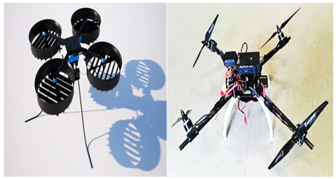
Figure 2. Flap thrust vectoring (left) Servo rotor tilting (right)
The multi-rotor VTOL UAV is a vehicle with many lifting rotors. Multi-rotors are often equipped with fixed-pitch propellers; control is achieved by varying the revolutions per minute (RPM) of each rotor. A quad-rotor is a multi-rotor with four rotors. A typical quad-rotor is electronically controlled; there are also novel types that use additional means of control and these are referred to as electromechanically controlled quads in multi-rotor dynamics and stability. Such as tilting rotors, flap vector thrust, Figure 2 and adding novel concept such as thrusters, which consider how these concepts can be used to improve the quad-rotor’s performance.
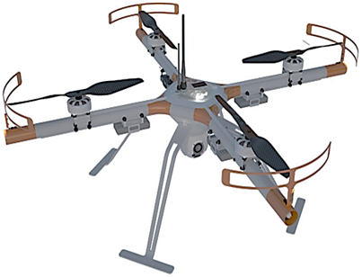
The “Thruster Quad-rotor” Figure 3 techniques will be the focus of this paper. In which we will analyses thruster’s novel concepts from two points of view. First, is the multi-rotor concept design (vehicle airframe) and second the mathematical model of Thruster Quad-rotor drone for analyzing its control and guidance systems channels [3].
Figure 3. Thruster Quad-rotor
In this paper, explore is conducted about: Enhancement of drones' control and guidance systems channels. For proving the concept, a symmetrical electric quad-rotor in (X) shape will be selected. To add thruster system, the airframe’s “Boom” is combined as air ducts for the EDFs and both of them will work (participate) to airframe structure.
So in this case, adding the thrusters in quad-rotor’s horizontal plane will plus the actuation in (X.Y) Axis’s directions (more extra two actuations). Which will lead to equalize the vehicle degree of freedom, in other words will enhance drone performance in very specific flight envelop.
A mathematical model is a mathematical representation of a system that uses mathematical ideas and equations to describe it. Mathematical modeling is the process of building a mathematical model. They come in a variety of shapes and sizes, including dynamical systems and differential equations. Typically, mathematical models are made up of connections and variables. Operators such as algebraic operators, functions, and differential operators may be used to define relationships.
Analysis of quad-rotor flight requires an elaborate mathematical model. The model must accurately represent the quad-behavior rotors throughout various flying stages (climb, descent, forward flight, maneuvers, and so on). The mathematical model integrates the dynamics of body motion and the aerodynamics of the propulsion system. The aerodynamics modeling responsibilities for propulsion systems include the following: momentum theory, blade element theory, ground effect, vortex ring state, and windmill break state. Also, to know the quad-rotor forces and torques, reference systems, Euler angles and angular speeds and Euler-Lagrange equations.
For the purpose of educate verification, the analysis, design and writing of the quad-rotor mathematical model (the equations of motion). Should be carried out on the various phases of the quad-rotor’s flights with the regards of environmental conditions.
On the subject of quad-rotor with thrusters' control, it is necessary to address mathematical modelling and simulation, due to their importance in design, creation and development of any prototype. Modelling and simulation must be carried out in a certain sequence, as this is important in the design process and the quality of the final product. Appropriate quad-rotor mathematical modelling consists of two parts. First, the design of the quad-rotor controller and, second, to create the simulation model. Development of the controller and simulation are carried out by running the model through software such as MATLAB or SIMULINK with data from real flight tests on an actual flyable prototype.
Quad-rotor with thrust vectoring is a novel concept of multi-rotor UAV control. Typical quad-rotors are limited in their mobility and flight abilities because of their basically under-actuation. The design motivation is to have a fully functional quad-rotor without inclination of the body frame for those flight conditions that require a horizontal body frame and no stressed motor operation. Such as when the quad-rotor is confronting the wind horizontally; when minimum resistance is the objective.
Developing this novel design, the goal is to transfer quad-rotors from pure flying vehicles to complete robots with independent control over all six degrees of freedom of the main body and the ability to apply forces in any directions.
A quad-rotor regarded for conception as base design for multi-rotors VTOL UAV Unlike the majority of helicopters. Quad-rotors use two identical sets of typically fixed-pitch propellers (2 clockwise and 2 counter clockwise). Propellers regulate lift and torques by varying the RPM, which are generated aerodynamically due to prop’s blades rotation. Control of vehicle motion is achieved by altering the rotation rate of two or more rotor discs, thereby changing its thrust/lift and torque load characteristics [2].
Multi-rotors in general and the quad-rotor in particular have problems with their under-actuation and autonomy. The problem of under-actuation is related to the fact that the quad-rotor has six degrees of freedom in flight. But only four actuations (in other words, lift from the four variable rotors due to their variable RPM). This shortage is dealt with by increasing the actuations by adding electro-mechanical controls.
Adding electro-mechanical concepts to a multi-rotor has many advantages:
•The quad-rotor becomes a fully controllable system capable of following any arbitrary trajectory, hovering with a predetermined pitch and roll angle, as well as motion in the appropriate orientation;
•Navigation around obstacles in a cluttered environment is possible;
•Maneuvering in only the horizontal plane is possible, useful for obstacle avoidance, see Figure 4.
•Multi-rotor input coupling can be achieved.
•The advantages of a 45° control method due to simultaneous cross-coupling control of longitudinal, lateral in horizontal to all directions quad-rotor’s movements can be demonstrated.
For a quad-rotor to hover in the wind or move opposite to the wind’s direction, it is necessary to equal or overcome the drag forces. This happens by tilting the quad-rotor’s body into the downwind direction. Logically, the higher the wind speed the higher the quad-rotor tilting required; the tilting will keep increasing until the saturation of two motors opposite the wind direction is reached (they reach their maximum RPM). Therefore, the adding of electromechanical control will have a practical actuality. There are many approaches to enhance electromechanical control such as: Flap thrust-vectoring or Servo rotor tilting control, see Figure 2. Alternatively, drone’s control enhancement by creating “Thruster Quad-rotor” system, which will be the focus of this paper, see Figure 3.
Figure 4. Quad-rotor with electro-mechanical control concepts at obstacle avoidance
The objective of this paper is to highlight novel concepts in multi-rotor dynamics and stability. It looks at a particular well-developed quad-rotor, which has been modified with specific adding a novel horizontal thrust system (horizontal thrusters) control to enhance its flying performance. The paper will give:
•A full technical description of the suggested modified quad-rotor “Thruster Quad-rotor” from full aspect concept design point of view.
•A total mathematical model of the Thruster quad-rotor, deriving kinetics and dynamic concerning the addition of the vehicle under-actuation by thrusters.
•Due to the mathematical model have multi-loop arrangement, so the control loops are related to each part of the control system and the state-of-the-art mixing mechanism for thrusters. Which mean that the suggested concept is a thrust-vectoring quad-rotor).
The Contributions of this paper are: approaches of full creation and concept design of novel “Thruster Quad-rotor”, with specifically related to airframe design with EDFs. Introduce capabilities of vehicle’s performance and simulation verification by educate representation of full aspect mathematical model based on quad-rotor’s all states equations of motion.
The Conceptual Design Process When designing a new multi-rotor, the first stage is to establish the project's goals. Design objectives might be mission requirements, performance objectives, or cost objectives. Payload, endurance, range, speed, and physical size may all constitute mission requirements. While performance requirements are often identical to mission requirements, there may be additional needs that are not mandated by the mission (which will be discussed in this article as performance/mission requirements).
Multi-copter is also called multi-rotor. It is a kind of helicopter with two or more propellers. Additionally, it is capable of VTOL. The quadcopter is the most common multicopper; a quadcopter has four control inputs, which correspond to the four propeller angular speeds [4].
The composition of multi-copter systems is both simple and complex. Compositions should be straightforward, since a multi-rotor system typically comprises of a number of highly modular components, including an airframe, a propulsion system, and a command-and-control system (Figure 5).
Figure 5. Basic composition of a multi-copter system (ESC - electronic speed controller, RC- radio control)
4.1 Thruster quad-rotor design implementation
Our objective for this paper is to propose concept design of a quad-rotor drone that capable to perform specific flight envelop by adding novel design features to the basic quad-rotor airframe, which refers as thrusters. More specifically, the goal is to implement by adding EDFs in vehicle horizontal original plane located in 45-degree angle related to (X, Y) Plane. With further mathematical model creation for quad-rotor’s controller verification as the flight controller, and program this with related equation of motions to this new design [5].
Quad-copters have gained popularity in UAV research more lately. The UAV is stabilized by these vehicles using an electronic control system and electronic sensors. These quad-rotor aircraft can fly both inside and outside thanks to their compact size and quick maneuverability. Flight control is accomplished using a minimum of four control channels in electronically operated quadrotors. Typically, one channel serves as the throttle, adjusting the power to all motors evenly. This results in the drone ascending or descending. The remaining three channels (referred to as the aileron, elevator, and rudder in radio control) control the roll, pitch, and yaw axes, respectively [2, 3]. These three control inputs operate by altering the attitude of the quad-rotor (tilt or direction). The airframe, fixed-pitch propellers, and electric motors are the primary mechanical components required for construction. The motors and propellers should be evenly spaced for optimal performance and simplicity of control algorithms. Carbon fiber composites have gained popularity in recent years owing to their low weight and structural rigidity. Electrical components required to build a functional quadcopter are comparable to those required to build a contemporary radio-controlled (RC) electric helicopter. The ESC (electronic speed control) module, the on-board computer or controller board, and the batteries are all included in this. Quadcopter research has gained popularity more lately. The UAV is stabilized using an electronic control system and electronic sensors in these vehicles. These quad-rotors can fly both indoors and outdoors thanks to their compact size and fast maneuverability. But if needed to the enhancement of drones control and guidance systems channels: There is an ambitious approach by making fundamental changes to the design of the drone. Which is the installation of 4 identical thrusters coaxial with quad-rotor motors boom, which is the solution approach of this paper.
4.2 Solution approach
This technique and system are described for controlling the attitude and direction of a quad-rotor vertical takeoff and landing (VTOL) unmanned aerial vehicle (UAV) by adding a novel horizontal thrust system (horizontal thrusters); hereby we call the system “Thruster Quad-rotor”. The thruster quad-rotor operates by adjusting the rotational speed of each rotor's propellers to hold the quad-rotor’s attitude (angular orientation and linear position in flight). While simultaneously control all direction horizontal motions in the horizontal plane using 4 thrusters installed on each arm of the quad-rotor. Each rotor is attached among the arm “tube”. Inside the tube, at the tip, there is a thruster (electric duct fan - EDF), see Figure 3.
The four arms of the quad rotor are connected to the central body and aligned symmetrically at 45 degree angles to the X and Y axes forming a quad-rotor with “X” configuration.
The horizontal thrusters enhance the effectiveness of the quad-rotor with novel design modifications; specifically, the horizontal thrusters increase the under-actuation, which are typical to conventional quad-rotors.
The application of the novel thruster concept leads to an increase in maneuvering of the UAV and a resistance to wind and capacity to fly in confined places and scenarios those are present mission limitations. A controller consists of a first control loop for controlling the quadrotor's orientation by controlling the propellers' speed. Moreover, a second control loop for controlling horizontal movement by sequentially firing the thrusters on the X and Y-axes.
4.3 Background - concept
The following is an illustration of a Vertical Take-Off and Landing (VTOL) vehicle. It is particularly useful in connection with Unmanned Aerial Vehicles (UAV), more precisely quad-rotors configured in the "X" configuration, and will be detailed in that context. It is worth noting, however, that the current drone is also adaptable to other quad-rotor configurations. Unmanned aerial vehicle (UAV) is a propelled aircraft that uses aerodynamic forces to generate lift without the need for an onboard human operator. UAVs, in general, may be flown autonomously or remotely controlled, are disposable or recoverable, and can carry payloads [5].
A drone that can take off and land vertically from a stationary place on the ground is referred to as a VTOL. VTOL planes have the ability to hover and maneuver laterally while in the air. Vertical takeoff and landing are only a few of the many modes of operation that VTOL aircraft can switch between. The advantage of VTOL aircraft is that they require less area for takeoff and landing than do aircraft that use a conventional runway. However, it is well recognized that transitions between movement phases of a VTOL aircraft while airborne generate moment forces and other unwanted aerial elements that disrupt the VTOL aircraft's stability.
Numerous studies on UAV and VTOL technologies have been conducted in an effort to streamline the combined mechanical and control design, thereby lowering complexity and the risk of failure while maintaining stability. It has been discovered that having more than one rotor improves the vehicle's balance and stability when it is in motion. These vehicles have stability issues brought on by gyroscopic moment forces produced during airplane motions as well as adverse moment forces produced by the environment.
The small-scale size remotely controlled or automatically controlled UAV have lower energy consumption, higher safety in emergencies, as well as expanded resources of electric power and alternative power sources. One of the candidates for analysis is the multi-rotor VTOL UAV. A multi-rotor is a VTOL UAV with many lifting rotors, see Figures 6-12.
Multi-rotors are often equipped with fixed-pitch propellers; vehicle motion is controlled by altering each rotor's RPM (Revolutions per Minute). A quad-rotor is multi-rotor VTOL UAV with four rotors. A typical quad-rotor with such control is also called electronically controlled quad-rotor comparable with the novel types, which use additional means to control, for example in our case the use electrical ducted fan and it is called “Thruster quad-rotor”.
The multi-rotor in general, as well the quad-rotor, have problems with their under-actuation and autonomy. The problem of under-actuation is that a quad-rotor is a six degree-of-freedom flying vehicle, but has only four actuations (variable rotors lift due to their variable RPM). This shortage is treated by increasing the actuations thru adding an electric ducted fan (4 thrusters) control design approach, which increases the actuations of the quad-rotor from four to eight [3].
To achieve autonomy of the vehicle, the energy required to perform the flight is stored in batteries, which are heavy and therefore limit the autonomy of the quad-rotor. To solve this problem, a hybrid propulsion capability (vertical and horizontal force combinations) is employed. The use of thrusters added to the quad-rotor design allows such capability enhances the vehicle’s autonomy.
Small-scale unmanned aerial vehicles (UAVs) have grown in popularity over the past several decades for a variety of uses. More research tests are being conducted on the multi-rotor vehicle, particularly the quad-rotor vehicle, because of the advancement of Micro Electro Mechanical System (MEMS) technology. The need for more maneuverable and hovering UAVs has fueled the present surge in quadcopter research. Quadcopter designs are very basic because to the four-rotor configuration, but they are extremely dependable and nimble.
By advancing multi-craft communication, environment exploration, and maneuverability, cutting-edge research is extending the viability of quadcopters. If all of these evolving characteristics can be coupled, quad-copters will be capable of performing sophisticated autonomous missions not now conceivable with other vehicles.
A quad-rotor is regarded for conception as a base design for multi-rotor VTOL UAVs. Unlike the majority of helicopters, quad-rotors use two identical sets of fixed-pitch propellers; two functioning clockwise (CW) and two acting counter-clockwise (CC) (CCW). The propellers use the variation of RPM to control lift and torques, which are generated aerodynamically due to the rotation of the propellers’ blades.
Quad-rotor with an added thruster system will have the capability to move in the horizontal plane in all direction. This will ensure navigation around obstacles in a cluttered environment, maneuvering in the horizontal plane only (obstacle avoidance without inclination). In addition, hovering in the wind or move opposite the wind’s direction. The horizontal thrust system needs to equal or overcome the drag forces; in a conventional quad rotor, this is carried out by tilting the quad-rotor’s body downwind. Logically the higher the wind speed the higher the quad-rotor tilting required, and inclination will increase until the two motors opposite to the wind direction reach saturation (they reach their maximum RPM). However, horizontal thrust is the perfect solutions to hover in wind conditions or move opposite the wind’s direction [2].
In order to control the balance and stability of a VTOL UAV system without increasing its mechanical complexity, a system and approach are needed. Additionally, in order to improve flying effectiveness and efficiency while maintaining flight stability, a VTOL UAV system is required that reduces unfavorable moment force phenomena brought on by aircraft motions.
The current paper discusses a system and technique for designing quad-rotors with thrusters for use in VTOL UAVs by varying the rotational speed of propellers on each rotor. While simultaneously activating four horizontally directed thrusters in a 45-degree arrangement relative to the X-Y body axes. In the horizontal plane, the mechanism accomplishes directional flight control.
The method for flying a quad-rotor VTOL UAV fitted with electric ducted fans, known as thrusters, is discussed in the current study in one iteration. The system consists of a quad-rotor airframe with a first rotor separated from a second rotor along the front section of a vehicle and a third rotor separated from a fourth rotor along the rear section. A propeller and a brushless electric motor are both parts of each rotor. A fixed-blade propeller with a shared plane of alignment is attached to each engine. Each rotor is connected to an arm or tube that houses an EDF thruster that is angled 45 degrees away from the X and Y-axes. With this arrangement, the thruster's directional angle with respect to the X and Y axes can be adjusted. A second control loop is used to control a thrust vector or lateral maneuvering by transferring the quad-rotors' position in relation to the first and second axes. The system also includes a first control loop for controlling the propellers' rotational speed to control the vehicle's angular and linear attitudes.
Another example is a quad-rotor vertical takeoff and landing unmanned aerial vehicle (UAV) with thrusters built into its fuselage and distributed evenly among several rotors, each of which has a fixed pitch propeller and is oriented on a common plane. A group of radially projecting arms, each of which has a thruster (tube), surrounds each rotor. A controller manages each rotor's propellers' rate of rotation. The radially projecting arms are arranged in an X-Y configuration. Additionally, a controller activates the rockets simultaneously to propel the VTOL UAV and navigate in the horizontal plane.
A technique for regulating the stability and movement of a quad rotor VTOL UAV is given in another embodiment. At the multiplicity of rotors, the propellers revolve at a comparable rotational speed. Which control accordingly the vertical lift and torque of each rotor by a vertical lift loop controller; while another horizontal loop controller controls the thrusters.
The current research discusses a VTOL UAV system with a 45-degree thruster arrangement that enables increased payload capacities while keeping an appropriate component footprint.
Another element is a VTOL UAV system and technique in which management of the rotational speed of each propeller minimizes or eliminates undesirable gyroscopic moment forces. In addition, other torque forces operating on the aircraft because of thruster engagement manipulation for directional control.
Another component of the current problem is a VTOL UAV system and technique that lowers the complexity of the rotational speed controller by controlling the thrusters to steer the aircraft. The speed controller maintains the aircraft's stability, while a controller modulates the thruster control to change the aircraft's direction.
This concept makes the quad-copter a fully-controlled system which can track any arbitrary trajectory. Including hovering controlled horizontal motion, motion with a desired vehicle orientation, and navigation of the quad-rotor around obstacles in a cluttered environment (Clutter environment navigation execution around obstacles). Moreover, maneuvering in only the horizontal plane (obstacle avoidance without inclination).
For the thruster quad-rotor to hover in the wind or move opposite the wind’s direction, it is necessary to equal or overcome the drag forces. This will happen by engagement the quad-rotor’s thrusters in the proper direction and choose the right thruster according to their numbering. Logically the higher the wind speed the higher thruster thrust required; the thrust will increase until the maximum thrust is reached.
Additionally, the current disclosure aims to lessen the VTOL UAV's flight dynamic complexity. While maintaining the stability of the system, the VTOL UAV system is simple and compact and to reduce the electric system power consumption which leads to increased vehicle flight duration, see Figures 13-20.
4.4 Descriptions by the drawings
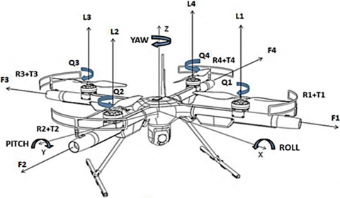
Figure 6. Quad-rotor (VTOL - UAV) with horizontal thrusters
Figure 7. Body system coordinates forces and moments acting on the quad-rotor
Figure 8. Vertical lifting system and thruster’s systems; Subsystem 1 contains four vertical rotors (electric motors with propellers); subsystem 2 contains four horizontal force resources the EDFs (electric ducted fans or thrusters)
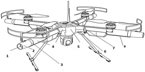
Figure 9. The major components of the thruster quad-rotor: 1. Carbon Fiber propeller protective guard; 2. Thruster at the tip of the radial arm; 3. Vertical rotor propeller; 4. Thruster at the tip of the radial arm (rear view); 5. Foldable landing gear; 6. Useful payload (camera gimbal); 7. Thruster quad-rotor airframe central piece; 8. Hinge to swivel the radial arm for vehicle transportation and packing; 9. Radial arm tubular piece between the airframe central piece and the tip thruster; 10. Brushless electric motor; 11. Bay of lithium batteries (lipos) with the motor’s electronic speed controllers (ESC); 12. Bay for electronic and communications components in the thruster quad-rotor airframe central piece; 13. Communications antennas (video, data and control)
Figure 10. The combination of the parts of the vertical power system: 1. Carbon fiber propeller protective guard; 2. Thruster quad-rotor airframe central piece; 3. Fixed-pitch propeller (carbon fiber); 4. End piece of the radial arm (the body of the thruster); 5. Radial arm tubular piece; 6. Hinge; 7. Lipos (Batteries) with ESC; 8. Brushless electric motor
Figure 11. The combination of the parts of the horizontal power system (the thruster): 1. thruster outlet; 2. thruster nozzle; 3. outer clamp to connect the thruster to the radial arm tubular piece; 4. radial arm tubular piece between the airframe central piece and the tip of the thruster; 5. central piece; 6. radial arm folding guide with holder; 7. inner clamp to connect the airframe central piece to the radial arm tubular piece; 8. thruster’s wiring cover
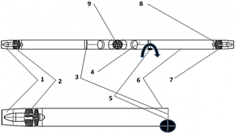
Figure 12. The detail of the thruster: 1. 2. the stator blades; 5. rotor impeller; 9. inlet tube; 3. thrust tube; 4. outlet nozzle. The thruster quad-rotor is assembled by special connection pieces: the elbow shape 6 and line tubular pieces (front and back) two pieces 7, and (left and right) two pieces 10. For vehicle convenient packing and box transportation, the airframe is equipped with a radial arm folding mechanism 8, so that it is folded vertically down with the hinge around axis o-o
Figure 13. The thruster’s system side view
The upper part of the Figure 13 is the combination of thruster 7; outer clamp to join thruster with tubular radial arm 8; radial arm 6; hinge 5 (shown for one arm 6); center piece 4; inner clamp to join center piece 4 and radial tubular arm 3; thruster’s (EDF) stator blades 2; the thrust tube with nozzle 1.
The lower part of Figure 13 illustrates a single combination of radial arm plus the thruster with the same parts numbering as per the upper drawing.
Figure 14. The parts of the thruster: 1. the inlet hub; 2. rotor with blades; 3. stator with blades; 4. electric brushless motor; 5. central outlet body; 6. thrust tube; 7. thruster air intake
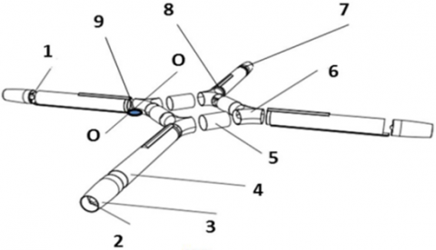
Figure 15. The thruster’s system assembly parts: 1. thruster EDF unit; 2. thruster outlet; 3. thrust tube; 4. radial boom; 5. parts of central pieces; 6. elbow parts of center pieces; 7. clamp to join the thruster with the radial boom; 8. clamp to join the radial boom with the vehicle’s airframe central pieces; 9. swiveling hinge for radial arms folding around axis o-o
Figure 16. Upper drawing is the vehicle’s booms in flying configuration; the lower part is the boom assembly in folded configuration. Also shows: 1. the radial arm; 2. folding hinges; 3. airframe central pieces; 4. thruster EDF
Figure 17. The thruster quad-rotor VTOL UAV, illustrating the thrusters’ system top view and the body axis system (X, Y, Z). Thruster numbering is in clockwise order (f5, f6, f7, f8) directions of the vehicle’s motion in the horizontal plane (as an indication the front and right direction of the thruster quad-rotor motion is shown). Opposite them is are the back and left directions (not showed)
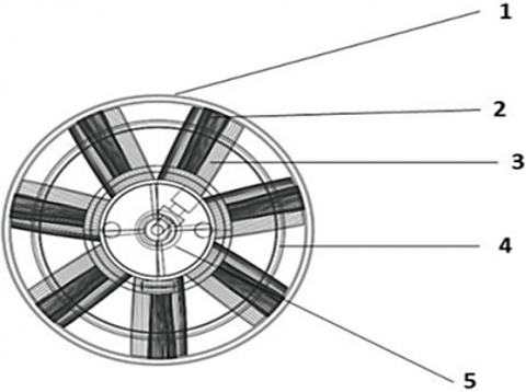
Figure 18. Front view of a thruster (Electric Ducted Fan), illustrating the thruster parts: 1. EDF air intake; 2. stator blades; 3. rotor (impeller) blade; 4. Thrust tube with nozzle; 5. Brushless electric motor
Figure 19. Top view of a thruster quad-rotor VTOL UAV, illustrating the body coordinate system, rotors forces, torques (T) and rotors/thruster numbering and thruster’s thrust directions
Figure 20. The dynamic forces arrangement (vertical and horizontal systems) for the thruster quad-rotor mathematical model derivation
The transfer of a real situation into a mathematical form is referred to as mathematical modeling. Modeling entails creating circumstances from real life or converting issues from mathematical explanations into a reality that is plausible or genuine fundamental concepts in mathematical modeling. This is the process of describing a real problem in mathematical terms, usually in the form of equations, and then using these equations to both understand the original problem and discover new features of the problem.
It is possible to forecast the location and attitude of a quad-rotor drone using a mathematical model by knowing the four angular velocities of the propellers, i.e., it permits computer modeling of quad-rotor behavior under various situations.
Related to this paper for the target of disassemble the problem: first briefly the conventional quad-rotor mathematical model will be analyzed, then introduce specific points to “Thruster Quad-rotor” [2, 7].
5.1 Quad-rotor mathematical model
The mathematical model of a quad-rotor is irreplaceable for simulating its movement and subsequent modeling of the control algorithm. Additionally, the mathematical model serves as a starting point for comprehending the mathematical concepts and physical rules that govern the quadrotor system.
The objective is to develop a mathematical model that accurately describes the behavior of a quad-rotor and can be adapted to various new multi-rotor drone configurations with minor adjustments [8].
For the mathematical modelling of novel concepts, it is essential to start with, a conventional quad-rotor and then analyses new developed thruster quad-rotors. By altering the speed and direction of rotation of the motors, the quad-rotor can change its position and orientation. There are 12 (four groups by three parameters) states that describe the quad-rotor’s dynamic behavior:
• space position: P=[x y z];
• linear velocity: V=[ux vy wz];
• rotational angles: $\Omega=\left[\begin{array}{lll}\varphi & \theta & \psi\end{array}\right]$;
• angular velocities: $\omega=[p \varphi q \theta r \psi]$.
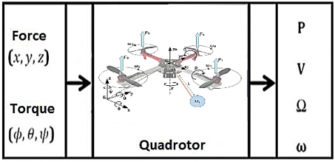
These quantities may be thought of as the quad-outputs rotor's whilst the inputs are the applied forces and torques created by the rotation of the four motors. Figure 21 illustrates the control model's inputs and outputs. This illustration depicts the quad-rotor plant as a complete mechanical system. In general, Newton's second law of motion is being used to depict the quad-motion rotors.
Figure 21. Quad-rotor mathematical model inputs and outputs
Therefore, the net force and the net moment acting on the quad-rotor are written as:
Fnet $=\mathrm{d} / \mathrm{dt}[m V]+\omega x[m V]$;
Mnet $=\mathrm{d} / \mathrm{dt}[I \omega]+\omega x[I \omega]$;
where, (m) is the quad-rotor mass and (I) is the inertia matrix.
For a quad-rotor, the lift force is distributed in four shares, one to each rotor and these forces are transmitted to the propellers (T1, T2, T3 and T4) according to the rotor/motor numbering. Figure 22 shows Quad-rotor frames, forces, torques and control.
To find the values of these forces, the blade element momentum theory is used and they are a function of the rotation speeds of the propellers (denoted ω1, ω2, ω3 and ω4, to match the motors). The relationship used is: Fi=kωi2, where i=1,2,3,4. k is a (proportionality coefficient).
Figure 22. Quad-rotor frames, forces, torques and control
The thrust values depend on the propeller shape and air density. Other values affect the quad-rotor, such as its mass (m) and weight (mg). It is natural that moments accompany propeller rotation (denoted M1, M2, M3 and M4), and their value is calculated as: Mi=L×Fi, where i=1, 2, 3, 4. L is the arm distance from the rotor axis to quad-rotor CG (center of gravity).
It is very important to know the forces and moments to define the quad-rotor modelling specifications, and to find the dynamic changes of these forces and moments is the foundation of quad-rotor dynamic mathematical modelling. Which in turn is the basis of quad-rotor design and control with possible further developments.
Therefore, quad-rotor mathematical modeling summary is:
Quad-rotor mathematical modeling
• Space position P=[x y z];
• Linear velocity V=[u v w];
• Rotational angles $\Omega=\phi \Theta \psi$;
• Angular velocities ω=ρqr.
Quad-rotor orientation representing by the rotation matrix:
$\mathbf{R}_{B \text { to } \mathcal{J}}=\left[\begin{array}{ccc}c_\psi c_\theta & c_\psi S_\theta S_\phi-s_\psi c_\phi & c_\psi S_\theta c_\phi+s_\psi S_\phi \\ s_\psi c_\theta & S_\psi S_\theta S_\phi+c_\psi c_\phi & s_\psi S_\theta c_\phi-c_\psi S_\phi \\ -s_\theta & c_\theta S_\phi & c_\theta c_\phi\end{array}\right]$
Quad-rotor control strategy illustrated on Figure 23.
Figure 23. Quad-rotor control strategy
Quad-rotor mathematical model consists of 6 dynamics equations;
-3 Linear system equations:
$\begin{gathered}m \ddot{x}=\Sigma F i(s \psi s \varphi+c \psi s \theta c \varphi)- \\ C D 1 \dot{x}=(s \psi s \varphi+c \psi s \theta c \varphi)\left(k\left(\omega 1^2+\omega 2^2+\omega 3^2+\omega 4^2\right)\right)-C D 1 \dot{x}; \\ m \ddot{y}=\Sigma F i(s \psi s \theta c-c \psi s \varphi)-C D 2 \dot{y}=(s \psi s \theta c \varphi- \\ c \psi s \varphi)\left(k\left(\omega 1^2+\omega 2^2+\omega 3^2+\omega 4^2\right)\right)-C D 2 \dot{y}; \\ m \times \ddot{Z}=\Sigma F i(c \theta c \varphi)-m g-C D 3 \dot{z}=(c \theta c \varphi)\left(k\left(\omega 1^2+\omega 2^2+\omega 3^2+\omega 4^2\right)\right)-g- \\ C D 3 \dot{z}.\end{gathered}$
where, CD1, CD2 and CD3 are drag coefficients, and (k(ω12+ω22+ω32+ω42))=u1 are the quad-rotor control inputs.
-3 Rotational system equations:
Ixx φ ̈ = l (F3 − F1 –C1DR φ̇) = l ($\dot{\Theta}$ ψ̇ (ΣIy – IZ)) + k (ω42 - ω22) – C1DR φ̇);
Iyxθ ̈ = l (F4 − F2 –C2DR$\dot{\Theta}$) = l (φ̇ψ̇ ( Iz – Ix)) + k (ω32 - ω12) – C2DR$\dot{\Theta}$);
Izxψ̈ =M1 − M2 + M3 − M4 – C3DR ψ̇ = φ̇ $\dot{\Theta}$ (Ix – Iy) +Km (ω12 – ω22 + ω32 – ω42) – C3DR ψ̇).
where l is the distance of each rotor from the vehicle’s CG. Ix, Iy and Iz are moments of inertia along each of the axes, and C1DR, C2DR and C3DR are rotational drag coefficients.
Mi, (i=1,2,3,4) that rotor moments produced via the angular velocity of the rotors also given by: Mi=Kmωi2; Km is a constant.
u2=k(ω42-ω22)
u3=k(ω32-ω12)
u4=Km(ω12-ω22+ω32-ω42)
where, u2, u3 and u4 are angular quad-rotor control inputs.
5.2 Thruster quad-rotor mathematical modeling
In this paper, part we reflect on the thruster quad-rotor’s modelling and control with regards to the specific pusher impact of the thruster on the vehicle’s forces and moments as they directly affect the quad-copter dynamics and stability.
Quad-rotor with thrust vectoring is a novel concept of multi-rotor UAV control. Typical quad-rotors are limited in their mobility and flight abilities because of their basically under-actuation. The design motivation is to have a fully functional quad-rotor without inclination of the body frame for those flight conditions that require a horizontal body frame. Moreover, no stressed motor operation, such as when the quad-rotor is confronting the wind horizontally; when minimum resistance is the objective [2].
The reason to choose a quad-rotor with thrusters, due to it is similar to a conventional quad-rotor, and equations of motion of the conventional quad-rotor are well experimented. Which can help to reveal the differences needed to manage the required performance of the investigated quad-rotor. In addition, their mathematical model helps clarify the goals and benefits when thrusters are added to the design. In common with conventional quad-rotors, the body frame consists of three main parts: central hub, carbon tubes (arms installation is at 45° relative to the (X, Y) horizontal axes) and two groups of propulsion units.
The design should also ensure the correct position of the quad-rotor’s CG (center of gravity), so that the trend line of the thruster horizontal force direction passes through the CG. This avoids the generation of longitudinal and lateral moments because of the distance between the trend line and the CG is not equal to zero. In addition, the control algorithm is designed so that all the thrusters are able to function independently from each other.
The quad-rotor prototype design has the ability to control its rotors, thus making it possible to overcome the under-actuation and behave as a fully actuated flying vehicle. Driven by these limitations, a novel concept of a quad-rotor UAV with thruster is proposed with a certain strategy of motion by operating two thrusters per each horizontal axes (X, Y). This will give full controllability of the quad-rotor pose in 3D space. Developing this novel design, the goal is to transfer quad-rotors from pure flying vehicles to flying robots with independent control over all six degrees of freedom of the main body and the ability to apply forces in any directions. Figure 24 shows “Thruster Quad-rotor” arrangement of all forces and torques for mathematical modeling.
Figure 24. Thruster Quad-rotor arrangement of all forces and torques for mathematical modeling
5.3 Thruster quad-rotor translational motion
In thruster quad-rotor the thrusters for initial analyzing, forces vectors will be at the same plane of drone CG (center of gravity) location (no vertical displacements). In other words the effect of thrusters on vehicle dynamics will be only in transitional motions or only liner equations system, which they are the target of interest. We take into account the forces that originate from three separate sources: inertia, air drag, and gravity [8] to create the dynamical model of the flying aircraft. The motions of translation and rotation are contrasted with them.
Using the Newton-Euler approach the translational subsystem can be expressed as:
$\begin{gathered}m \dot{v}=\bar{f} \\ m \ddot{\xi}=F_p+F_d+F_g\end{gathered}$
where,
$F_p$ determines the amount of force generated by the propeller mechanism,
$F_d$ is the vector of drag forces,
$F_g$ represents gravity, m is the vehicle's mass,
$\xi=[x, y, z]^T$ Is this the case with regards to $\mathcal{J}$.
The force $F_p=\left[f_x, f_y, f_z\right]^T$ expressed in the frame $\mathcal{B}$ is given by:
$F_p^{\mathcal{B}}=\left[\begin{array}{l}u_x \\ u_y \\ u_z\end{array}\right]=\left[\begin{array}{c}f_5-f_7 \\ f_6-f_8 \\ \sum_{i=1}^4 f_i\end{array}\right]$
where, the forces fi (i=1,4) are the forces generate form the propellers, f5, f6, f7 and f8, are the forces created by thrusters (EDF’s thrusts).
Then the vector $F_p$ with respect to inertial frame is obtained by: $F_p=\mathbf{R} F_p^{\mathcal{B}}$, where R is the rotation matrix representing the orientation of the rotorcraft from $\mathcal{B}$ to $\mathcal{J}$.
We use cθ to denote cosθ and sθ for sinθ
$\mathbf{R}=\left[\begin{array}{ccc}c_\psi c_\theta & c_\psi S_\theta S_\phi-s_\psi c_\phi & c_\psi S_\theta c_\phi+s_\psi S_\phi \\ S_\psi c_\theta & S_\psi S_\theta S_\phi+c_\psi c_\phi & S_\psi S_\theta c_\phi-c_\psi S_\phi \\ -S_\theta & c_\theta S_\phi & c_\theta c_\phi\end{array}\right]$
Let $F_d$ is the drag vector; as previously stated, the drag force encountered by the UAV is proportional to its translational speed. The drag vector is then defined as follows:
$F_d=K_d \dot{\eta}$ Where $K_d=\operatorname{diag}\left[k_{d x}, k_{d y}, k_{d z}\right]$ is the matrix containing the coefficients of translational drag, the gravitational force $F_g$ acts only on the z - axis, then this force is represented by: $F_g=m\left[\begin{array}{lll}0 & 0 & g\end{array}\right]^T=m g$.
We examine the control inputs u, ux, and uy in order to describe the extra forces operating on the quadrotor. We have:
$\begin{gathered}u_x=f_5-f_7=u_{x_1}-u_{x_2} \\ u_y=f_8-f_6=u_{y_1}-u_{y_2} \\ u_z=u\end{gathered}$
where ux1 and ux2 are the control inputs for the front and rear thrusters, respectively, in the x-axis. In the y-axis, uy1 and uy2 are specified identically for the left and right thrusters. While u is defined in the following manner: $u=f_1+f_2+f_3+f_4$.
The thruster’s forces (thrusts) can be predicted by calculations from EDF theory in depend on many factors, specifically its impeller shape, blade numbers and electric motor RPM. In addition, the thrusts also can be found experimentally on special test stand for EDF, they also give reasonable results. For both cases, the force vector of the translational dynamic of the thruster quad-rotor will represented as:
$F_p^{\mathcal{B}}=\left[\begin{array}{l}u_x \\ u_y \\ u_z\end{array}\right]=\left[\begin{array}{l}f_5-f_7 \\ f_6-f_8 \\ \sum_{i=1}^4 f_i\end{array}\right]$
By introducing $F_p, F_d$ and $F_g$ in $m \ddot{\xi}=F_p+F_d+F_g$, we obtain translational dynamic of the Thruster quad-rotor Drone in general form with respect of 45 degree thrusters location in horizontal plane and the u5, u6 are input vectors related to thruster thrust forces (f5, f6, f7and f8):
$\begin{gathered}m \ddot{x}=\left(F_1 s \alpha_1 c \psi c \theta-F_3 s \alpha_3 c \psi c \theta-F_4 s \alpha_4 c \psi s \theta s \varphi\right. \\ +F_4 s \alpha_4 s \psi c \varphi+F_2 \alpha_2 c \psi s \theta s \varphi-F_2 s \alpha_2 s \psi c \varphi \\ +F_1 c \alpha_1 c \psi s \theta c \varphi+F_2 c \alpha_2 c \psi s \theta c \varphi \\ +F_3 c \alpha_3 c \psi s \theta c \varphi+F_4 c \alpha_4 c \psi s \theta c \varphi+F_1 c \alpha_1 s \psi s \varphi \\ \left.+F_2 c \alpha_2 s \psi s \varphi+F_3 c \alpha_3 s \psi s \varphi+F_4 c_4 s \psi s \varphi\right) s 45^{\circ} \\ -\left(C_{D 1} \dot{x}\right) s 45^{\circ}-\left(u_5-u_6\right) \\ m \ddot{y}=\left(F_1 s \alpha_1 c \psi c \theta-F_3 s \alpha_3 s \psi c \theta-F_4 s \alpha_4 s \psi s \theta s \varphi\right. \\ +F_2 s \alpha_2 s \psi s \alpha_2 s \varphi-F_4 s \alpha_4 c \psi c \varphi+F_2 s \alpha_2 c \psi c \varphi \\ +F_1 c \alpha_1 s \psi s \theta c \varphi+F_2 c \alpha_2 s \psi s \theta c \varphi \\ +F_3 c \alpha_3 s \psi s \theta c \varphi+F_4 c 4 s \psi s \theta c \varphi-F_1 c \alpha_1 c \psi s \varphi \\ \left.-F_2 c \alpha_2 c \psi s \varphi-F_3 c \alpha_3 c \psi c \varphi-F_4 c \alpha_4 c \psi s \varphi\right) s 45^{\circ} \\ -\left(C_{D 2} \dot{y}\right) s 45^{\circ}+\left(U_5-U_6\right) \\ m \ddot{z}=\left(-F_1 s \alpha_1 s \theta+F_3 s \alpha_3 s \theta-F_4 s \alpha_4 c \theta s \varphi\right. \\ +F_2 s \alpha_2 c \theta s \varphi+F_1 c \alpha_1 c \theta c \varphi+F_2 c \alpha_2 c \theta c \varphi \\ \left.+F_3 c \alpha_3 c \theta c \varphi+F_4 c \alpha_4 c \theta c \varphi\right) s 45^0-m g-C D_3 \dot{z}\end{gathered}$
5.4 Thruster quad-rotor control system
The control of the quad-rotor with such novel design is executed by two control loops: the first controls the rotation of the motors in a manner identical to conventional quad-rotor. Stability and motion are controlled by the quad-rotor’s inclination as the motors are controlled by their RPM. The second control loop is to control the quad-rotor transition in the horizontal plane (without inclination) in all directions. The transition is executed by either control the rotors at different RPMs, or thruster’s control relative to the quad-rotor arms.
On the subject of quad-rotor combined control, it is necessary to address mathematical modelling and simulation, due to their importance in design, creation and development of any prototype. Modelling and simulation must be carried out in a certain sequence, as this is important in the design process and the quality of the final product. Appropriate quad-rotor mathematical modelling consists of two parts. First, we must design the quad-rotor controller and, second, we must create a simulation model. Development of the controller is carried out by running the model through software such as MATLAB or SIMULINK with data from real flight tests on an actual flyable prototype [8]. The control system is critical for the quad-stability, rotor's since it enables precise control of the attitude and altitude states. Its primary objective is to move the quad-rotor to a new target location (referred to as the 'reference') and to respond fast and controllably to external disturbances. Attitude control is critical for aircraft stability. The quad-rotor in space is represented through 12 state vectors, which are obtained by altering the mathematical model’s differential equations to the form:
$\dot{X}=[\ddot{\varphi} \dot{\varphi} \ddot{\theta} \dot{\theta} \ddot{\psi} \dot{\psi} \ddot{z} \dot{z} \ddot{x} \dot{x} \ddot{y} \dot{y}]=f(X, U)$
where, $X=[\varphi \dot{\varphi} \theta \dot{\theta} \psi \dot{\psi} z \dot{z} x \dot{x} y \dot{y}]^T$, X is a state vector, U is the inputs vector; and T is the state space.
Now if assume the main quad-rotor dynamic system X=f(X,U) is composed from two subsystems, the angular rotational and linear transitional. At Figure 25 noted thruster quad-rotor state vectors with input vector relationships (angular, transition subsystems) and thruster quad-rotor drone control systems channels.
Figure 25. Thruster quad-rotor state vectors with input vectors (angular, transition)
We can see that three inputs (u2,u3,u4) affect six angular subsystems (six quad-rotor’s attitude outputs: angles and angular rates). The other three inputs (u1,u5,u6) affect six linear transition subsystems (six quad-rotor’s position outputs: coordinates and their rates or velocities).
The u1 input acts on electric motors' thrust at vertical axes to change and keep altitude. The u5, u6 inputs, which control the thrusters of the quad-rotor’s angles to steer and position change in the horizontal plane. Figure 26 shows the control strategy of the thruster quad-rotor, it is the relationship between input vectors (u2,u3,u4), input vector u1 and both linear transitions vectors (u5,u6) with quad-rotors linear and rotational output parameters.
Figure 26. Thruster quad-rotor control strategy
The objective of this control approach is not only to maintain the vehicle's location along a three-dimensional trajectory, as a typical quad-rotor does, but also to maintain it in horizontal plane level hover and during route tracking. The controller receives four separate propeller speeds and thrusts from thrusters through control of EDF's motor RPM, or say parameters (u5,u6).
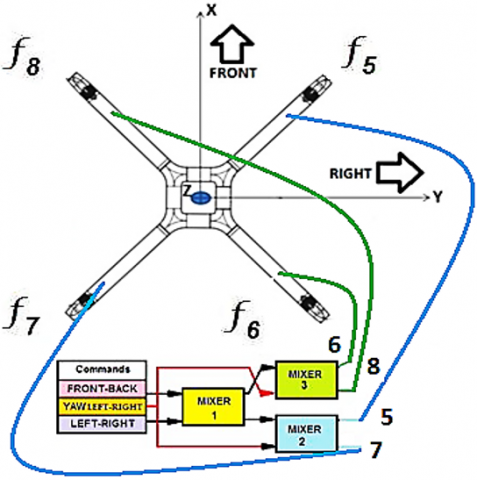
Referring to Figure 27, we can see how thrusters mix for control among the axes in the horizontal transition plane. In this case, we have three commands each one in two directions (normal and its opposite). The command could be received from a manual controller or from the drone Autopilot; for conceptual understanding, suppose that commands can be given in PWM (Pulse Width Modulation) format from minimum to maximum values or staying in the middle (neutral). The PWM commands, whatever their values, pass three mixers simultaneously (these mixers work using the same principle as the V-tail RC mixer, namely two inputs and two outputs). The connections between commands, mixers and thruster’s motors ESC are organized in such way that thruster will propel in a direction. To ensures the quad-rotor to respond in such direction in order to provide horizontal plane level transition in any direction of motion or facing the wind in the horizontal plane by rotor facing towards the wind. For example, if supposed needed to move the drone forward (front by axes X), see Figure 27. The designed control system mixers will operate thruster numbers F6 from mixer 3 and thruster number F7 from mixer 2. So that the sum of the resultant forces from both thruster’s: number F6 and F7 will move the drone to forward direction.
Figure 27. Thruster Quad-rotor with control mixing
(1) An unmanned aerial vehicle (UAV) concept was designed that includes a rotor with a propeller aligned on the same plane and a thruster on each end of a radius arm for manipulating the quad-directional rotor's angle, along that it is configured at 45 degrees from a body axis (X-Y). The vehicle's attitude is controlled by a first control loop that modifies the propellers' rotating speed and its vertical takeoff and landing trajectory is controlled by a second control loop.
(2) The mechanism that controls the vehicle's thrust vector in order to navigate horizontally along the X-Y axis.
(3) To compare different quad-rotors' thrust vectoring concepts: servo tilting rotors and flap vector thrust, with the added novel EDFs concept such as thrusters was highlighted.
(4) The system in accordance with thruster quad-rotor wherein each thruster is controlled to simultaneously thrust along the radial arm to drive the vehicle. While each propeller is regulated to revolve at a specific rotational speed to maintain the vehicle's attitude and linear velocity.
(5) An unmanned aerial vehicle with thrusters and quadrotors that can take off and land vertically includes: an aircraft body positioned in the middle of a number of rotors; and thrusters along the radial arms (tubular booms). Each rotor is equipped with a fixed pitch propeller aligned with the Z-axis. A plurality of radially protruding arms, each of which is connected to a rotor and a thruster; a controller for regulating each rotor's propeller rotational speed, as well as a controller for modulating the thrusters to steer the craft.
(6) Additionally, another component of the current design is to lower the VTOL UAV's flight dynamic complexity. While maintaining the stability of the system, the VTOL UAV system is simple and compact and to reduce the electric system power consumption which leads to increased vehicle flight duration.
(7) The thruster’s thrust force vector must pass thru the vehicle’s CG center of gravity to ensure strictly horizontal transition.
(8) The vehicle’s main controller contains two control loops; the first for vertical rotor control, and the second control loop for thruster control.
(9) The vehicle in accordance with design wherein the thruster system can enhance the vehicle capabilities in tight areas and against the wind.
(10) State-of-the-art thruster quad-rotor concept design were explained.
(11) Thruster quad-rotor mathematical modelling and their mixing methodology were presented.
(12) The prospects for future research and developments projects, such as VTOL UAV thrust vectoring was analyzed and investigated.
The authors would like to thanks Al-Mustaqbal University College, 51001 Hillah, Babylon, Iraq for the assistance in completing this work.
[1] Leishman, G.J. (2006). Principles of Helicopter Aerodynamics with CD Extra. Cambridge university press.
[2] Retha, E.A.A. (2017). Novel concepts in multi-rotor VTOL UAV dynamics and stability. Advanced UAV Aerodynamics, Flight Stability and Control: Novel Concepts, Theory and Applications, pp. 667-694. https://doi.org/10.1002/9781118928691.ch20
[3] Deshpande, A.M., Kumar, R., Minai, A.A., Kumar, M. (2020). Developmental reinforcement learning of control policy of a quadcopter UAV with thrust vectoring rotors. Dynamic Systems and Control Conference, 84287: V002T36A011. https://doi.org/10.1115/DSCC2020-3319
[4] Quan, Q. (2017). Introduction to Multicopter Design and Control (pp. 150-160). Singapore: Springer.
[5] Quadcopter Design Project. https://www.academia.edu/36369285/Quadcopter_Design_Project.
[6] Santoro, C. (2014). How does a Quadrotor fly? A journey from physics, mathematics, control systems and computer science towards a “Controllable Flying Object”. Università di Catania, Italy. 2014, https://www.slideshare.net/corradosantoro/quadcopter-31045379
[7] Musa, S. (2018). Techniques for quadcopter modeling and design: A review. Journal of unmanned system Technology, 5(3): 66-75.
[8] Ferry, N. (2017). Quadcopter plant model and control system development with matlab / simulink implementation. Kate Gleason College of Engineering Rochester Institute of Technology Rochester, New York.