Karima Benamrane* | Thameur Abdelkrim | Benlahbib Benlahbib | Noureddine Bouarroudj | Abdelhalim Borni | Abdelkader Lakhdari | Ahmed Bahri
© 2021 IIETA. This article is published by IIETA and is licensed under the CC BY 4.0 license (http://creativecommons.org/licenses/by/4.0/).
OPEN ACCESS
This paper proposes a new optimized control of photovoltaic two stages conversion cascade composed by Three Levels Boost (TLB) and Three Levels Neutral Point Clamped (TLNPC) inverter. In order to extract the maximum power from photovoltaic generator and get a balanced DC bus voltage, the duty cycles of the two TLB switches are determinate from a Fuzzy Logic Controller (FLC) for the first switch and by adding to the first duty cycle an additional duty cycle obtained by integration of the error between the two capacitors voltages of DC bus. Balancing the bus voltages by the TLB using a single regulator avoid us to use a complex balancing algorithm by the redundant vectors of TLNPC inverter. For the control of the inverter, we used a Proportional Integral (PI) regulator optimized by PSO. This command allows us to have on one side a constant DC bus voltage and a current injection in phase with the grid voltage. To have an efficient follow-up of the TLNPC inverter reference voltages, the Space Vector Pulse Width Modulation (SVPWM) is applied. The simulation is carried out in MATLAB/SIMULINK platform. The results obtained from the application of the FLC command associated with PI PSO are better compared to the simulation without optimization in terms of sum of the absolute values of the errors at the inputs of the three PI regulators.
PSO, grid connected, three-level converter, photovoltaic generator, FLC
Power electronics have experienced a very significant boom for a long time. At present, this discipline of electrical engineering affects vast and very diverse fields of application for powers covering a wide range (a few watts to several hundred megawatts). The energy conversion structures, the main players in this specialty, switch increasingly important powers.
This growing demand has been motivated by technological advances and the increase in voltage and current ratings of controlled semiconductors. However, a high power level implies either a high voltage of use or a high current of use, or even both at the same time. In all three cases, the power components used have larger ratings. Increasing the voltage is often preferred to get a better yield, and the static and dynamic performance of semiconductors often degrade under these operating conditions. In addition, despite significant progress, the evolution of the possibilities of semiconductors is slow at present compared to the demand market, in particular in terms of the voltage available. The emergence of multilevel conversion structures since the 1980s provides solutions through the serialization of power semiconductors [1, 2]. These structures ensure the distribution of the voltage stress on different switches while improving the waveforms and the harmonic spectrum of the output quantities.
The different structures can be classified into different categories such as the H-bridge serialization, serial or parallel multicellular converters or even structures using the splitting of the DC bus [3-5]. The difference between these structures or any other multilevel converter is the number of components used (switches, capacitor, dc sources). If only one voltage source is available, then inverter structure types with only one input source must be used. This type of converters has several capacitors and presents a complex control. On the other hand, if several DC sources are available, converters with several sources are used.
All of these structures have different properties and applications, although some structures have common properties. It is also possible to create new structures by mixing the different basic structures of the different families of multilevel converters or by assembling the basic structures of the static conversion.
Several conversion cascades using different types of multilevel inverters has been applied in electrical energy conversion chains. Also different DC/DC converters topologies are applied as the first stage of these cascades.
Rosmadi et al. proposed in his work a conversion chain consisting of a TLB and a five-level inverter [6]. Sahoo and Keerthipati propose a conversion cascade where it brings an improvement to the conventional three-level Z-source NPC inverter [7]. Other works apply the T structure of multilevel inverters with different DC/DC converters in the first stage such as Quasi-Switched Boost [8] and Three-Level DC-Link Type Quasi-Switched Boost [9] or Three-Level boost [10]. Ge et al. have proposed a new single-stage photovoltaic conversion chain combining the buck boost and the TLNPC inverter with two sources at the input [11]. Another work presents the use of the three levels cascaded H-bridge inverter powered by three independent photovoltaic sources via three boost converters [12].
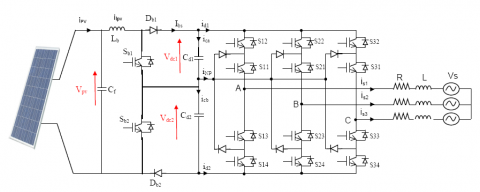
In this paper, we propose to work on the two-stage conversion cascade composed of a three-level boost fed by a photovoltaic generator and a three-level NPC inverter interconnected to the grid (Figure 1).
Different controls have been applied to the two converters of this conversion chain. Yaramasu et al. applied predictive control in a wind energy conversion chain composed by three stages: Diode rectifier, TLB and TLNPC inverter [13]. Kwon et al. [14-16] use the simple Maximum Power Point Tracking (MPPT) P&O method to TLB to extract the maximum power from the photovoltaic generator, as well as simple PI regulators to TLNPC inverter for the control of the output inverter currents. Another control method of the TLB (Golden Section Search) presented by Balakishan et al. [17] has been applied to extract the maximum power from the photovoltaic generator.
In this work, for the extraction of the maximum power from the photovoltaic generator, a FLC is introduced. This FLC output give the duty cycle to be applied to the first switch of the TLB. The duty cycle of the second switch is determined so as to have equal values of the two voltages at the output of the TLB. The TLNPC inverter control, which constitutes the second stage of the PV studied cascade, provides us the interconnection to the distribution grid. The six gains of the PI regulators used are optimized by Particle Swarm Optimization (PSO). To have an efficient follow-up of the reference voltages in the two-phase park reference, the SVPWM is applied.
Figure 1. Two-stage photovoltaic system using a three-level boost-Three-level inverter connected to the grid
2.1 Structure of the three-level boost
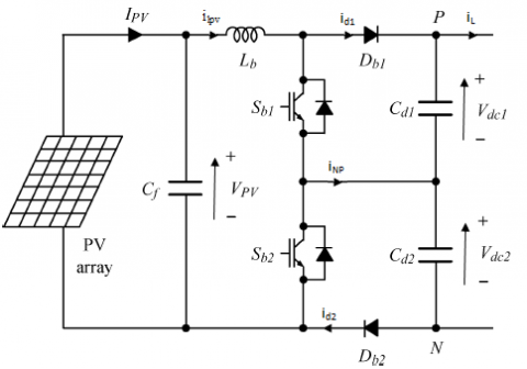
The structure of the three-level boost converter is shown in Figure 2. The converter is the combination of two boosts having the middle point of the transistors (Sb1, Sb2) and capacitors (Cd1, Cd2) connected. The controls of the transistors are shifted by Ts/2.
Figure 2. Three-level boost
The averaged model that describes the dynamic behavior of the input voltage Vpv, the inductance current ilpv and the neutral point current is given by:
$\left\{\begin{array}{l}
L_{b} \frac{d i_{l p v}}{d t}=V_{p v}-\left(1-D_{1}\right) V_{d c 1}-\left(1-D_{2}\right) V_{d c 2} \\
\quad C_{f} \frac{d V_{p v}}{d t}=i_{p v}-i_{l p v} \\
i_{N P}=\left(D_{1}-D_{2}\right) i_{l p v}
\end{array}\right.$ (1)
where:
D1: Duty cycle of switch Sb1.
D2: Duty cycle of switch Sb2.
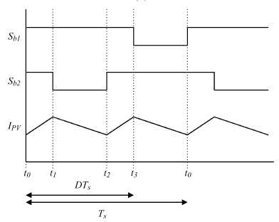
2.2 Principle of operation
The principle of operation is shown in Figure 3. When the duty cycle D (D=D1) is less than 0.5, the three-level boost converter waveforms are shown in Figure 3 (a). Before time t0, switches Sb1 and Sb2 are open. At instant t0 the switch Sb1 is closed, current flows through Lb, Sb1, Cd2 and Db2. The current of the PV generator Ipv increases (2).
$I_{p v}(t)=I_{p v}\left(t_{0}\right)+\frac{V_{p v}-{ }^{V_{d c} / 2}}{L_{b}}\left(t-t_{0}\right)$ (2)
where,
$V_{d c}=V_{d c 1}+V_{d c 2}$ (3)
At time t1, switch Sb1 is open, so both switches are open. Current flows through Lb, Db1, Cd1, Cd2 and Db2. The current of the PV generator Ipv decreases (4).
$I_{p v}(t)=I_{p v}\left(t_{1}\right)-\frac{V_{d c}-V_{p v}}{L_{b}}\left(t-t_{1}\right)$ (4)
At time t2, switch Sb2 is closed and current flows through Lb, Db1, Cd1 and Sb2. The current of the PV generator Ipv increases (2). At time t3, switch Sb2 is open, so both switches are open. Current flows through Lb, Db1, Cd1, Cd2 and Db2. The current of the PV generator Ipv decreases (4).
(a)
(b)
Figure 3. Theoretical waveforms of the three-level boost converter, (a) D<0.5, (b). D>0.5
When the duty cycle is greater than 0.5, the waveforms of the three-level boost converter are shown in Figure 3 (b). Before time t0, switch Sb1 is open and switch Sb2 is closed. At the instant t0 the switch Sb1 is closed, so the two switches are conductive. The current of the PV generator Ipv increases (5).
$I_{p v}(t)=I_{p v}\left(t_{0}\right)+\frac{V_{p v}}{L_{b}}\left(t-t_{0}\right)$ (5)
At time t1, switch Sb2 is open, current flows through Lb, Sb1, Cd2 and Db2. The current of the PV generator Ipv decreases (6).
$I_{p v}(t)=I_{p v}\left(t_{1}\right)-\frac{V_{d c} / 2-V_{p v}}{L_{b}}\left(t-t_{1}\right)$ (6)
At time t2, switch Sb2 is closed so both switches are conductive. The current of the PV generator Ipv increases (5). At time t3, switch Sb1 is open, so current flows through Lb, Db1, Cd1, and Sb2. The current of the PV generator Ipv decreases (6).
2.3 Control by Fuzzy regulator of TLB converter and balancing of DC bus
To extract the maximum power from the PV source and balance between the two capacitors voltages, previous work has proposed a double loop composed of a perturbation and observation algorithm (MPPT) associated with three PI regulators [18]. In this work, a fuzzy logic controller is introduced into the regulation loop to determine the new value of the duty cycle D1. Variations in photovoltaic power (dPpv) and voltage (dVpv) are the two inputs of FLC. The output is the variation of the duty cycle (dD) (Figure 4). For the two inputs and the output, five membership functions were used. The rules of the controller are given in the following Table 1. Mamdani's fuzzy inference and center of gravity methods are applied in this work [19].
Figure 4. Structure of the FLC for MPPT
Table 1. FLC rules
|
dP dV |
NB |
NS |
ZO |
PS |
PB |
|
PB |
NB |
NB |
ZO |
PB |
PB |
|
PS |
NB |
NS |
ZO |
PS |
PB |
|
ZO |
ZO |
ZO |
ZO |
ZO |
ZO |
|
NS |
PB |
PS |
NS |
NS |
NB |
|
NB |
PB |
PB |
NS |
NB |
NB |
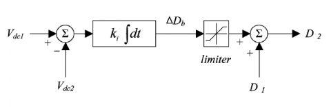
To ensure equal voltages of the two capacitors Vdc1 and Vdc2, a voltage balancing controller is essential. Figure 5 shows the three-level boost converter controller which provides equal balancing of the DC bus voltages.
Figure 5. DC Bus voltages balancing controller
The duty cycle D1 of the switch Sb1 is determined by the FLC MPPT command and the duty cycle D2 of the switch Sb2 is determined by adding to D1 an additional duty cycle ∆Db for balancing the voltages of the DC bus.
$\Delta D_{b}=k_{i} \int\left(V_{d c 1}-V_{d c 2}\right) d t$ (7)
where,
$k_{i}$ : Gain of the integrator controller.
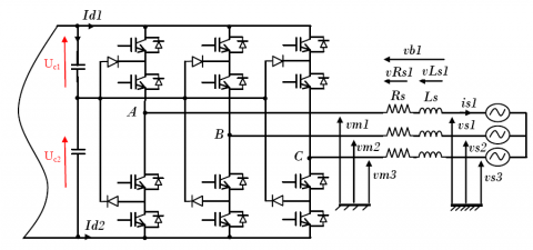
The connection between the TLNPC inverter and the grid is carried out through an RL filter (Figure 6). The purpose of this filter is to eliminate the harmonic frequencies resulting from the switching operation of the electronic converter.
Figure 6. Electrical connection of TLNPC inverter to the electrical grid
The currents transited between the converter and the grid are imposed by the coils and obtained by:
$i_{s}(t)=\frac{1}{L_{s}} \int v_{l s} d t+i_{s}\left(t_{0}\right)$ (8)
The voltages across the resistors Rs are equal to:
$v_{r s}=R_{s} i_{s}$ (9)
The voltage across the coil Ls is:
$v_{l s}=v_{b}-v_{r s}$ (10)
The application of the Kirchhoff's voltage law makes it possible to determine the voltages RL filter:
$v_{b}=v_{m}-v_{s}$ (11)
From the previous equations, we can extract the relation between the voltages of the TLNPC inverter vm, the grid vs and the intermediate filter.
$v_{m}=v_{s}=R_{s} i_{s}+L_{s} \frac{d i_{s}}{d t}$ (12)
For the determination of the reference voltages of the inverter, several methods are applied. The author [13] uses predictive strategy. Unified control mode based on decoupling control for the active and reactive powers is presented in the Ref. [18]. In this article, we apply synchronous reference frame control [20].
From Eq. (5) we can write:
$\left[\begin{array}{l}
v_{m 1} \\
v_{m 2} \\
v_{m 3}
\end{array}\right]=R_{s}\left[\begin{array}{l}
i_{s 1} \\
i_{s 2} \\
i_{s 3}
\end{array}\right]=L_{s} \frac{d}{d t}\left[\begin{array}{l}
i_{s 1} \\
i_{s 2} \\
i_{s 3}
\end{array}\right]+\left[\begin{array}{l}
v_{s 1} \\
v_{s 2} \\
v_{s 3}
\end{array}\right]$ (13)
Applying Park's transformation, the previous equation becomes:
$v_{m d}=R_{s} i_{s d}+L_{s} \frac{d i_{s d}}{d t}-L_{s} \omega i_{s q}+v_{s d}$ (14)
$v_{m q}=R_{s} i_{s q}+L_{s} \frac{d i_{s q}}{d t}-L_{s} \omega i_{s d}+v_{s q}$ (15)
Considering the following coupling voltages:
$v_{m d}=v_{b d}-e_{q}+v_{s d}$ (16)
$v_{m q}=v_{b q}-e_{d}+v_{s q}$ (17)
with:
$e_{q}=L_{s} \omega i_{s q}$ (18)
$e_{d}=L_{s} \omega i_{s d}$ (19)
The differential Eqns. (14) and (15) can be simplified:
$v_{b d}=R_{s} i_{s d}+L_{s} \frac{d i_{s d}}{d t}$ (20)
$v_{b q}=R_{s} i_{s q}+L_{s} \frac{d i_{s q}}{d t}$ (21)
By applying the Laplace transform to Eqns. (20) and (21), we obtain:
$F_{(S)}=\frac{i_{s d}(S)}{v_{b d}(S)}=\frac{1}{R_{s}+L_{s} S}$ (22)
$F_{(S)}=\frac{i_{s q}(S)}{v_{b q}(S)}=\frac{1}{R_{s}+L_{s} S}$ (23)
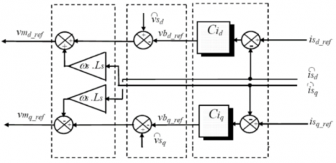
Finally, we obtain the reference voltages of the TLNPC inverter vmd_ref and vmq_ref in the park reference frame (Figure 7). These references are obtained with a control device, which combines three actions:
$v_{\text {md_ref }}=v_{\text {bd_ref }}-e_{q}+\tilde{v}_{\text {sd }}$ (24)
$v_{m q_{r e f}}=v_{b q_{r e f}}-e_{d}+\tilde{v}_{s q}$ (25)
$\tilde{v}_{s d} \quad, \tilde{v}_{s q}$ : measured values.
$e_{q}=L_{s} \omega \tilde{\imath}_{s q}$ (26)
$e_{d}=L_{s} \omega \tilde{\imath}_{s d}$ (27)
$\tilde{l}_{s q}, \tilde{l}_{s d}$: measured values.
$v_{b d_{-} r e f}=C i_{d}\left(i_{s d_{-} r e f}-\tilde{l}_{s d}\right)$ (28)
$v_{b q_{-} r e f}=C i_{q}\left(i_{s q_{-} r e f}-\tilde{l}_{s q}\right)$ (29)
Figure 7. Control device
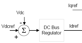
The control of the DC bus voltage (Vdc1+Vdc2) is carried out in this work by a PI regulator as presented by the Figure 8. The regulator output gives us the reference current Idref.
Figure 8. DC bus voltage control
Particle swarm optimization is characterized by a set of originally random and homogeneous individuals, which we will call particles, which move through the search space and each one constitute a potential solution. Each particle has a memory of its best visited solution as well as the ability to communicate with the particles constituting his entourage. From this information, the particle will follow, on the one hand, its desire to return to its optimal solution, and on the other hand, its mimicry in relation to the solutions found in its neighborhood. From the local and empirical optima, the set of particles will converge towards the global optimal solution of the problem treated [21].
In a D dimensional search space, the particle i of the swarm is modeled by its position vector $\overrightarrow{x_{l}}=\left(x_{i 1}, x_{i 2}, \ldots x_{i D}\right)$ and by its speed vector $\overrightarrow{v_{l}}=\left(v_{i 1}, v_{i 2}, \ldots v_{i D}\right)$ . The quality of its position is determined by the value of the objective function at that point. This particle keeps in memory the best position through which it has ever passed, which we denote by $\vec{P} \text { best }_{i}=\left(\text { pbest }_{i 1}, \text { pbest }_{i 2}, \ldots \text { pbest }_{i D}\right)$ . The best position reached by the particles of the swarm is noted:
$\vec{G} \text { best }=\left(\text { gbest }_{1}, \text { gbest }_{2}, \ldots \text { gbest }_{D}\right)$
At the start of the algorithm, the particles of the swarm are randomly/regularly initialized in the search space of the problem. Then, at each iteration, each particle moves, linearly combining the three components mentioned above. At iteration t+1, the velocity vector and the position vector are calculated from Eq. (30) and Eq. (31), respectively.
$\begin{aligned}
v_{i, j}^{t+1}=w v_{i, j}^{t}+c_{1} r_{1 i, j}^{t} &\left[\text { pbest }_{i, j}^{t}-x_{i, j}^{t}\right] \\
&+c_{2} r_{2 i, j}^{t}\left[\text { gbest }_{j}^{t}-x_{i, j}^{t}\right], j \\
& \in\{1,2, \ldots, D\}
\end{aligned}$ (30)
$x_{i, j}^{t+1}=x_{i, j}^{t}+v_{i, j}^{t+1}, j \in\{1,2, \ldots, D\}$ (31)
where, w is a constant, called the coefficient of inertia; c1 and c2 are two constants, called acceleration coefficients; r1 and r2 are two random numbers drawn uniformly in [0, 1], at each iteration t and for each dimension j.
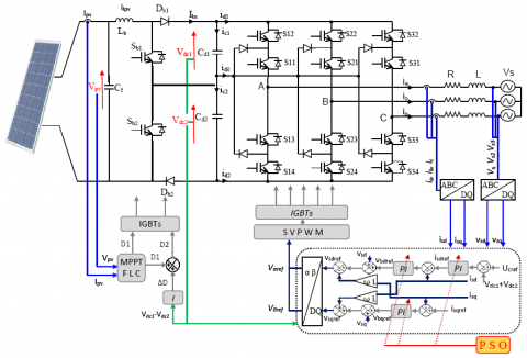
Figure 9. Two-stage photovoltaic cascade using a three-level boost-three-level inverter connected to the grid
The control diagram of the two-stage photovoltaic cascade using a three-level boost-three-level inverter connected to the grid (Figure 9) is composed by:
Simulation results are presented for the following parameters:
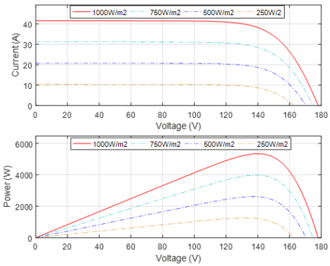
The characteristics I(V) and P(V) of the photovoltaic generator are presented in Figure 10. The maximum power point that the photovoltaic generator can generate under standard conditions is: Pmpp=5343W.
Figure 10. I (V) and P (V) characteristics of the photovoltaic generator
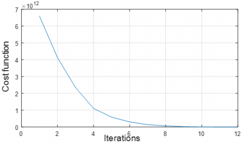
Now, we will test the performance of PI controllers optimized by PSO. The optimization process is carried out under variable climatic conditions (variable radiation). When solving the optimization problem, the number of particles and the maximum number of iterations are respectively fixed to fifteen and twelve. Figure 11 shows the evolution of the cost function. We can notice that there is a convergence towards an optimal solution after the 9th iteration.
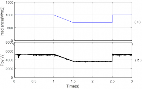
The solar radiation profile varies at t=1S from a value of Irra=1000W/m2 to 700W/m2 then returns to 1000 W/m2 as shown in Figure 12.a. The temperature is fixed at T=25℃. Figures 12.b present the power Ppv (W) of the photovoltaic generator. The three-level boost converter is controlled in MPPT in order to extract the maximum power from the photovoltaic generator. The power of this latter decreases then increases following the variation of solar radiation.
Figure 11. Cost function
Figure 12. (a) Solar radiation profile, (b) power Ppv (W)
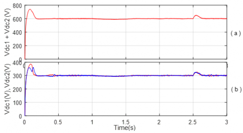
Figure 13 shows the output voltages of the three-level boost converter. Their sum is equal to the reference value Vdcref=600V imposed by the voltage control loop of inverter. The input voltages Vdc1 and Vdc2 of the three-level inverter are equal after the application of the integrator regulator to the three-level boost.
Figure 13. DC bus voltages Vdc1 (V), Vdc2 (V)
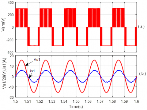
Figure 14.a shows the output voltage of the first inverter leg Vamcontrolled with SVPWM. This voltage has the three voltage levels Vdc1, 0, -Vdc2. The voltage and current of the grid of the first phase are shown in Figure 14.b. As shown in the figure, the reactive power is zero.
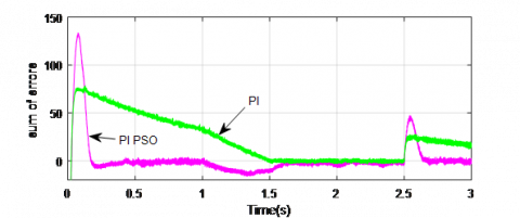
To verify the efficiency of the introduction of the PSO to our conversion cascade, we compared the sum of the absolute values of the errors at the inputs of the three PI regulators in the two simulation cases (with and without optimization) (Figure 15). From Eqns. (32), (33), the sum of the absolute values of the errors in the case of PSO optimization is twice less than the result obtained without optimization.
$\sum\left|e_{P I}\right|=7.5975 * 10^{6}$ (32)
$\sum\left|e_{P I_{P S O}}\right|=2.9707 * 10^{6}$ (33)
Figure 14. (a) Voltage of the first inverter leg, (b) Grid voltage and the phase current injected
Figure 15. Sum of absolute values of errors PI, PI PSO
In this paper a two stages photovoltaic conversion cascade composed by TLB - TLNPC inverter was presented. The proposed conversion chain is able to extract the maximum power from photovoltaic generator and equilibrate the DC bus voltages. The application of two duty cycle to the switches of TLB allowed us to balance the voltages of DC bus. In comparison with the use of conventional boost, we avoided to apply the SVPWM with redundant vectors algorithm to TLNPC inverter. The results obtained from the application of the FLC command associated with PI PSO are better compared to the simulation without optimization in terms of sum of the absolute values of the errors at the inputs of the three PI regulators. The results also show that the current injected into the grid is in phase with its voltage with also a constant DC bus voltage and follows its reference.
We propose in future works the experimental validation of the proposed control method using FPGA, DSP or Dspace platform. To improve this work, we propose as perspectives the application of other optimization methods, as well as, the optimization of not only the gains of the PI regulators, but also the membership functions of the FLC.
This project was financially supported by the Directorate General for Scientific Research and Technological Development - Algerian Ministry of Higher Education and Scientific Research.
[1] Nabae, A., Takahashi, I., Akagi, H. (1981). A new neutral-point-clamped PWM inverter. IEEE Transactions on Industry Applications, 5: 518-523. https://doi.org/10.1109/TIA.1981.4503992
[2] Lai, J.S., Peng, F.Z. (1996). Multilevel converters-a new breed of power converters. IEEE Transactions on Industry Applications, 32(3): 509-517. https://doi.org/10.1109/28.502161
[3] Benamrane, K., Abdelkrim, T., Borni, A., Benslimane, T., Abdelkhalek, O. (2016). Stability study of output voltages of stand alone single stage NPC seven levels inverter for PV system in South Algeria. In 2016 8th International Conference on Modelling, Identification and Control (ICMIC), pp. 654-659. https://doi.org/10.1109/ICMIC.2016.7804193
[4] Kunamneni, R., Ramavathu, S.N. (2019). A grid connected modular multilevel converter for photovoltaic energy conversion. Mathematical Modelling of Engineering Problems, 6(4): 535-540. https://doi.org/10.18280/mmep.060408
[5] Benamrane, K., Benslimane, T., Abdelkhalek, O., Abdelkrim, T., Borni, A. (2017). Performance evaluation and comparison of two cascaded configurations of PV generators-five levels inverter for a stand-alone application in South Algeria. International Journal of Power Electronics and Drive Systems, 8(2): 907-916. https://doi.org/10.11591/ijpeds.v8i2.pp907-916
[6] Abdullah, R., Rahim, N.A., Raihan, S.R.S., Ahmad, A.Z. (2014). Five-level diode-clamped inverter with three-level boost converter. IEEE Transactions on Industrial Electronics, 61(10): 5155-5163. https://doi.org/10.1109/TIE.2013.2297315
[7] Sahoo, M., Keerthipati, S. (2016). A three-level LC-switching-based voltage boost NPC inverter. IEEE Transactions on Industrial Electronics, 64(4): 2876-2883. https://doi.org/10.1109/TIE.2016.2636120
[8] Do, D.T., Nguyen, M.K. (2018). Three-level quasi-switched boost T-type inverter: analysis, PWM control, and verification. IEEE Transactions on Industrial Electronics, 65(10): 8320-8329. https://doi.org/10.1109/TIE.2018.2795564
[9] Tran, V.T., Do, D.T., Do, V.D., Nguyen, M.K. (2020). A three-level dc-link quasi-switch boost t-type inverter with voltage stress reduction. Energies, 13(14): 3727. https://doi.org/10.3390/en13143727
[10] Zhang, Z., Zhou, H. (2019). High performance of three-level T-type grid-connected photovoltaic inverter system with three-level boost maximum power point tracking converter. Advances in Mechanical Engineering, 11(4). https://doi.org/10.1177/1687814019843369
[11] Ge, X., Chen, M., Shi, M., Zhou, Q., Li, J., Huang, D., Yuan, Y. (2019). A single-stage buck-boost three-level neutral-point-clamped inverter with two input sources for the grid-tied photovoltaic power generation. Mathematical Problems in Engineering. https://doi.org/10.1155/2019/3238159
[12] Manoharan, B., Sahoo, S.K. (2021). Instantaneous active and reactive power control using direct power control strategy for multilevel multistring inverter fed photovoltaic system. Journal Européen des Systèmes Automatisés, 54(10): 139-146. https://doi.org/10.18280/jesa.540116
[13] Yaramasu, V., Wu, B. (2013). Predictive control of a three-level boost converter and an NPC inverter for high-power PMSG-based medium voltage wind energy conversion systems. IEEE Transactions on Power Electronics, 29(10): 5308-5322. https://doi.org/10.1109/TPEL.2013.2292068
[14] Kwon, J.M., Kwon, B.H., Nam, K.H. (2008). Three-phase photovoltaic system with three-level boosting MPPT control. IEEE Transactions on Power Electronics, 23(5): 2319-2327. https://doi.org/10.1109/TPEL.2008.2001906
[15] Tampubolon, M., Lin, W.C., Lin, J.Y., Hsieh, Y.C., Chiu, H.J., Yamanaka, K., Hojo, M. (2017). A study and implementation of three-level boost converter with MPPT for PV application. In 2017 IEEE 3rd International Future Energy Electronics Conference and ECCE Asia (IFEEC 2017-ECCE Asia), pp. 1143-1148. https://doi.org/10.1109/IFEEC.2017.7992202
[16] Thameur, A., Noureddine, B., Abdelhalim, B., Boualam, B., Abdelkader, L., Karima, B., Tarak, B. (2020). Particle swarm optimization of pi controllers in grid-connected PV conversion cascade based three levels NPC inverter. In 2020 IEEE International Conference on Environment and Electrical Engineering and 2020 IEEE Industrial and Commercial Power Systems Europe (EEEIC/I&CPS Europe), pp. 1-5. https://doi.org/10.1109/EEEIC/ICPSEurope49358.2020.9160704
[17] Balakishan, C., Sandeep, N., Aware, M.V. (2015). Design and implementation of three-level DC-DC converter with golden section search based MPPT for the photovoltaic applications. Advances in Power Electronics, 2015. https://doi.org/10.1155/2015/587197
[18] Zorig, A., Belkheiri, M., Barkat, S. (2016). Control of three-level T-type inverter based grid connected PV system. In 2016 13th International Multi-Conference on Systems, Signals & Devices (SSD), pp. 66-71. https://doi.org/10.1109/SSD.2016.7473723
[19] Abdelkrim, T., Bouarroudj, N., Lakhdari, A., Benlahbib, B., Borni, A., Benamrane, K. (2019). Design novel fuzzy logic controller of photovoltaic conversion cascade based five levels inverter for stand-alone applications. In 2019 IEEE International Conference on Environment and Electrical Engineering and 2019 IEEE Industrial and Commercial Power Systems Europe (EEEIC/I&CPS Europe), pp. 1-5. https://doi.org/10.1109/EEEIC.2019.8783315
[20] Kasari, P.R., Chaudhury, M., Bhattacharya, A., Chatterjee, D. (2018). A new control approach of grid interfaced five level cascaded multilevel inverter. In 2018 International Electrical Engineering Congress (iEECON), pp. 1-4. https://doi.org/10.1109/IEECON.2018.8712184
[21] Borni, A., Bouchakour, A., Zaghba, L., Thameur, A., Lakhdari, A., Bessous, N. (2018). Optimization of the fuzzy MPPT controller by PSO for the single-phase grid-connected photovoltaic system controlled by sliding mode. In 2018 6th International Renewable and Sustainable Energy Conference (IRSEC), pp. 1-7. https://doi.org/10.1109/IRSEC.2018.8702873