Liang Ke* | Wangli Li | Guoqiu He | Guobin Lin
© 2020 IIETA. This article is published by IIETA and is licensed under the CC BY 4.0 license (http://creativecommons.org/licenses/by/4.0/).
OPEN ACCESS
This paper aims to develop an accurate prediction method for the fatigue life of electromagnetic brake connection device (the Device), a key determinant of the safety and reliability of high-speed maglev train. For this purpose, the structure and functions of the Device were reviewed, the fatigue load of the key components were determined, and the static strength and fatigue strength of the Device were calculated through finite-element analysis and fatigue experiment. Then, the fatigue life predicted by finite-element analysis was verified through comparison with the experimental data. The comparison shows that the predicted results were accurate and reliable. The research findings lay a solid theoretical basis for the minimization of product development cycle, optimization of product structure and safe operation of high-speed maglev train.
high-speed maglev train, electromagnetic brake connection device (the Device), fatigue life prediction, finite-element analysis
With no mechanical contact with the track in the traction operation, the maglev train overcomes typical problems of traditional trains, such as wheel-rail adhesion, mechanical noise and wear, making it the fastest transport tool on land [1].
Many scholars have explored extensively into the maglev train. For example, Sarunan [2] analysed the basic rules for low and medium-speed maglev trains in collision and driving processes. Han et al. [3] evaluated the fatigue strength of low and medium-speed urban maglev trains through fatigue tests. Xiu et al. [4] and Seo et al. [5] investigated the fatigue life of the bogie frames of railway vehicles. Chu et al. [6] proposed an optimal design for high field superconducting (HTS) electromagnets, providing a passive guiding force for noncontact transmission applications in magnetic levitation systems. Lipski et al. [7] developed a method that optimizes the weight of railway vehicle bogies, and limits the research cost by reducing the cost of test objects and simplifying the test stand.
The operation of high-speed maglev train relies on various devices. Among them, the electromagnetic brake connection device (hereinafter referred to as the Device), which links up the brake magnet and suspension frame, directly bears on the train safety and reliability [8, 9], During train operation, the Device carries both static load and dynamic load, thereby affecting the overall train performance.
This paper aims to accurately predict the fatigue life of the electromagnetic brake connection device in high-speed maglev train. Firstly, a finite-element model was established for the device, and the components were subject to static analysis on stiffness and strength, revealing whether they meet the requirements of train operation. Secondly, the equivalent mean stress and stress amplitude of the key points in the device were determined, and used to evaluate the fatigue strength of the device. Finally, a fatigue experiment was carried out under the same fatigue load on an MTS809 electro hydraulic servo fatigue test machine. The experimental results verified the accuracy of the proposed prediction method.
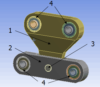
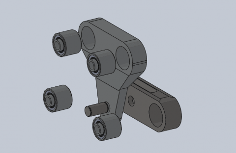
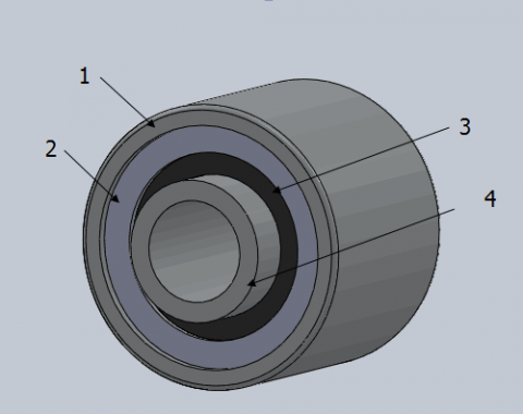
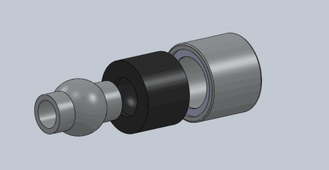
As shown in Figures 1 and 2, the Device consists of a triangular connector, a triangle connector seat, a pin and a rubber elastic joint. Specifically, the rubber elastic joint is composed of a bearing outer ring, a gasket, a rubber bushing and a bearing inner ring (Figures 3 and 4).
1-triangular connector; 2- triangular connector seat; 3- pin; 4- rubber elastic joint
Figure 1. Sketch map of Device structure
Figure 2. Exploded view of the Device
1-bearing outer ring; 2- gasket; 3- rubber bushing; 4- bearing inner ring
Figure 3. Sketch map of rubber elastic joint
Figure 4. Exploded view of rubber elastic joint
Linking up the brake magnet and suspension frame, the Device is responsible for the rigid positioning of the electromagnetic brake, transmitting the braking force uniformly to the adjacent suspension frame, damping the vibration of the transmission system, reducing the attraction of the electromagnetic brake to the guide rail, and compensating the dynamic relative motion between adjacent suspension frame and brake magnet [10, 11].
2.1 Prediction method
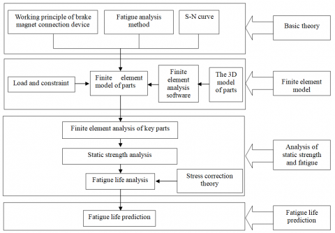
As shown in Figure 5, the fatigue life of the Device was predicted in four steps [12].
Step 1: According to the Device structure and functions, calculate the static load and fatigue load and plot the curve of stress (S) against the number of cycles to failure (N) (hereinafter referred to as the S-N curve) of the components.
Step 2: Import the 3D solid model of the component to the finite-element analysis software and establish a finite-element model of the Device.
Step 3: Considering the loads of the components and constraints of finite-element analysis, perform static analysis to see if the stiffness and strength of the components meet the requirements of train operation.
Step 4: Through finite element analysis, select the key points in the Device and determine their equivalent mean stress and stress amplitude. Based on the stress correction theory, analyse the fatigue strength of the Device and check if it satisfies the use requirements. Then, predict the fatigue life of each component.
Figure 5. Fatigue life prediction method
2.2 Parameters and analysis
In the Device, the triangular connector and triangle connector seat are made of AlMgSi1F28, the pin is made of 42CrMo4, the bearing inner ring is made of 42Cr, and the bearing outer ring is made of 45# steel. The metallic materials were analysed by a linear constitutive model, using the mechanical parameters in Table 1 below [13].
Table 1. Mechanical parameters of metallic materials
|
Parts |
Material |
Elastic modulus/GPa |
Poisson ratio |
Yield strength /MPa |
|
triangulation joint |
AlMgSi1 F28 |
70 |
0.33 |
250 |
|
triangle connector seat |
AlMgSi1 F28 |
70 |
0.33 |
250 |
|
bearing inner ring |
42Cr |
211 |
0.277 |
785 |
|
bearing outer ring |
45# |
209 |
0.269 |
355 |
|
pin |
42CrMo4 |
211 |
0.277 |
785 |
In addition, the rubber bushing is made of natural rubber, which is an incompressible, isotropic, super-elastic polymer with nonlinear stiffness features. For an isotropic material, the unit volumetric strain energy W is a scalar function of the deformation tensor [14]:
$W=W\left(I_{1}, I_{2}, I_{3}\right)$ (1)
where, I1, I2, and I3 are three independent variables of the Cauchy–Green deformation tensor. These variables are orthogonal second-order tensor invariants:
$I_{1}=\operatorname{tr} C=C_{i i}=\lambda_{1}^{2}+\lambda_{2}^{2}+\lambda_{3}^{2}$ (2)
$I_{2}=\frac{1}{2}\left[(\operatorname{tr} C)^{2}-\operatorname{tr} C^{2}\right]=\frac{1}{2}\left(I_{1}^{2}-C_{i j} C_{i j}\right)$
$=\left(\lambda_{1} \lambda_{2}\right)^{2}+\left(\lambda_{2} \lambda_{3}\right)^{2}+\left(\lambda_{3} \lambda_{1}\right)^{2} i, j=1,2,3$ (3)
$I_{3}=\operatorname{det} C=\left(\lambda_{1} \lambda_{2} \lambda_{3}\right)^{2}$ (4)
where, λ1, λ2 and λ3 are the elongation rates along the X, Y and Z axes, respectively. Since rubber is incompressible, the following relationship is valid:
$I_{3}=\left(\lambda_{1} \lambda_{2} \lambda_{3}\right)^{2}=1$ (5)
Rubber materials are usually described by thermodynamic statistical model and continuous medium mechanical model based on phenomenological theory. Here, the latter model is adopted for subsequent analysis. According to this model, the rubber bushing of the Device is isotropic if not deformed, that is, long molecular chains in the materials point to random directions. The unit volumetric strain energy W of the rubber bushing can be expressed as a function of the three strain invariants of the main elongation ratio λi or the deformation tensor Ii:
$W=\left(I_{1}, I_{2}, I_{3}\right)$ (6)
$W=\left(\lambda_{1}, \lambda_{2}, \lambda_{3}\right)$ (7)
The N-polynomial form model and Ogden form model are two popular phenomenological models. The unit volumetric strain energy W of the rubber bushing can be decomposed into strain partial energy and volumetric strain energy in the N-polynomial form model:
$W=f\left(\overline{I_{1}}-3, \overline{I_{2}}-3\right)+g(J-1)$ (8)
where, J is the ratio of pre-deformation volume to post-deformation volume. Assuming that $g=\sum_{i=1}^{N} \frac{1}{D_{i}}(J-1)^{2 i}$, the N-polynomial of the strain energy can be obtained through the expansion of Taylor formula:
$W=\sum_{i+j=1}^{N} C_{i j}\left(\bar{I}_{1}-3\right)^{i}\left(\overline{I_{2}}-3\right)^{j}+\sum_{i=1}^{N} \frac{1}{D}(J-1)^{2 i}$ (9)
The above N-polynomial is a complete polynomial representing the constitutive model of the rubber bushing, with N being the order of the polynomial. For the N-polynomial constitutive model, the initial shear modulus µ0and the initial bulk modulus k0 depend on the first-order coefficient of the polynomial:
$\mu_{0}=2\left(C_{10}+C_{01}\right), k_{0}=\frac{1}{D_{1}}$ (10)
where, N is 1, Mooney-Rivlin model of the rubber bushing can be obtained:
$W=C_{10}\left(\overline{I_{1}}-3\right)+C_{01}\left(\overline{I_{2}}-3\right)+\frac{1}{D_{1}}(J-1)^{2}$ (11)
The Mooney-Rivlin model is suitable for simulating the mechanical properties of rubber materials at small to medium strain. Here, the rubber bushing of the Device is analysed by the Mooney-Rivlin constitutive model, using the mechanical parameters in Table 2 [15].
Table 2. Mechanical parameters of rubber bushing
|
Part |
Material |
Mooney-Rivlin |
||
|
rubber |
NR |
C10 |
C01 |
D1 |
|
0.47 |
0.12 |
0.0001 |
||
2.3 Finite-element model and loading conditions
The fatigue load of the Device was determined according to the actual working conditions of high-speed maglev train (Table 3).
Table 3. Fatigue load of the Device
|
Fatigue strength loads /kN |
Times/ Thousands |
Frequency /Hz |
||
|
Fx |
Fy |
Fz |
100 |
2 |
|
0 |
4.5±3.0 |
0 |
||
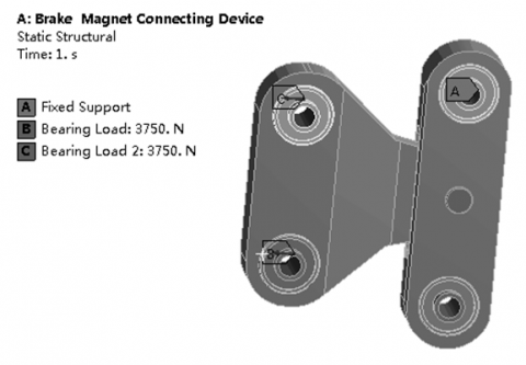
The 3D model of the Device was imported to ANSYS workbench, and applied with fixed constraints and loading conditions (Figure 6).
Figure 6. Loading conditions of the finite-element model on the Device
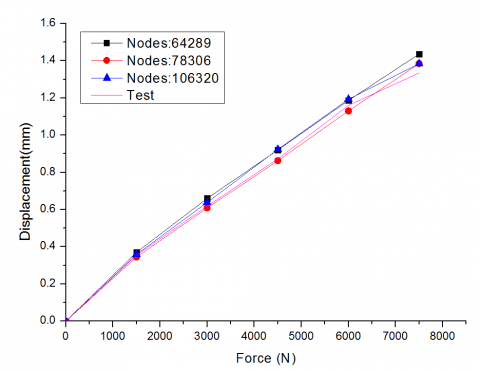
Figure 7. Comparison between the results of each finite-element model and the experimental data
Next, the 3D model was discretized by three different methods, yielding three finite-element models. The finite-element models each consists of 64,289, 78,306 and 106,320 grids. Figure 7 compares the results of each model with the experimental data. It can be seen that the three finite-element analyses shared similar results with a relative error lower than 10%. In particular, the 78,306-grid model and 106,320-grid model had very close results. The comparison shows that the results of the 78,306-grid model were basically consistent with the experimental results. The relative errors was lower than 6%, which is within the allowable range for engineering application. Therefore, this model was selected for the subsequent analysis.
2.4 Static analysis
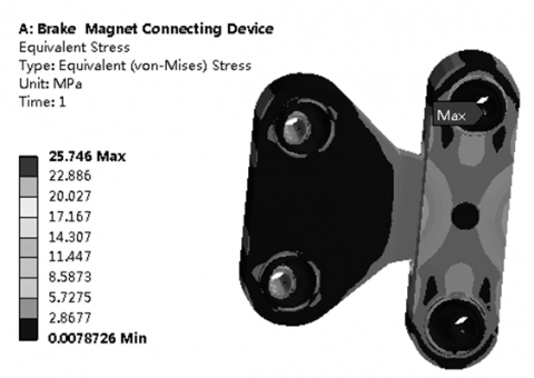
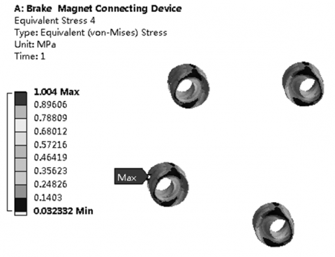
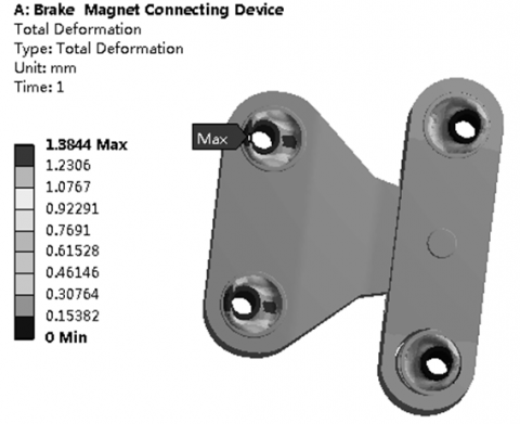
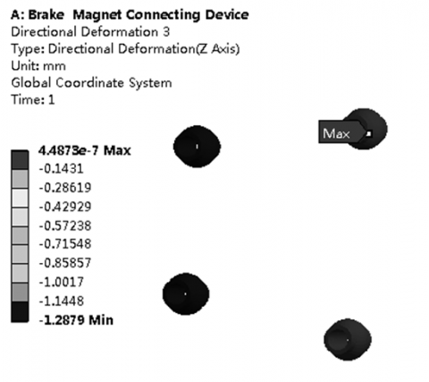
Under the fatigue load in Table 3, the stress results of the finite-element analysis on the Device are as follows: the maximum von Mises stress of the metallic components was 25.746MPa, occurring in the outer bearing ring (Figure 8); the maximum von Mises stress (1.004MPa) of the rubber bushing was observed on the inside (Figure 9); the maximum deformation of the Device took place in the rubber bushing, amounting to 1.384mm (Figure 10); the relative maximum displacement of the inner bearing ring along the Z axis was about 1.288mm (Figure 11).
Figure 8. Stress distribution of the Device
Figure 9. Stress distribution of the rubber bushing
Figure 10. Deformation distribution of the rubber bushing
Figure 11. Z-axis displacement of the inner bearing ring
2.5 Fatigue failure criterion for rubber bushing
The mechanical fatigue of rubber materials is essentially the reduction of the mechanical properties of rubber with the gradual propagation of cracks under dynamic stress. The previous studies have shown that rubber materials often suffer fatigue damages in areas of high stress and strain; these areas are prone to crack initiation under cyclic loading [16]. The fatigue failures of rubber materials mainly include abnormal cracking, glue failure and surface wrinkling. However, the occurrence of fatigue cracks does not necessarily mean that the rubber is in the state of fatigue failure [17]. With the increase in the number of loading cycles, the local damages of rubber will lead to continued decrease of the elastic modulus and strength of the material, until the strength fails to withstand the rated fatigue load [18, 19]. Since it is difficult to measure the elastic modulus of rubber bushing, the failure degree of the Device was determined by the static stiffness loss rate of the rubber element in the fatigue test [9]:
$\Delta K=\frac{K_{1}-K_{2}}{K_{1}} \times 100 \%$ (12)
where, ΔK is the static stiffness loss rate; K1 is the initial static stiffness; K2 is the post-test static stiffness.
At present, there is no uniform standard for static stiffness failure of rubber materials. According to load-bearing requirements of the Device, the fatigue failure criterion was set as 20% reduction in ΔK [20, 21].
Figure 12. Predicted fatigue life of the Device
2.6 Fatigue life prediction
The stress analysis results of the S-N curves on the metallic and rubber materials were imported to the finite-element analysis software. Coupled with the loading conditions in Table 3, the fatigue life of the Device was predicted and recorded in Figure 12.
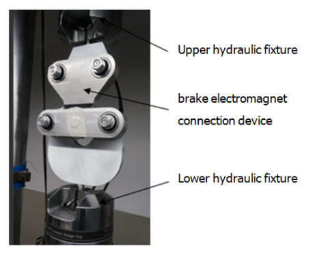
To validate the predicted fatigue life of the Device, a fatigue experiment was carried out under the same fatigue load on an MTS809 electro hydraulic servo fatigue test machine (MTS, US). The machine can perform fatigue tests on various materials under alternating loads and random loads (Figure 13). Under the frequency of 2Hz, the maximum load of 7,500N and the minimum load of 1,500N, the load variation during fatigue loading was plotted as Figure 14.
Figure 13. Fatigue test machine
Figure 14. Load variation during fatigue loading
During the fatigue experiment on the Device, the magnitude and axial displacement of the load applied to the Device were detected by the force sensor and the displacement sensor, respectively, and collected by the MTS809 computer system.
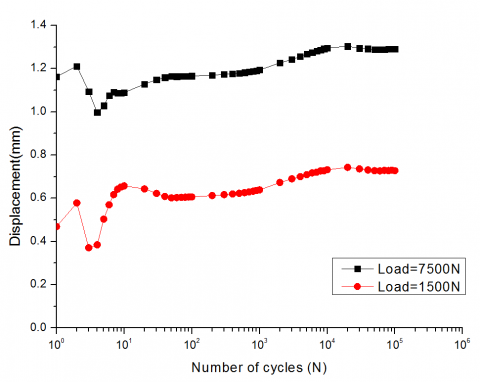
Figure 15 shows the axial displacements of the Device at the 100th, 1,000th, 10,000th and 100,000th cycles of fatigue loading. Figure 16 presents the axial displacements of the Device throughout the experiment under the maximum load of 7,500N and the minimum load of 1,500N.
Figure 15. Axial displacements of the Device at different cycles of fatigue loading
Figure 16. Axial displacements of the Device throughout the experiment
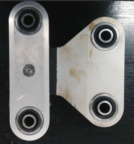
Figure 17. Photo on the Device after the fatigue test
As shown in the above figures, the axial displacement under the same load increased with the number of loading cycles. The initial static stiffness K1 of the rubber bushing was about 6.64kN/mm. At the 100,000th loading cycle, the static stiffness K2 of the rubber bushing dropped to 5.81kN/mm. This result is consistent with that of the finite-element analysis. After 100,000 loading cycles, the static stiffness loss rate of the bushing stood at 12.5%, which satisfies the engineering requirements. According to the photo on the Device after the fatigue test, there were no damage on the metallic and rubber components, indicating that the Device is still applicable to engineering projects.
Targeting the Device of high-speed maglev train, this paper calculates the static strength of the Device through finite-element analysis, predicted the fatigue life of the Device, and verified the predicted results through experiment. The research findings lay a solid theoretical basis for the minimization of product development cycle, optimization of product structure and safe operation of high-speed maglev train.
The author wishes to thank The National Key Technology R&D Program (2013BAG19B01), Shanghai Key Laboratory for R&D and Application of Materials and National Maglev Transportation Engineering R&D Center, under which the present work was possible.
[1] Lee, H.W., Kim, K.C., Lee, J. (2006). Review of maglev train technologies. IEEE Transactions on Magnetics, 42(7): 1917-1925. https://doi.org/10.1109/TMAG.2006.875842
[2] Sarunac, R. (1999). "Low speed" magnetic levitation vehicle in the US. In Proceedings of the 1999 ASME/IEEE Joint Railroad Conference (Cat. No. 99CH36340), pp. 130-143. https://doi.org/10.1109/RRCON.1999.762412
[3] Han, J.W., Kim, J.D., Song, S.Y. (2013). Fatigue strength evaluation of a bogie frame for urban maglev train with fatigue test on full-scale test rig. Engineering Failure Analysis, 31: 412-420. https://doi.org/10.1016/j.engfailanal.2013.01.009
[4] Xiu, R., Spiryagin, M., Wu, Q., Yang, S., Liu, Y. (2020). Fatigue life assessment methods for railway vehicle bogie frames. Engineering Failure Analysis, 116: 104725. https://doi.org/10.1016/j.engfailanal.2020.104725
[5] Seo, J.W., Hur, H.M., Jun, H.K., Kwon, S.J., Lee, D.H. (2017). Fatigue design evaluation of railway bogie with full-scale fatigue test. Advances in Materials Science and Engineering, 2017: 1-11. https://doi.org/10.1155/2017/5656497
[6] Chu, S.Y., Hwang, Y.J., Choi, S., Na, J.B., Kim, Y.J., Chang, K.S., Bae, D.K., Lee, C.Y., Ko, T.K. (2011). Design, manufacture and performance evaluation of HTS electromagnets for the hybrid magnetic levitation system. Physica C: Superconductivity and its Applications, 471(21-22): 1501-1505. https://doi.org/10.1016/j.physc.2011.05.225
[7] Lipski, A., Piotrowski, M., Mroziński, S. (2018). Weight reduction of the train by applying a new construction and testing process of the train car bogie. Proceedings of the Institution of Mechanical Engineers, Part C: Journal of Mechanical Engineering Science, 232(8): 1481-1492. https://doi.org/10.1177/0954406217744813
[8] Nejad, R.M., Shariati, M., Farhangdoost, K. (2016). Effect of wear on rolling contact fatigue crack growth in rails. Tribology International, 94: 118-125. https://doi.org/10.1016/j.triboint.2015.08.035
[9] Zhou, W., Huang, Y., Xu, C. (2013). Study on fatigue life prediction of rubber elastic element based on equivalent strain. Special Purpose Rubber Products, 34(6): 63-67.
[10] Ahmed, R., Jun, Y.L., Azhar, M.F., Junejo, N.U.R. (2014). Comprehensive study and review on maglev train system. In Applied Mechanics and Materials, 615(4): 347-351. https://doi.org/10.4028/www.scientific.net/AMM.615.347
[11] Ichikawa, H., Ogiwara, H. (1974). Design considerations of superconducting magnets as a Maglev pad. IEEE Transactions on Magnetics, 10(4): 1099-1103. https://doi.org/10.1109/TMAG.1974.1058512
[12] Shariati, M., Nejad, R.M. (2016). Fatigue strength and fatigue fracture mechanism for spot welds in U-shape specimens. Latin American Journal of Solids and Structures, 13(15): 2787-2801. https://doi.org/10.1590/1679-78253094
[13] Astakhov, V.P. (1994). Mechanical properties of engineering materials: relevance in design and manufacturing. In: Davim J. (eds) Introduction to Mechanical Engineering. Materials Forming, Machining and Tribology. Springer, Cham. https://doi.org/10.1007/978-3-319-78488-5_1
[14] Ogden, R.W. (1984). Nonlinear Elastic Deformations. New York: Dover Publications, Inc.
[15] Wang, J., Huang, Y., Sun, H., Xu, C.X. (2013). Prediction method for fatigue life of rubber component based on S-N and FKM standard. Computer Aided Engineering, 22: 184-187.
[16] Woo, C.S., Kim, W.D., Kwon, J.D. (2008). A study on the material properties and fatigue life prediction of natural rubber component. Materials Science & Engineering A, 483(1): 376-381. https://doi.org/10.1016/j.msea.2006.09.189
[17] Ali, A., Hosseini, M., Sahari, B. (2010). Continuum damage mechanics modeling for fatigue life of elastomeric materials. International Journal of Structural Integrity, 1(1): 63-72. https://doi.org/10.1108/17579861011023801
[18] Mars, W.V., Fatemi, A. (2002). A literature survey on fatigue analysis approaches for rubber. International Journal of Fatigue, 24(9): 949-961. https://doi.org/10.1016/S0142-1123(02)00008-7
[19] Kim, W.D., Lee, H.J., Kim, J.Y., Koh, S.K. (2004). Fatigue life estimation of an engine rubber mount. International Journal of Fatigue, 26(5): 553-560. https://doi.org/10.1016/j.ijfatigue.2003.08.025
[20] Moon, S.I., Cho, I.J., Woo, C.S., Kim, W.D. (2011). Study on determination of durability analysis process and fatigue damage parameter for rubber component. Journal of Mechanical Science & Technology, 25(5): 1159. https://doi.org/10.1007/s12206-011-0221-6
[21] Mirza, S., Hansen, P., Harris, J. (2013). Modelling and durability assessment for rubber components in rail vehicles. Plastics Rubber & Composites, 40(4): 185-193. https://doi.org/10.1179/1743289810Y.0000000041