Rabah Araria* | Abderrahmane Berkani | Karim Negadi | Fabrizio Marignetti | Mohamed Boudiaf
© 2020 IIETA. This article is published by IIETA and is licensed under the CC BY 4.0 license (http://creativecommons.org/licenses/by/4.0/).
OPEN ACCESS
The aim of this paper is the developments a DC/DC boost converter use to powered a DC/AC inverter with induction motor. A strategy of control of an induction motor (IM) used as a propulsion system of an electric vehicle (EV). The boost converter ensures an energy flux for an ideal operation of the vehicle even in case of battery voltage drop. The technique proposed is based on a direct flow and torque control diagram (DTC) and also introduces the fuzzy logic control (FLC) as well as the regulator in the place of a conventional PI regulator. The proposed approach covers the vehicle's torque demand and it optimizes the training performance. Simulation results on a test vehicle propelled by 38-kW induction motor showed that the proposed control approach operates satisfactorily. The analysis and simulations lead to the conclusion that the proposed system is feasible and can be tested on experimental bench.
fuzzy logic control (FLC), direct torque control (DTC), DC-DC converter, battery, DC-AC inverter, electric vehicle (EV), induction motor (IM) drives
Electric Vehicles (EVs) are a solution for the environmental problems caused by vehicles with internal combustion engines. The advantages of EVs include energy efficiency, virtually lack of pollution, and the availability of electric energy through electric distribution systems. Among disadvantages, they have low energy density and long charging time for the present batteries. Hence, optimal energy management is very important in EVs [1]. The other major factors include optimum design of the motor, selection of a proper drive, and optimal control strategy.
As a primary power source for small aircrafts, the Fuel cells can be used. However, combining an electrical storage system with the fuel cell can lead to a better performance [1, 2]. Therefore, rechargeable batteries are used as a secondary source to boost the fuel cell power during high power demand [3].
DC-DC converters are used to convert unregulated dc voltage to regulated or variable dc voltage at the output. They are widely used in switch-mode dc power supplies and in dc motor drive applications [4]. In dc motor control applications, they are called chopper-controlled drives. The input voltage source is usually a battery or derived from an AC power supply using a diode bridge rectifier. These converters are generally either hard-switched PWM types or soft-switched resonant-link types [5].
The DC-DC converter plays an important role in regulating the power flow in various system especially robots and electric vehicles. The battery bank voltage will vary with the operating conditions of the vehicle. Since the battery is directly connected to the main electrical node in the system it will make up the difference of current coming from the dc/dc converter and going into the motor drive [6].
The structure of the presented work is organized as follow: the description of the electric traction system and the physical modelling and control of different part of the proposed system with their equations model are set in section 2 and 3. The simulation results of the studied are presented in section 4. Section 5 summarizes the work done in the conclusion.
For EVs propulsion, the cage induction motor seems to be candidate that better fulfills the major above-mentioned features [5]. Induction motor drives control techniques are well treated in the literature. The most popular is the so-called vector control technique that is now used for high impact automotive applications (EV and Hybrid EV). In this case, the torque control is extended to transient states and allows better dynamic performances. Among these techniques, DTC appears to be very convenient for EV applications [1, 7].
DTC has the advantage of not requiring speed or position encoders and uses voltage and current measurements only.
Flux, torque, and speed are estimated. It also has a faster dynamic response due to the absence of the PI current controller [8, 9]. The input of the motor controller is the reference speed, which is directly applied by the pedal of the vehicle. Furthermore, DTC typical advantages are not sufficient. EVs induction motor drive has also to possess a high efficiency in order to extend the running distance per battery charge. Indeed, EV motors have a high torque-to-volume ratio and a wide speed operation range. As a consequence, these motors are characterized by their low inductance and high current density, so that they run at high speed and produce a high starting torque. Due to the low inductance coil design, the current ripple caused by PWM switching makes a significant amount of eddy current losses and hysteresis losses, especially in high-speed operation. If we simply neglect the iron losses, then it detunes the overall vector controller and results in an error in the torque control [10].
The structure of the presented work is organized as follow: The description of the electric traction system and the physical modeling of different part of our system with their equations model are set in section 2. The control strategy applied to EV is set in section 3. The simulations results of the studied are presented in section 4. Section 5 summarizes the work done in the conclusion.
2.1 Electric vehicle analysis
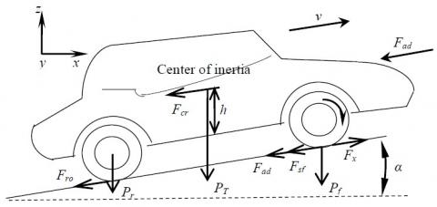
This section derives the driving power to ensure vehicle operation (Figure 1) [11-13].
The road load consists of:
$F_{w}=F_{r o}+F_{s f}+F_{a d d}+F_{c r}$ (1)
Figure 1. Elementary forces acting on a vehicle
The power required to drive a vehicle has to compensate the road load
$P_{v}=v F_{\omega}$ (2)
The mechanical equation (in the motor referential) used to describe each wheel drive is expressed by:
$J \frac{d \omega_{r}}{d t}+T_{B}+T_{L}=T_{e m}$ (3)
The following equation is derived due to the use of a reduction gear.
$\omega_{ {wheel}}=\frac{\omega_{m}}{G} \omega_{r}$ (4)
$T_{w h e e l}=T_{m} G \eta_{t}$ (5)
The load torque in the motor referential is given by :
$\omega_{{wheel}}=\frac{T_{ {Lwheel}}}{G} \omega_{r}=\frac{r}{G} F_{\omega}$ (6)
2.2 The proposed EV
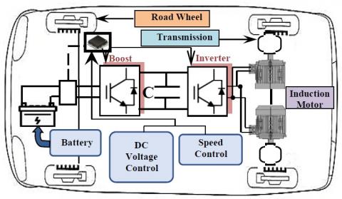
The proposed schema is based on the electric traction system which contains a DC voltage source supplied by a battery, a DC-DC boost converter connected to a DC-AC inverter controlled by the PWM technique and two electric induction motor controlled by FLC based DTC technique positioned behind the electric vehicle connected to the two wheels as shown in Figure 2.
Figure 2. Main components of electric vehicle
2.3 DC/DC boost converters
The DC-DC converter acts as an interface between the system and the load. A boost converter is implemented here; it extracts the maximum power point regardless the state of charge of the battery and the constraints applied to the electric vehicle. On changing the duty, cycle of the converter the source impedance can be matched with the load impedance to maximize the power efficiency [14]. This converter either bucks or boosts the output voltage with respect to the input voltage. The boost converter is designed based on the following formulas: The output voltage of the converter [15].
$V_{c}=V_{b a t} \frac{D}{(1-D)}$ (7)
For the design specification of the dc-dc boost converter parameters, the inductance L is given by:
$L_{c}=\frac{(1-D)^{2} R}{2 f}$ (8)
where, Vbat [V] is the input voltage battery, Vdc [V] is the output voltage fed motor, D is the duty cycle of the converters, R [Ω] is the load resistance and f [kHz] is the switching frequency.
The voltage ripple of the boost converters is computed from [4]:
$\frac{V_{c}}{V_{b a t}}=\frac{D}{R C f}$ (9)
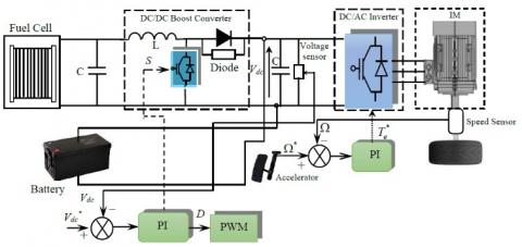
The boost converter, which increases the battery voltage to desired output voltage as required by load. The configuration is shown in Figure 3, which consists of a DC input voltage Vbat, inductor L, switch S, diode D, capacitor C for filter, and load resistance R.
When the switch S is ON the boost inductor stores the energy fed from the input voltage source and during this time the load current is maintain by the charged capacitor so that the load current should be continuous. When the switch S is OFF the input voltage and the stored inductor voltage will appear across the load hence the load voltage is increased. Hence, the load voltage is depending upon weather switch S in ON or OFF and this is depending upon the duty ratio D. The power is connected to the DC voltage bus via the unidirectional boost-buck DC/DC converter, as shown in Figure 3.
The power system will operate in charging, modes depending on the energy requirements and this mode is managed according to the DC bus voltage at the point of coupling. Consequently, the power system is required to provide necessary DC voltage level under different operating modes of the vehicle.
Figure 3. Battery, Fuel cell and DC/DC converter for electric vehicle control
During operation of the power electronics circuit, the switch S is activated and the converter operates as a boost circuit, and the switch S is activated and the converter operates as a buck circuit. When the voltage Vdc on the intermediate circuit is lower than the voltage reference, the regulator PI intervenes to increase it. The power budget of the intermediate circuit can be expressed by the following equation:
$P_{E V}=V_{d c} i_{d c}$ (10)
where,
PEV: is the power of electric vehicle (W);
idc: is the current absorbed by the electric vehicle (A);
The objective of the boost converter is to maintain constant voltage at the DC link, so the ripple in the capacitor voltage is much lower than the steady-state voltage.
2.4 Battery and DC/DC converter
This part of the vehicle ensures the charging and discharging of the battery through a DC/DC buck boost converter from the fuel cell arriving at the DC bus [8].
The System Storage (SS) is connected to the DC voltage bus via a bi-directional Boost DC/DC converter,as shown in Figure 4. The SS will operate in charging, dischargingor floating modes depending on the energy requirements and these modes are managed according to the DC bus voltage at the SS point of coupling. Consequently, theSS is required to provide necessary DC voltage level underdifferent operating modes of the vehicle. When charging,switch S2 is activated and the converter works as a boost circuit; otherwise, when discharging, switch S1 is activatedand the converter works as a buck circuit. When the voltageat the DC link is lower than the voltage reference, switch S1is activated. Alternatively, when the voltage at the DC link is higher than the voltage reference, switch S2 is activated. The FC-battery system response to transient variations is characterized by an inherent time constant [9]. In such cases, capacitors along the DC vehicle can act as virtual inertia to supply the shortfall or absorb the surplus of energy [15, 16]. The DC-link power balance can be expressed by the following differential equation:
$V_{d c} i_{d c}=P_{F C}+P_{b a t}-P_{E V}$ (11)
Neglecting the losses in the power converters, battery, filtering inductors and transformer and also the harmonics due to switching actions, the power balance of the integrated hybrid distributed generation system (DGS) with energy storage is governed by:
$V_{d c} i_{d c}=C V_{d c} \frac{d V_{d c}}{d t}=P_{F C}+P_{b a t}-P_{l o a d}$ (12)
Figure 4. DC/DC converter and battery control system
The objective of the battery converter is to maintain constant voltage at the DC link, so the ripple in the capacitor voltage is much lower than the steady-state voltage [14].
2.5 Induction motor model
The state space representation of the induction motor with the stator currents and the rotor flux linkages components as state variables can be written as [7, 17, 18]:
$\left[\begin{array}{c}\frac{d}{d t} i_{s d} \\ \frac{d}{d t} i_{s q} \\ \frac{d}{d t} \psi_{r d} \\ \frac{d}{d t} \psi_{r q}\end{array}\right]=\left[\begin{array}{c}-\left(\frac{R_{s}}{\sigma L_{s}}+\frac{1-\sigma}{\sigma T_{r}}\right) & 0 & \frac{L_{m}}{\sigma L_{s} L_{r} T_{r}} & \left(\frac{L_{m}}{\sigma L_{s} L_{r}}\right) \cdot \omega_{r} \\ 0 & -\left(\frac{R_{s}}{\sigma L_{s}}+\frac{1-\sigma}{\sigma T_{r}}\right) & -\left(\frac{L_{m}}{\sigma L_{s} L_{r}}\right) \cdot \omega_{r} & \frac{L_{m}}{\sigma L_{s} L_{r} T_{r}} \\ \frac{L_{m}}{T_{r}} & 0 & \frac{-1}{T_{r}} & p \omega_{r} \\ 0 & \frac{L_{m}}{T_{r}} & -p \omega_{r} & \frac{-1}{T_{r}}\end{array}\right] \left[\begin{array}{c}i_{s d} \\i_{s q} \\\psi_{r d} \\\psi_{r q}\end{array}\right]$$+\left[\begin{array}{cc}\frac{1}{\sigma L_{s}} & 0 \\ 0 & \frac{1}{\sigma L_{s}} \\ 0 & 0 \\ 0 & 0\end{array}\right]\left[\begin{array}{l}v_{s d} \\ v_{s q}\end{array}\right]$ (13)
where, Tr is the rotor time constant and s is the leakage coefficient. The electromagnetic torque and the rotor speed are given by:
$T_{e m}=\frac{3}{2} p \frac{L_{m}}{J L_{r}}\left(\psi_{r d} i_{s q}-\psi_{r q} i_{s d}\right)$ (14)
$\frac{d \omega_{r}}{d t}=\frac{p}{J} T_{e m}-\frac{B}{J} \omega_{r}-\frac{p}{J} T_{l}$ (15)
3.1 Direct torque control (DTC)
DTC is a control philosophy exploiting the torque and flux producing capabilities of ac machines when fed by a voltage source inverter that does not require current regulator loops, still attaining similar performance to that obtained from a vector control drive.
3.2 Behavior of the stator flux
In the (d, q) reference, the stator flux can be obtained by the following equation:
$\bar{V}_{s}=R_{s} \bar{I}_{s}+\frac{d}{d t} \bar{\psi}_{s}$ (16)
3.3 Behavior of the torque
The electromagnetic torque is proportional to the vector product between the vector of stator and rotor flux according to the following expression [18]
$T_{e m}=k\left(\bar{\psi}_{s} \otimes \bar{\psi}_{r}\right)=k\left|\psi_{s} \| \psi_{r}\right| \sin (\delta) $ (17)
with:
$\bar{\psi}_{S}$: is the vector of stator flux;
$\bar{\psi} r$: is the vector of rotor flux;
$\delta$: is the angle between the vectors of stator and rotor flux.
3.4 Development of the commutation strategy
In order to exploit the operation possible sequences of the inverter on two levels, the classical selection table of the DTC is summarized in Table 1.
Table 1. Selection table for direct torque control
|
∆ψs |
∆Tem |
S1 |
S2 |
S3 |
S4 |
S5 |
S6 |
|
1 |
1 |
V2 |
V3 |
V4 |
V5 |
V6 |
V1 |
|
0 |
V7 |
V0 |
V7 |
V0 |
V7 |
V0 |
|
|
-1 |
V6 |
V1 |
V2 |
V3 |
V4 |
V5 |
|
|
0 |
1 |
V3 |
V4 |
V5 |
V6 |
V1 |
V2 |
|
0 |
V0 |
V7 |
V0 |
V7 |
V0 |
V7 |
|
|
-1 |
V5 |
V6 |
V1 |
V2 |
V3 |
V4 |
Figure 5. Partition of the complex plan in six angular sectors SI = 1…
Figure 5 shows the commutation strategy suggested by Takahashi [3, 17], to control the stator flux and the electromagnetic torque of the induction motor.
3.5 Fuzzy logic control (FLC)
Fuzzy logic as a control theory is introduced in the control strategy of electric motors, as for adaptive control, neural networks, fuzzy control and neuro-fuzzy control [9]. Fuzzy control is simple and easy, does not require modelling, it is suitable for nonlinear systems that present variables and parameters variation.
Fuzzy logic and classical PI controllers are designed and applied to achieve reasonable rise time, settling time, overshoot and steady state error. The proposed method minimizes the error of the reference motor speed. Fuzzy logic has an advantage over other control methods due to the fact that it is not sensitive to plant parameter variations. In the conventional DTC method, the motor speed is controlled by a PI controller [10]. The proposed idea is to replace the conventional regulator with a fuzzy logic controller (Figure 9). The synoptic diagram of the fuzzy controller is exposed in Figure 6.
Table 2. Fuzzy logic rules (Df)
|
∆f |
d∆f |
|||||||
|
LN |
MN |
SN |
Z |
SP |
MP |
LP |
||
|
LN |
LP |
LP |
LP |
MP |
MP |
SP |
Z |
|
|
MN |
LP |
MP |
MP |
MP |
SP |
Z |
SN |
|
|
SN |
LP |
MP |
SP |
SP |
Z |
SN |
MN |
|
|
Z |
MP |
MP |
SP |
Z |
SN |
MN |
MN |
|
|
SP |
MP |
SP |
Z |
SN |
SN |
MN |
LN |
|
|
MP |
SP |
Z |
SN |
MN |
MN |
MN |
LN |
|
|
LP |
Z |
SN |
MN |
MN |
LN |
LN |
LN |
|
LP: Large Positive,
MP: Medium Positive,
SP: Small Positive,
Z: Zero,
SN: Small Negative,
MN: Medium Negative,
LN: Large Negative.
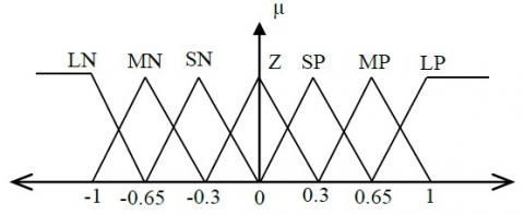
The fuzzy regulator anatomy is shown in Figure 7. FLC contains three phases: fuzzification, fuzzy control rules, and defuzzification. The difference of the frequency and its variation considered as input and the difference of the control signal considered as output.
The control signal is obtained by adding the value of the signal time from the previous iteration to the output signal of the fuzzy controller (Figure 8). The fuzzy controller rules are given in Table 2. The function forms are chosen optimally [9, 19-21].
Figure 6. Fuzzy logic control
Figure 7. Specification of a membership function
Figure 8. Proposed FLC schema bloc diagram
Figure 9. Basic direct torque control for induction motor drives
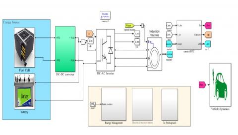
Numerical simulations have been carried out, on an EV propelled by a 38 kW induction motor drive which ratings are summarized in the appendix (Table 3). The objectives of the carried out simulations are to assess the efficiency and dynamic performances of the proposed control strategy (Figure 10).
First, Figure 11 show the induction motor speed controlled with FLC in DTC. At the beginning of the simulation process, different speed levels are applied to the control of the induction motor until it reaches its equilibrium state.
Second, Figure 12 shows the electromagnetic torque response and its zoom with PI and FLC, there are variations in the torque that corresponds to the variation of the reference speed at different times. Our order always intervenes to put the stable system.
Figure 10. The structure of the simulation model of the electric vehicle
Figure 11. Speed responses of EV
Figure 12. Electromagnetic torque responses
Figure 13. Stator current of IM during speed change
Figure 14. DC boost output voltage
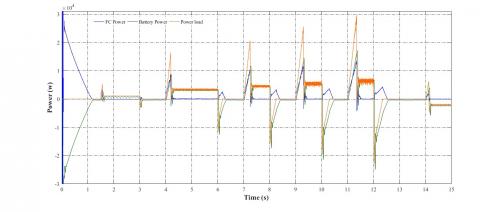
Figure 15. Power (battery, fuel cell and motor)
Figure 16. Battery voltage and SOC
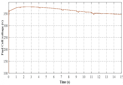
Figure 17. Fuel cell voltage
Figures 13, illustrate stator current of IM, oscillations appear at each period corresponding to changes in vehicle speeds.
The results of the electric dynamics vehicle during starting and with change the acceleration pedal position and a varied road profile demonstrate that FLC based DTC reduces the current ripples and large torque compared with the DTC based PI controller.
Figures 14 and 15 shows the output DC voltage from the boost and the power generation.
According to Figure 15, at t = [0, 1] s corresponds to the transient regime. An acceleration is applied at the different times t = [1, 5, 4, 7, 9, 11] s and a deceleration at the times [3, 6, 8, 10, 12] s. During acceleration, it is the battery and the fuel cell which intervene to give the power required by the load. During deceleration, the fuel cell begins to charge the battery and there will also be energy recovery due to braking and this in the form of potential energy.
These quantities ensure the power supply to the vehicle after the conversion of the DC bus through the inverter to supply the induction motor controlled by the FLC-DTC.
In Figure 16, we present the global (total) state of charge SOCG of storage devices. From 0 s to 15 s the SOC equals 79%, and the system operates with full charge.
The Figure 17 show the fuel cell voltage, this value is kept almost constant.
The control strategy with the FCL let the dc bus voltage and the current always maintained constant with high performance compared with the PI controller.
From these results, it can be said that the training system meets the shifting requirements at different levels.
Figures 14 and 15 shows the output DC voltage from the boost and the power generation, these quantities ensure the power supply to the vehicle after the conversion of the DC bus through the inverter to supply the induction motor controlled by the FLC-DTC.
In Figure 16, we present the global (total) state of charge SOCG of storage devices. From 0 s to 15 s the SOC equals 79%, and the system operates with full charge.
The Figure 17 show the fuel cell voltage, this value is kept almost constant.
The control strategy with the FCL let the dc bus voltage and the current always maintained constant with high performance compared with the PI controller.
From these results, it can be said that the training system meets the shifting requirements at different levels.
This work presented a detailed dynamic model of an EV that is associated with a DTC control use the FLC strategy for an induction motor drive, and the configuration of two DC-DC converter and DC-AC inverter for electric vehicle application to improve energy management.
DTC technique of three-phase IM has been used as a variable speed drive as well as a drive based on torque control because of its efficiency, reliability, reduced mathematical calculation and robustness in view of driving an electric vehicle. The performance of the system depends on the type of controller used.
Commonly used convention PI controller scheme has the disadvantage of increased peak overshoot, settling time, steady state error, and speed and torque variations under step change in load and restoration time to reach the command speed and torque. A modern scheme has been proposed in this paper to improve the drive system performances based the fuzzy logic control. The contributions of this article are:
Although this study has covered many issues and challenges of DTC additional work has been left for the future, some of those possible works are listed below:
The proposed approach can be validated with experimental setup easily using FPGA, DSP or Dspace platform.
|
AC |
Alternating Current |
|
C |
Capacitor, F |
|
D |
The duty cycle of the converters |
|
d, q |
Synchronous reference frame index |
|
DC |
Direct Current |
|
DTC |
Direct Torque Control |
|
EVs |
Electric Vehicles |
|
Fadd |
Aerodynamic drag force, N |
|
FC |
Fuel Cell |
|
Fcr |
Climbing and downgrade resistance force, N |
|
FLC |
Fuzzy Logic Control |
|
Fro |
Rolling resistance force, N |
|
Fsf |
Stokes or viscous friction force, N |
|
Fw |
Road load force, N |
|
G |
Gear speed ratio |
|
Ibat |
Battery Current, A |
|
idc |
converter Curent, A |
|
IM |
Induction Motor |
|
J |
Total inertia (rotor and load), kg m2 |
|
L (Lm) |
Inductance (magnetizing inductance) |
|
Lc |
Converter of inductance, H |
|
p |
pole-pair number |
|
Pbat |
Battery Power, W |
|
PFC |
Feul cell power,W |
|
PI |
Proportional Integral Controllers |
|
Pload |
Power of load ,W |
|
Pve |
Vehicle driving power, W |
|
PWM |
Pulse-Width Modulation |
|
r |
tire radius, m |
|
R |
Resistance, Ω |
|
ref ,* |
Reference index |
|
rpm |
Revolutions per minute |
|
S |
Duty Ratio |
|
SOC |
State of charge (%) |
|
SS |
System Storage |
|
TB |
Load torque accounting for friction |
|
Tem |
Electric motor torque |
|
TL |
Load torque |
|
Tr |
Rotor time constant (Tr= Lr/Rr) |
|
Ts |
Stator time constant (Ts= Ls/Rs) |
|
v |
Vehicle speed, m/s |
|
V (I) |
Voltage (current),V(A) |
|
Vbat |
Battery Voltage |
|
α |
Road angle slope, rad |
|
δ |
Steering angle, rad |
|
ηt |
Transmission efficiency |
|
σ |
Leakage coefficient, σ = 1 - L2 m/Ls Lr |
|
φ |
Flux of motor,Wb |
|
Ψr,s |
vector of flux (stator and rotor) |
|
ωr |
Electric motor mechanical speed, rad/s |
|
ωwheel |
wheel speed, rad/s |
Table 3. Induction motor parameters
|
Components |
Rating values |
|
Rated power |
38 kW |
|
Stator resistance |
Rs=0.01965 Ω |
|
Rotor resistance |
Rr=0.01909 Ω |
|
Stator/rotor inductance |
Ls=Lr=0.0397 H |
|
Mutual inductance |
Lm=1.354 H |
|
Moment of inertia |
J=0.09526 Kg.m2 |
|
Viscous friction |
f=0.05479 N.m/rad/sec |
|
Number of pole pairs |
p=2 |
[1] Ehsani, M., Gao, Y., Longo and, S., Ebrahimi, K. (2018). Modern Electric, Hybrid Electric, and Fuel Cell Vehicles. CRC Press, 3rd Edition, Boca Raton, 572 pages. https://doi.org/10.1201/9780429504884
[2] Araria, R., Negadi, K., Marignetti, F. (2019). Design and analysis of the speed and torque control of IM with DTC based ANN strategy for electric vehicle application. TECNICA ITALIANA-Italian Journal of Engineering Science, 63(2-4): 181-188. https://doi.org/10.18280/ti-ijes.632-410
[3] Kimiabeigi, M., Widmer, J.D., Long, R., Gao, Y., Goss, J., Martin, R., Lisle, T., Soler Vizan, J.M., Michaelides, A., Mecrow, B. (2016). High-performance low-cost electric motor for electric vehicles using ferrite magnets. IEEE Transactions on Industrial Electronics, 63(1): 113-22. https://doi.org/10.1109/TIE.2015.2472517
[4] Ghosh, D., Willich, C., Kallo, J. (2018). Development of a novel AC hybrid concept for a fuel cell-battery hybrid electric aircraft with power electronics switches. 2018 14th Int Conference on Power Electronics (CIEP): IEEE, Cholula, Mexico, pp. 105-110.
[5] Amir, A., Che, H.S., Amir, A., El Khateb, A., Rahim, N.A. (2018). Transformerless high gain boost and buck-boost DC-DC converters based on extendable switched capacitor (SC) cell for stand-alone photovoltaic system. Solar Energy, 171: 212-222. https://doi.org/10.1016/j.solener.2018.06.078
[6] Alloui, H., Berkani, A., Rezine, H. (2010). A three level NPC inverter with neutral point voltage balancing for induction motors direct torque control. The XIX International Conference on Electrical Machines-ICEM 2010: IEEE, Rome, Italy, pp. 1-6. https://doi.org/10.1109/ICELMACH.2010.5608161
[7] Liu, H., Zheng, Z.D., Li, Y.D., Yao, R.D., Xu, Z. (2018). Urban rail transit power system integrated with electric vehicles based on CLLC resonant and buck-boost converter. 2018 IEEE International Conference on Electrical Systems for Aircraft, Railway, Ship Propulsion and Road Vehicles & International Transportation Electrification Conference (ESARS-ITEC), pp. 1-7. https://doi.org/10.1109/ESARS-ITEC.2018.8607797
[8] Camara, M., Fodorien, D., Gualous, H., Bouquain, D., Miroui, A. (2008). Hybrid sources control for electric drives traction applications. 19th IEEE Int Symposium on Power Electronics, Electrical Drives, Automation and Motion 2008. pp. 11-13.
[9] Ali, A.K.M. (2018). Commande de Vitesse de Dtc-Svm Pour Entraînement de Moteur à Induction à L'aide d'un Contrôleur Fuzzy PI à Autotunisation Ann Anfis. J. of Al-Qadisiyah For Engineering Science, 11(3). https://doi.org/10.30772/qjes.v11i3.562
[10] Blange, R. (2015). Fuzzy logic controller replacing two level flux hysteresis for DTC of IM for EV applications. Advanced Research in Electrical and Electronic Engineering, 2(11): 51-55.
[11] Negadi, K., Mansouri, A., Marignetti, F., Touan, M. (2014). A MRAS based estimation method with artificial neural networks for high performance induction motor drives and its experimentation. International Review of Automatic Control (IREACO), 7(2): 123-130.
[12] Ghezouani, A., Gasbaoui, B., Ghouili, J. (2018). Modeling and sliding mode DTC of an EV with four in-wheel induction motors drive. 2018 Int Conference on Electrical Sciences and Technologies in Maghreb (CISTEM), pp. 1-9.
[13] Nguyen, T.S., Song, J., Yu, L., Fang, S., Tai, Y., Lu, Z. (2018). Design and development of a real-time simulation and testing platform for a novel seamless two-speed transmission for electric vehicles1. Journal of Dynamic Systems, Measurement, and Control, 141(2): 021007-12. https://doi.org/10.1115/1.4041358
[14] Oh, Y., Park, J., Lee, J., Eom, M.D., Park, S. (2014). Modeling effects of vehicle specifications on fuel economy based on engine fuel consumption map and vehicle dynamics. Transportation Research Part D: Transport and Environment, 32: 287-302. https://doi.org/10.1016/j.trd.2014.08.014
[15] Araria, R., Negadi, K., Boudiaf, M., Marignetti, F. (2020). Non-linear control of DC-DC converters for battery power management in electric vehicle application. Przegląd Elektrotechniczny, 2020(3): 82-88. https://doi.org/10.15199/48.2020.03.20
[16] Aziz, S., Wang, H., Liu, Y., Peng, J., Fu, X. (2018). An approach to kinetic energy recovery system for electric vehicle considering SC and Bi-directional converters. 2018 IEEE Innovative Smart Grid Technologies - Asia (ISGT Asia), pp. 1273-7. https://doi.org/10.1109/isgt-asia.2018.8467846
[17] Jyotheeswara, R.K., Natarajan, S. (2018). Energy sources and multi-input DC-DC converters used in hybrid electric vehicle applications – A review. International Journal of Hydrogen Energy, 43(36): 17387-408. https://doi.org/10.1016/j.ijhydene.2018.07.076
[18] Allirani, S., Ja gannathan, V. (2014). Direct torque control technique in induction motor drives-A review. J. of Theoretical & Applied Information Technology, 60(3).
[19] Sood, A., Gupta, N. (2019). Direct torque control scheme of induction motor drive using space vector modulation. International Journal of Recent Advances in Science and Technology, 6(1): 1-7.
[20] Ali, A.K.M. (2018). Commande de Vitesse de Dtc-Svm Pour Entraînement de Moteur à Induction à L'aide d'un Contrôleur Fuzzy PI à Autotunisation ANN ANFIS. J of Al-Qadisiyah For Engineering Science, 11(3). https://doi.org/10.30772/qjes.v11i3.562
[21] Negadi, K., Mansouri, A., Khatemi, B. (2010). Real time implementation of fuzzy logic based MRAS observer for speed sensorless vector control of induction motor. International Review of Electrical Engineering (IREE), 5(4): 1519-1528.