Anil A. Sequeira | Saif Mohammed | Avinash A. Kumar | Muhammed Sameer | Yousef A. Kareem | Krishnamurthy H. Sachidananda*
OPEN ACCESS
The Battery Operated fork lift is an improved version of lifting and carrying the load which needs to be transferred from one place to another. This advanced technology has brought a new revolution in the mechanical industries and most commonly used in heavy Engineering companies. These forklift vehicles had revolutionized ware-housing practices used in the middle of the 20th century. For a long time, semi- automatic type of material handing systems being used. In semi automatic material handling, the system was manually controlled. The design of forklift has revolutionized warehouse work and it is practicable for one person to move hundreds of kilograms at once. These well maintained and safely operated forklift has made lifting and transporting cargo items very easily. The main purpose of this paper is to design and fabricate a forklift machine which is new and different from existing designs. This designed forklift uses a rechargeable battery which means it is powered completely by electricity. From the design of forklift, it can be concluded that this machine is capable of lifting a load of 100 Kgs. The findings of this research show that the designed machine can be used in small scale industries.
battery operated, automatic, steering, four wheel
Forklift is defined as an industrial truck which is capable of lifting hundreds of kilograms. Forklift is commonly used in warehousing and manufacturing and it consists of two metal forks at the front of the vehicle in order to lift and transfer the load. The way the load is lifted in case of forklift is in such a way that the operator is going to move forward the vehicle until the two forks push under the cargo and then it is lifted by operating the forks [1]. Sometimes forks are also known as blades and made of steel and is capable to lift a few tons.
The power to operate the forklift are either given using gasoline or electricity [2]. Electric forklift depends on batteries to operate as compared to Gasoline or propane forklifts. These gasoline or propane forklifts are much stronger or faster as compared to electric forklifts, but considered to be difficult to maintain, and it is also fuel efficient. Forklifts are specified as the maximum weight or forward center of gravity. Sachin et al. [3] have designed and developed robotic forklift to lift palletized materials which is capable of handling outdoor storage facilities. They designed this robotic forklift using radio frequency technology in order to increase the visibility and human safety. They concluded that the designed forklift can be operated from a distance of 15 meters. Wade and Waghchore [4] has studied 3 wheel battery operated forklift. They developed an image module with remote technology for better visibility and safety of operator. They concluded that the designed and developed system is working satisfactory as well as the power consumed by their designed machine is less as compared to other machines. Wang et al. [5] has studied and designed electric elevating mechanism for lifting the equipment using forklift based principle. They have done the dynamic simulation and analysis for fork arm. They developed a mathematical model based on simulation and analsysis and summarised the two types of lifting systems. Kumar et al. [6] has designed and developed a pneumatic operated forklift. They designed the forks of a forklift using pneumatic powered cylinders in order to lift the load. Each fork was operated using a separate cylinder. They concluded that there designed forklift can be used in small scale industries and can lift pallet load of 60 Kgs. Pan et al. [7] have studied the structural parameters in case of forklift. They designed the hydraulic systems and calculated the structural parameters of the oil cylinders using mathematical equations. They concluded that lifting oil cylinders structural parameters have great significance to improve the working efficiency of the designed system. Kim et al. [8] have studied hybrid propulsion system in case of forklift. They studied the torque, speed and operating systems in case of hybrid propulsion system to improve the fuel economy. They concluded using simulation results in order to improve fuel economy using hybrid propulsion system. Roskam [9] has studied the mechatronics systems in case of forklift. They studied the forklift considering hydraulics as well as AC and DC drives and embedded controller. They concluded that from the measurements it is possible to study the behavior of the lifting operation. Jagtap et al. [10] has studied and developed a portable forklift for handling materials in industries which is commonly used in small industries. They concluded that the remote controlled forklift is not only cost effective but will increase productivity. Kumar et al. [11] has designed and fabricated mini forklift using pulley based mechanism. They used 4 motors in order to control the forklift in four directions. They used wi-fi based technology to run this forklift. They concluded that the prototype model they developed is cost effective. Abdellatif et al. [12] has designed and developed an autonomous forklift. They developed a robot to perceive 3 dimensional movement in order to lift the material from one place to the other place. They concluded that robot based forklift can lift load from the source and load it to the target locations. Vaidya et al. [13] has designed and developed pedal operated forklift in order to transport medium load weights fast and efficient way and consuming low power and lesser space. They concluded that the efficiency of this forklift is good and much more capable in handling material as compared to bare hand. Salunke et al. [14] has designed hydraulic forklift circuit design using simulation software to study power steering and cylinders. They tested using static and dynamic loads the power steering systems and cylinders. They concluded that the design is safe to implement under working conditions. Shen et al. [15] has studied optimal steering system in case of forklift. According to the study the reciprocating unbalance and gas pressure torque are the main source of vibration in case of forklift. They concluded by giving design guide lines.
Based on the above literature review, it is observed that many researchers have worked on design and fabrication of forklift commonly used in industries. Some researchers also worked on steering systems, cylinders as well as software analysis of the different components of forklift systems. The major accidents in case of forklift is happening due to poor visibility and human errors and hence in order to solve these issues, some researcher have designed remote controlled as well as web-cam sensors which mainly focuses over the safety of the operator as well as surrounding environment. Also, many researchers have worked on the ergonomically comfort position of the operator and also to reduce time for up/down movement. Also, from the research review it is known that maximum amount of power is required and is wasted during lifting a load or heavy material. So, based on above limitations, in this research work we made an attempt to design and fabricate forklift which was based on rechargeable battery. From this research findings it is possible to use rechargeable battery in case of forklift design.
In this research work design and fabrication of the forklift, the section 2 discusses about methodology and the section 3 discusses about component selection followed by results and discussions, conclusion and references.
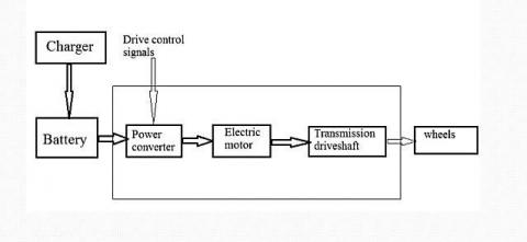
The methodology used for the design and fabrication of forklift is as follows. A total load of 100 Kgs is considered as the lift during the working process. The driving force was given by a single motor of 500 rpm, 36 W. This motor was selected based on efficiency of the motor which is calculated as mechanical output power divided by electrical input power. The efficiency of the motor for calculations was considered as 10% and output mechanical power is calculated considering the input electrical motor power as 0.22 A × 12 V which is equal to 2.64 W. So, based on above electric motor power the output mechanical power was calculated considering 500 rpm of the motor along with angular velocity and was estimated to be about 0.263 W. In order to power the motor and winch 2 car lithium ion batteries, each of 12 V being used. The circuit block diagram of forklift is as shown in Figure 1. The components specifications is as shown in Table 1.
Figure 1. Circuit layout block diagram of forklift
Table 1. The components specifications
|
Sl. No |
Components |
Quantity |
|
1 |
D C motor, 500 W, 36 V |
1 |
|
2 |
Lithium ion batteries, 12 V, 12 Ah |
2 |
|
3 |
Steel frame 83” × 21” × 45” |
1 |
|
4 |
Motor Controllers 36 V |
2 |
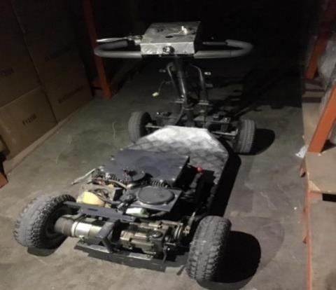
The main base frame of this forklift designed is the chassis, it incorporates all other components of the electric forklift. Hence, chassis is considered as the structural skeleton of this machine. The chassis in the forklift design is considered to be important and is manufactured using from ERW steel bar (Refer Figure 2). As all the other components are placed inside the chassis, it gives maximum protection and helps to maintain the forklift portable as well as light weight.
Figure 2. Chassis of forklift
3.1 Drive train
The drive train is one of the most important system in the forklift as it allows the vehicle to move from one place to other. The driver is going to steer the front wheel in the desired direction whereas the power to the forklift is given to the rear wheel which is powered by the battery. The drive train of this forklift consists of many components in order to drive the driving wheels and also it converts electrical energy into mechanical energy. The energy from the drive train is consisting of a reduction drive in order to convert speed into torque. The output of the reduction drive is supplied to the wheels of the forklift for movement.
3.2 Power supply
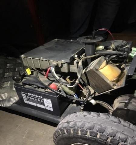
This forklift machine consists of rechargeable battery and the charging unit as shown in Figure 3. Also, it is known that power supply available is 230 V AC. These batteries act as power source for driving the forklift. A battery capacity of 12 V, 38 AH which is capable to run for 20 hrs have been used and the designed forklift consists of 2 batteries. This machine is equipped with electric circuit in order to convert AC into DC and to charge the batteries. The provision for charging the battery have been provided in such a way that it can be plugged into AC supply during recharging.
Figure 3. Rechargeable battery
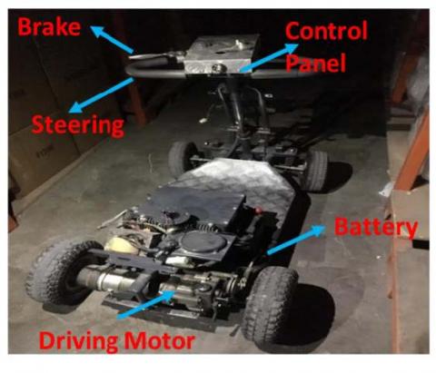
Figure 4. Control panel of forklift
3.3 Control system
The control system is used in order to move the vehicle front or back as well as to right and left. This helps to navigate the vehicle in different directions. It also facilitates the switching the machine on or off. (Refer Figure 4). The power to the drive wheel is provided by the motor which in turn is connected to the rear wheel using gearing arrangement. This machine is also equipped with an emergency switch in which it is possible to cutoff the power. This emergency switch is also located in the control system designed for this forklift machine.
3.4 Steering system
Since the machine designed is for 4 wheel forklift, the major focus of the research work is on steering systems (Refer Figure 5). The steering mechanism consists of differential so that the designed vehicle can smoothly run while taking turns. The steering system designed in this forklift machine consists of steering wheel and consists of gears, linkages and the cables connected to the drive wheel assemblies and hence requires proper maintenance.
Figure 5. Steering system
4.1 Numerical analysis
Volume
Fork has a side plate at its base. As there are two forks the volume of which will be 1200 cm3. So, total volume of base will be 2400 cm3.
V= 2 (l×b×t)
= 2 (82×10.5×0.7)
= 1205 cm3
The upper body of the forklift has total 4 plates welded together.
Front plate = (L×H×T) = (64×27×0.7) = 1200 cm3
Upper plate = (35×18×0.7) = 440 cm3
2 side plates= 2 (27×18×0.7) = 340 cm3
Total volume of body above the fork = 1200+440+340= 1980 cm3.
The total volume of the forklift handle
Long Hollow Handle = P/4 (do2-di2) × L
=P/4(32-2.32) ×90 = 260 cm2
Gripping Handle = 70 cm3
Total Volume = 2400+2000+250 =4650 cm3
In order to determine the power of the batteries. Assuming the system is 100% efficient, (i.e. no resistive losses in cables, or internal resistance from battery)
Power (Watts) = I (Amps) * V(Voltage)
= 150A * 12V
= 1800 Watts
In order to determine the torque, the maximum torque calculated when forklift starts
T=0.05*1500*10*0.17/2 = 63.75 N-m.
According to the demand speed of 2.5 − 3 km/h, the wheel speed is calculated as:
n=50v/3πd = 78-93 rev/min
The testing was done for determining the load that can be carried by the forklift. The result analysis shows that the vehicle can carry up to 100 kgs and it can run up to 9-10 hrs with a fully charged battery.
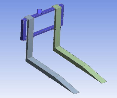
Figure 6. Isometric view of the fork
Figure 7. Pressure on the fork
Figure 6 and 7 shows the isometric view and pressure on the fork. There are two forks installed in front of the support frame and the support frame is attached to the fork lid thought a pillar which is rotatable to provide the lifting fork system with a rotation movement. There are two axles connecting the fork support frame with its two motors and rack fixer. One motor lifts the fork lid and the other one (rack motor) moves the whole system horizontally. The down rack fixer connects the fork lid with operator cabin, to make sure the entire system is stable in front of the truck. Figure 8 shows the deformation for a load of 100 Kg. From this it is observed that the deformation is maximum at the end of the fork. From this figure it can be stated that the maximum deformation at the end of the forklift is 0.00115 m whereas the portion which is supporting the forklift is having a maximum deformation of 0.000128m. From this analysis it can be concluded that the forklift design is safe from the deformation point of view.
Figure 8. Deformation at 100 Kg
4.2 Stability analysis
In the stability analysis, analysis tools being used is to ensure that the forklift meets the safety requirements of its operations. The mass property calculations tool is used which gives us the volume, mass, centre of mass, principal moments, axes of inertia and other properties of the model. The above properties of the model are calculated by assigning material properties to each individual component as each having its own function and performance. Also, the mass properties for both the fork have been calculated in order to ensure safety for the operator during its lifting as well as placing movement. In order to ensure safety of the forklift under static condition, the forklift is usually designed so that center of gravity will remain within the zone of the triangle as referred in the text [16] and has been checked in our design for stability in the forklift. We also performed those measurements to ensure the stability of our forklift under resting and loading conditions.
4.3 Mass property calculations
Before using the design tools, it is required to calculate the mass properties of the model and assign material properties to every individual component. Each part would use a different material when manufactured due to its own function in the entire system. After that, the mass and centre of gravity of the forklift is been computed followed by FEM analysis. Also, the design of forklift based on analysis shows that the deformation and average stress (Static structural) were within the limits and hence it is safe. Counterweight plays a very important component of the forklift. It is the part that makes sure the forklift can maintain its balance while working. So, the battery is installed in the place of the counterweight.
4.4 Forks stress analysis
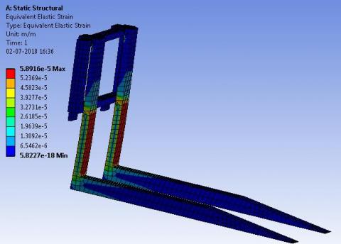
This section covers both the static and dynamic (fatigue) analysis of the forks. For the static analysis, it is already known that the maximum loading capacity of this forklift is 100 Kg. There are two forks and the structure is symmetrical, so each one of them carries half of the force, which is approximately 500 N. Figure 9 shows the equivalent strain of the fork. From this figure it is observed that the maximum deformation is 5.89 × 10⁻⁵. From this it is observed that the maximum deformation is within the safety consideration. Figure 10 shows the equivalent stress (Von-Mises) of the fork and from this it is observed that the maximum stress is 11.7 MPa.
Figure 9. Equivalent strain of the fork
Figure 10. Equivalent stress of the fork
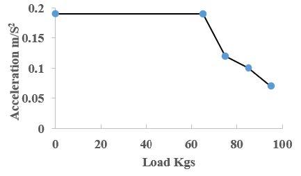
Figure 11. Load versus acceleration
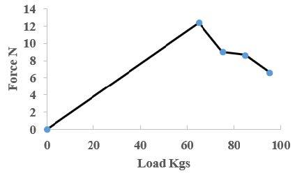
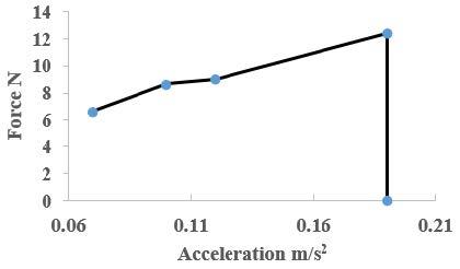
The load weight, load distribution size and shape of the forklift plays an important role during the movement of the vehicle while in operation. So, in order to study the stability of this vehicle in terms of velocity, acceleration a graph of load versus acceleration, velocity and force have been plotted as shown in Figures 11-13. From Figure 11 it is observed that as the load on the forklift increases from 0 to 100 kg, the acceleration initially remains constant and then decreases as the load on the vehicle increases. Similarly, from Figure 12 it is observed that the forklift can handle approximately 70 Kgs load without compromising the performance of the forklift. This occurs due to insufficient torque exerted by the motor as the load increases above 70 Kgs. Figure 13 shows the force versus acceleration diagram and from this it is observed that as the force increases, acceleration also increases up to a force of 12 N.
Figure 12. Load versus force
Figure 13. Force versus acceleration
In this research work, design and fabrication of forklift have been studied. From this research paper the following conclusions have been drawn.
[1] Panara, K.S., Mishra, V.R., Patel, A., Patel, T.B., Dhivar, K.R. (2015). Construction of battery operated forklift. International Journal of Science Technology and Engineering, 2(4): 1-5.
[2] Allwyn, L.M., Karan, K.N., Ganesh, A.B., Prathamesh, B.G., Omkar, K.S., Abhijeet, N.N. (2018). Design and development of mechanical forklift. International Research Journal of Engineering and Technology, 5(3): 1125-1136.
[3] Sachin, U.S., Tushar, S.S., Sachin, L.S., Prashant, K.R. (2014). Design, development and modelling of forklift. International Journal of Engineering Research and Technology, 3(4): 1234-1238.
[4] Wade, R.R., Waghchore, R.K. (2018). Battery operated 3 wheel drive forklift for industrial warehouse. International Journal for Scientific Research and Development, 5(12): 670-673.
[5] Wang, Y., Zhao, D.X., Wang, L., Zhang, Z.X., Wang, L.L., Hu, Y.J. (2016). Dynamic simulation and analysis of the elevating mechanism of a forklift based on a power bond graph. Journal of Mechanical Science and Technology, 30: 4043-4048. https://doi.org/10.1007/s12206-016-0817-y
[6] Kumar, N.K., Arun, M., Kumar, K.R. Sabiranathan, R., Yuvaraj, K. (2015). Design and fabricated pneumatic operated forklift. International Journal of Engineering Research and Science and Technology, 4(1): 291-296.
[7] Pan, L., Du, Q.L., He, C.S. (2015). Design research on hydraulic system of working device of a forklift. 5th International Conference on Advanced Design and Manufacturing Engineering ICADME (2015), pp. 1813-1817.
[8] Kim, S., Choi, S., Lee, J., Hong, S., Yoon, J. (2013). A study of hybrid propulsion system on forklift trucks. 2013 World Electric Vehicle Symposium and Exhibition, IEEE, Barcelona, Spain. https://doi.org/10.1109/EVS.2013.6914737
[9] Roskam, R. (2018). Development of a forklift for research and education in mechatronics. 2nd International Conference on Mechatronics Systems and Control Engineering, 21-23: 17-21. https://doi.org/10.1145/3185066.3185070
[10] Jagtap, K.S., Londhe, S.D., Khujat, S.M., Koli, P.S., Desai, A.A. (2018). Design and fabrication of battery operated remote controlled articulated forklift. International Journal of Advance Research in Science and Technology, 7(1): 809-813.
[11] Kumar, K.S., Reddy, A.S., Reddy, G.S.K., Reddy, G.S.S. (2018). Fabrication of mini forklift using Wi-Fi module. Journal of Emerging Technologies and Innovative Research, 5(9): 613-617.
[12] Abdellatif, M., Shoeir, M., Talaat, O., Gabalah, M., Elabably, M., Saleh, S. (2018), Design of an autonomous forklift using Kinect. MATEC Web of Conferences, 153: 1-5. https://doi.org/10.1051/matecconf/201815304005
[13] Vaidya, A., Rotliwala, K., Prajapati, M., Patel, N., Rajpurohit, R. (2016). Design of Pedal operated wheel drive forklift. International Journal of Design and Manufacturing Technology, 9(1): 17-22.
[14] Salunke, G., Bell, P., Chore, S., Ghatol, C., Vaishnav, S. (2018). Designing of hydraulic forklift circuit in automation studio using manufacturer’s catalogue. International Journal of Current Engineering and Technology, 8(5): 1210-1219. https://doi.org/10.14741/ijcet/v.8.5.3
[15] Shen, Y., Chu, B. Liu, D.C., Zhu, C.A. (2015). Optimization of steering system of forklift vehicle for idle performance. Mathematical Problems in Engineering, Hindawi, 2015: 1-9. http://dx.doi.org/10.1155/2015/313182
[16] Yuru, S., Ibrahim, Z. (2015). Design and analysis of new flexible and safe forklifts. Thesis, North Eastern University, Boston.