Said Belhadj* | Karim Belmokhtar | Kaci Ghedamsi
OPEN ACCESS
In this paper, we present a new approach for the optimization of energy management of the hybridization of three sources battery/Fuel Cell/Photovoltaic (B/FC/PV) vehicles configurations in order to reduce hydrogen consumption. An advanced control optimization strategy is proposed using an artificial intelligence (AI) algorithm carried out in a Matlab/Simulink environment. The power control of the fuel cell is obtained by regulating the powers of the two other sources as well as the state of charge (SOC) of the battery with hybridization via a parameter PH (parameter of hybridization). The regulation of the power of both battery and the solar PV system is achieved to the regulation of the DC bus voltage according to the reference current of the fuel cell during the optimization of the output value via a parameter PO (parameter of optimization). The activation outputs of the three sources are generated by the AI algorithm developed while including the dynamics and the profile/condition of the road as well as the demand of the vehicle. An optimization is proposed via the introduction of two parameters PH and PO, during phases of high energy demands. The results show that the proposed strategy will provide a new approach for the advanced energy management system for hybrid vehicles.
hybrid electric vehicle, energy management strategy, hydrogen economy, autonomy, lifetime, efficiency, artificial intelligence algorithm, battery/FC/PV
Nowadays, electric vehicles (EVs) are widely considered as an effective and one of the most suitable alternatives to reduce greenhouses gas (GHG) emissions in transportation applications. This is mainly due to a reduction of local and global emissions, given that these are not produced during operation, but during the electricity production stage, which uses more efficient processes. Therefore, the switch from internal combustion engines to EVs will certainly lead to changes in the transportation sector in what concerns its environmental impacts for society [2, 3].Proton exchange membrane fuel cells (PEMFC) are widely used in transportation applications. One can cite the advantages of this FC as lower operating temperature, which is an important parameter in the starting of the vehicle. PEMFC technology has been widely used, especially in vehicular applications where the power delivered is between a few kW to several hundred kW. There are several types of commercially available FCs, such as proton exchange membrane (PEM) FCs, solid oxide (SOFCs), alkaline FCs, direct methanol FCs [4-6].
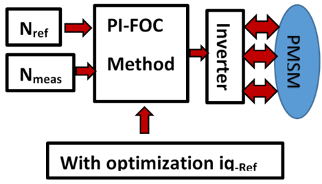
In the literature, several strategies are presented to solve the problem of energy management from multiple sources. We can cite the work of designing models identified online using the adaptive recursive least square method (ARLS) to search for a variation in FCS performance, with an optimization algorithm in order to find the best operating points for efficiency and power, using the Pontryagin’s minimum principle, for a FC-HEV [7]. An improved genetic algorithm (GA), is designed to optimize both the fuzzy rule base and the parameters of the membership functions, implemented for highway fuel economy certification test, the proposed approach is implemented in real time [8]. Works are presented, concerning strategies improving the efficiency of FC-HEV systems, as well as energy control, based on fuzzy logic techniques for FC / battery system, this control is well indicated, in terms of management of the exchanges of power between the FC, the battery and the solar PV system [9, 10]. Adaptive online optimization algorithms in an FCHEV are proposed, also, and a development of an energy management strategy is carried out, which is health conscious based on accurate estimation of degradation to improve the durability of the system [11-13]. Several adaptive algorithms and based on fuzzy logic are developed by the authors, by associating an operating mode control (OMC), with implementation of optimization of these strategies by offline simulation via a combined driving cycle [14-16]. There are more and more studies on strategies based on neural networks, and wavelet strategies, requiring more electronic equipment which increases the cost of HEV [17-19]. The proposed system is designed to meet power demands during the different phases of driving the vehicle. The objective is to make this system more efficient and reduce the consumption of hydrogen with an increase in the lifetime of the FC. This work proposes a new hybridization strategy of three sources (battery, FC and solar PV) with energy optimization, based on an AI algorithm, exploiting two blocks of parameters named PH and PO. Figure 1 shows the global scheme of the proposed HEV. This paper is organized as follows. Section 2 and 3 describe the models of FC system, solar PV, Battery, electric motor, vehicle’s dynamic, and the control of the different power converters used, the regulation of the speed and the voltage of the bus DC. Section 4 presents the proposed energy management strategy. Simulation results are presented and discussed in section 5. Finally, a conclusion is given in Section 6.
Figure 1. Global scheme of the FC/BATTERY/PV hybrid electric vehicle
Figure 1 shows an FC/PV/Battery configuration, which is the HEV model used in this work. In HEVs, electric traction is ensured by engines with sophisticated performance, such as small size, high power density, and high efficiency. Verifications are carried out on the type of permanent magnet motor model having feasibility for high torque density performance [20, 21]. This engine can achieve a wide speed range. Since the hybrid vehicle is non-linear and multivariable, the FLC model is more suitable for energy management [22].
2.1 Dynamic modeling of the PEMFC
The FC model used in this article is realized in MATLAB/Simulink. The relationship between the molar flow rate of hydrogen through the valve and its partial pressure inside the channel is expressed by relationship (1) [23].
$\frac{\mathrm{q}_{\mathrm{H}_{2}}}{\mathrm{P}_{\mathrm{H}_{2}}}=\frac{K_{a n}}{\sqrt{M_{H_{2}}}}=K_{H_{2}}$ (1)
Important factors constituting the molar flow rate of hydrogen are the hydrogen input rate, the hydrogen output rate and flow of hydrogen during the reaction [23]. Relationship (2) indicates these factors.
$\frac{d}{d t} P_{H_{2}}=\frac{R T}{V_{a n}}\left(q_{H_{2}}^{in}-q_{H_{2}}^{{out }}-q^r_{H_{2}}\right)$ (2)
The relationship (3) calculates the reacted hydrogen flow rate, and that according to the basic electrochemical relationship between the FC system flow and the hydrogen flow rate.
$q_{H_{2}}^{r}=\frac{N_{0} I_{F C}}{2 F}=2 K_{r} I_{F C}$ (3)
By applying the Laplace transformation, and Eqns. (1) and (3), the hydrogen partial pressure can be obtained according to reference
$P_{H_{2}}=\frac{1 / K_{H_{2}}}{1+\tau_{H_{2}} s}\left(q_{H_{2}}^{i n}-2 K_{r} I_{F C}\right)$ (4)
Or
$\tau_{H_{2}}=\frac{V_{a n}}{K_{H_{2}} R T}$ (5)
Similarly, the partial pressure of water and oxygen can be calculated. The polarization curve of the PEMFC is obtained from the sum of the Nernst voltage, the activation voltage, and the ohmic overvoltage. The expression (6) give the output voltage of FC while respecting the simplifying assumptions concerning the temperature and the oxygen concentration which are constant [24].
$V_{{cell}}=E+\eta_{ {act}}+\eta_{ {ohmic}}$ (6)
where, the activation voltage can be expressed as:
$\eta_{a c t}=-B \ln \left(C I_{F C}\right)$ (7)
And the ohmic overvoltage can be given by the following formula:
$\eta_{{ohmic}}=-R^{{int}} I_{F C}$ (8)
So, the formula (6) can be expressed as follow [24]:
$E=N_{0}\left[E_{0}+\frac{R T}{2 F} \log \left[\frac{P_{H_{2}} \sqrt{P_{o_{2}}}}{P_{H_{2} o}}\right]\right]$ (9)
The quantity of hydrogen available from the hydrogen reservoir is given by:
$q_{H_{2}}^{r e q}=\frac{N_{0} I_{F C}}{2 F U}$ (10)
The FC system produces the DC output voltage, depending on both the hydrogen and oxygen flow, and the configuration of the FC system [25]. The oxygen flow rate is determined according to the ratio $r_{H-O}$, representing the hydrogen-oxygen flow ratio [24].
2.2 Solar PV system modeling
As part of the simulation, we have modeled the solar PV system as well as Maximum power point tracking (MPPT) control in Matlab/Simulink environment [26]. The current-voltage characteristic of a PV array can be described as follows:
$I_{P V}=\eta_{p} I_{p h}-I_{r s}\left[\exp \left(\frac{q\left(V_{P V}+I_{P V} R_{S}\right)}{A K \eta_{S}}\right)-1\right]-\frac{V_{P V}}{R_{S h}}$ (11)
2.3 Battery modeling
In this section, the dynamic model of the lithium-ion battery is presented. The battery output voltage can be expressed as follows:
$V_{b a t}=V_{o c}-i_{b a t} Z_{e q}$ (12)
When there is no external load connected, the open circuit battery voltage is the electrical potential difference between its two terminals. The voltage of the battery in open circuit which depends on the SOC is calculated according to the formula below [27, 28]:
$V_{o c}\left(S O C_{b a t}\right)=-1,031 \times \exp \left(-35 \times S O C_{b a t}\right)+3,685+$$0,2156 \times S O C_{b a t}-0,1178 \times S O C_{b a t}^{2}+0,321 \times S O C_{b at}^{3}$ (13)
The SOC of battery can be expressed as:
$S O C_{b a t}=S O C_{b a t-i n i t}-\int \frac{i_{b a t}}{C_{b a t}} d t$ (14)
The equivalent internal impedance (Zeq) of the battery in Eq. (12) consists of a series resistor (Rseries) and two RC sub-circuits. The first is composed of a resistance RTransient_S mounted in parallel with a capacity CTransient_S, the same assembly for the second sub-circuit having a resistance RTransient_L connected in parallel with a capacity CTransient_L. The instantaneous voltage drop across the battery is due to the resistance Rseries effect. The components of the Resistance Capacity (RC) sub-circuits are responsible for the transient short and long-lasting regimes of the internal impedance of the battery. The values of Rseries, RTransient_S, CTransient_S, RTransient_L, and CTransient_L as a function of SOC of the battery can be calculated because of empirical equations obtained experimentally [27]. The lithium-ion battery model used in the hybrid system is designed in the Matlab/Simulink environment [29].
Figure 2 illustrates the dynamic model of the electrical vehicle carried out with SimDrive tool.
Figure 2. Dynamic model of the vehicle under SimDrive
This article deals with energy management in a FCEV. The proposed method is to find the best energy distribution between the three sources used: the PV, FC and the battery. The main objective is to minimize the hydrogen consumption by giving priority to the PV source and the battery, keeping the level of the charge state of the battery, in an optimal range. Exact calculation of PH and PO parameters is performed over overlapping regions to limit FC power and meet instantaneous energy demand.
3.1 Speed regulation
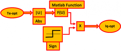
Figure 3 shows the internal block diagram of the PI regulator used. Due to the inertial property of the integrator, significant error can cause overruns [30]. Figure 4 shows optimization of the Iq reference current to gain system dynamics. In the PMSM command, we implemented an optimization algorithm for the current iq, illustrated in Figure 5.
Figure 3. Speed regulation
Figure 4. PI Controller with optimization
Figure 5. Simulink block of iq-ref current optimization
Eqns. (15) and (16) noted below, we provide the d-q components of the stator current.
$i_{q s}^{*}=\frac{2}{3} \frac{2}{p}\left(\frac{T_{e}^{*}}{\lambda_{r}^{*}}\right)\left(\frac{L_{r}}{L_{m}}\right)$ (15)
$i_{d s}^{*}=\frac{\lambda_{r}^{*}}{L_{m}}$ (16)
i*qs and i*ds are the components of the reference stator current, λ*r is the value of the rotor reference flux, and Lm is the mutual inductance, Lr is the rotor inductance and p is the number of pole pairs.
The expression of the angular speed is given by Eq. (17).
$\omega_{s}=\frac{L_{m} R_{r}}{L_{r} \lambda_{r}^{*}} i_{q s}^{*}$ (17)
$\phi_{d}=L_{d} I_{d}+\phi_{f}$ (18)
The rotor flux is generated along the axis q. The generated motor torque being proportional to the current iqs because the rotor flux of the axis d is constant according to Eq. (18), the maximum torque can be realized [31].
3.2 DC bus voltage regulation
The voltage across the DC-DC bus is controlled to a value approaching 500 volts. We have inserted a block of limitation of the voltage of the bus between two maximum and minimum values, in order to be able to transmit the surplus of power to the battery according to the value of the soc, if not towards a resistance. A signal will be generated to control the IGBT of the converter. The scheme of controlling the DC bus voltage is shown in Figure 6.
Figure 6. DC-DC bus voltage control
3.3 FC converter control
The fuel cell is controlled according to the requested power of the vehicle and according to the state of charge of the battery. The mode of hybridization of the three sources is taken into account in the design of this command of the FC. Thus, the FC will extend the autonomy of the vehicle and performance related to efficiency, while avoiding aging phenomena, to increase its life. The current should be limited in a slope so as to respect constraints related with FC dynamics.
The energy management subsystem determines the engine torque and the reference current of the fuel cell according to the predetermined parameters. The hybridization of energy sources in terms of power is managed according to the position of the accelerator, which varies between -1 and 1. Regenerative braking is designed during deceleration phases. The excess power of the fuel cell will be regulated via the two PH and PO blocks. The problem for the FC is at low speeds with high accelerations, leading to a decrease in its service life. The intelligent algorithm takes into account the faults of the classical algorithm used. The photovoltaic source intervenes during the shutdown phase to contribute to recharging the battery and also according to the parameters PH and PO during restart phases and degraded road conditions.
4.1 Energy management algorithm
The model is used in a detailed multi-domain simulation of a traction system for a dynamic fuel cell vehicle model combining a storage element that is a battery with a PV source. The use of Simulink blocks makes it possible to model accurately in a simulation environment, the electrical and mechanical blocs of the control subsystems. The fuel cell vehicle (FCV) is based on a recent topology used in commercial vehicles. The simulation model consists of three main modules. The electrical subsystem contains a PMSM. The EMS block of the system is shown in Figure 7.
Figure 7. Comparison between classical/AI algorithms
4.2 Implementation of fuzzy logic strategy
We propose to use fuzzy logic techniques in order to optimize power management in fuel cell system. The compatibility of our contribution with the FLC principle is the main argument of our choice vis-à-vis the other methods. The boundaries of membership functions are chosen taking into account the absolute need for FC intervention. As illustrated by Figure 8, we exploited the points in overlapping areas exploited in the FLC block, so that, at the end of the defuzzification process, we designed two PH and PO blocks in order to correct the data not processed by the fuzzy "black box" unit by comparing these results with predetermined references.
Figure 8. Detailed diagram of the AI algorithm design
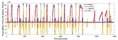
In this article, a numerical simulation was carried out using the Matlab / Simulink environment in order to show the performance of the proposed new method to optimize the energy management of hybrid FCEV. During high acceleration stage of the vehicle, the fuel cell provides energy for a large part of the required power as shown in Figure 9, with battery support, in response to a conventional algorithm embedded in an EMS block, providing acceptable results. Hydrogen consumption (Table 1) are greatly decreased with the association of the FC+B+PV configuration and AI algorithm.
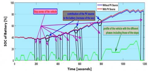
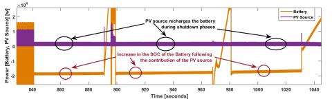
Figure 10 shows the power of the PV source where the performance of the system is considerably improved, in particular the autonomy of the vehicle and the reduction of the hydrogen consumption. The conventional used algorithm controls the battery in a way to assist the FC during the phases of high-power demands, and recharging the battery during the phases of stopping the vehicle. Important information on sources hybridization is given in Figure 11, and Figure 12. An increase in the battery soc is verified, thanks to the contribution of the PV source. A power gain in urban areas by multi-source hybridization and optimization of energy management in the study system are shown in Figure 13.
From the results in Figure 14, the hybridization power curves with FC+B+PV configuration can be seen. The load behaviour is optimized when using the AI algorithm, especially at low speeds. The power quality is improved and the efficiency of the FC is clearly improved. It is noted that the FC response to vehicle power demands is moderate compared to the results of the classical method.
Table 1. Comparison of results obtained with the methods: Classical (C) and artificial intelligence (AI)
|
Structure |
Hydrogen consumption [L] |
Stack consumption (Air; Fuel) [Standard lpm] for acceleration= 0,85 [m/s2] |
400 m Acceleration time [s] |
Stack efficiency at time 18 s [%] |
0 – 100 km/h Acceleration Time [s] |
|
FC+B (Classical Algorithm) |
2,17 |
797,32 – 1897,45 |
24,01 |
48,33 |
14,18 |
|
FC+B (AI Algorithm) |
1,79 |
731,66 –1891,11 |
23,79 |
57,78 |
13,36 |
|
FC+B+PV (Classical Algorithm) |
1,96 |
717,98 –1867,76 |
23,66 |
49,56 |
14,42 |
|
FC+B+PV (AI Algorithm) |
1,57 |
686,11 –1847,34 |
23,31 |
59,42 |
13,49 |
Figure 9. Power curves of FC + B hybrid vehicle
Figure 10. Power curves of FC+B+PV hybrid vehicle
Figure 11. Hybridization of sources - supply of the PV source for system
Figure 12. Hybridization of the PV source for optimization energy management of the multi-source system (increase of the soc)
Figure 13. Gain of power in urban areas by hybridization and optimization of the battery and the PV source
Figure 14. Power curves of FC + B + PV hybrid vehicle with AI algorithm
Figure 15. Optimization of energy management by avoiding any excess of FC
Figure 16. Power curves of the battery and the PV source after hybridization and optimization by the EMS block with the AI algorithm
Multi-source hybridization for an optimization of the energy management of these sources has been proposed as a solution for a problem related to the increase of the performances of a hybrid energy system for a power supply of an electric motor used in an application of electric vehicle. The concern was to increase the life of the FC as well as the economy of the hydrogen. The multi-source system uses renewable energy from a PV source, and an FC, as well as an energy storage device represented by a battery. A photovoltaic source can improve the storage device according to the characteristics of the vehicle applications and the main sources by providing an efficient hybridization associated with an optimal solution, implemented via an AI algorithm, in order to respond to changes in the phases, especially in urban areas, and when states of the road are degraded.
The main objective of this article is to provide a relevant solution to the question of increasing the autonomy, the effectiveness of the system, and especially the life of the FC, and to increase the economy in hydrogen. Also another objective has been achieved by raising the soc of the battery at a high rate despite the strong solicitations during the peak phases, by implementing a PV source. It should be noted also the good precision at times of power demands during the strong accelerations with introducing parameters PH and PO at the level of the intelligent algorithm by exploiting the point of strong accelerations with two blocks of hybridization and optimization to remove any excess power of the Fuel Cell. In the design of the parameters PH and PO, we took into consideration the state of a degraded road and the obstacles requiring acceleration of the vehicle in order to suppress the intervention of the FC, which has a significant time constant, resulting in a delay in response generating an excess of power.
In addition, a large reduction in the FC interventions is recognized, leading to an increase in its lifetime, resulting in a significant saving in hydrogen. The interest of this work lies in the dc-dc bus will be supplied directly from the B/PV device, as well as in the continuous recharging of the battery, especially during the stopping phases of the vehicle and during the regenerative braking.
|
A |
exponential zone amplitude, V |
|
|
B |
activation voltage constant, A−1 |
|
|
C |
activation voltage constant, V |
|
|
E |
nernst instantaneous voltage, V |
|
|
E0 |
standard no load voltage, V |
|
|
F |
faraday’s constant, C.kmol-1 |
|
|
IBAT-MEAS |
measured battery current, A |
|
|
IBAT-REF |
reference battery current, A |
|
|
icd, icq |
dq-axes iron losses current components, A |
|
|
id, iq |
the d-q stator current components, A |
|
|
IFC-REF1 |
fc current of flc output, A |
|
|
IFC-REF2 |
fc current of h-o bloc output, A |
|
|
imd, imq |
dq-axes magnetizing-current components, A |
|
|
IMOT-MEAS |
measured motor current, A |
|
|
IPV-MEAS |
measured pv source current, A |
|
|
iq-opt |
iq optimized in the foc block, A |
|
|
Irs |
cell reverse saturation current, A |
|
|
IΣ |
addition current of measured currents of battery and pv, A |
|
|
J |
moment of inertia, kg.m2 |
|
|
Kan |
anode valve constant, kmol.kg.atm.s-1 |
|
|
KH2 |
hydrogen valve molar constant, k.mol.atm.s-1 |
|
|
Kr |
modeling constant = No/4F, kmol s−1 A |
|
|
MH2 |
molar mass of hydrogen, kg.kmol-1 |
|
|
N0 |
number of series fuel cells in stack |
|
|
Nmeas |
motor’s measured speed, rd/s |
|
|
Nref |
motor reference speed, rd/s |
|
|
P*Batt |
Reference power of the battery, W |
|
|
PDEM |
requested power, W |
|
|
PFC-REF |
reference power of the fc, W |
|
|
PH2 |
partial pressure of hydrogen inside the stack, atm |
|
|
PH2O |
water partial pressure, atm |
|
|
PO2 |
partial pressure of oxygen inside the stack, atm |
|
|
P*recharge |
battery charging reference power, W |
|
|
q |
charge on an electron, C |
|
|
qH2 |
time derivative of ηH2, represents the hydrogen molar flow, k.mol.s-1 |
|
|
qH2in |
hydrogen input flow, k.mol.s-1 |
|
|
qH2out |
hydrogen output flow, k.mol.s-1 |
|
|
qH2r |
hydrogen flow that reacts, k.mol.s-1 |
|
|
qH2req |
amount of hydrogen flow required to meet load change, k.mol.s-1 |
|
|
Rint |
stack internal resistance, Ω |
|
|
R |
universal gas constant, J kmol−1 K |
|
|
s |
hydrogen time constant, s |
|
|
SOCbat |
state of charge of battery, % |
|
|
T |
absolute temperature, K |
|
|
Te-opt |
electromagnetic torque in the foc after optimization, N.m |
|
|
Van |
volume of anode, m3 |
|
|
Vbat |
voltage of battery, V |
|
|
Vcell |
voltage of fuel cell, V |
|
|
vd, vq |
dq-axes voltage components, V |
|
|
VDC_Meas |
measured voltage of the dc bus, V |
|
|
VDC_Ref |
reference voltage of the dc bus, V |
|
|
VFC_MEAS |
measured voltage of the fuel cell, V |
|
|
Vmpp |
voltage maximum power point, V |
|
|
Voc |
open-circuit voltage, V |
|
|
W_Motor |
motor speed, rd/s |
|
|
Greek symbols |
|
|
|
Φ |
perturbation introduced by the algorithm |
|
|
ηohmic |
function of stack current and the stack internal resistance Rint (Ω) |
|
|
ηact |
function of the oxygen concentration CO2 and stack current I (A) |
|
|
Subscripts |
|
|
|
Abs |
absolute |
|
|
AI |
artificial intelligence |
|
|
CTransient_L, CTransient_S |
rc parallel network capacities (l, s) of a model based on Thevenin |
|
|
EMS |
energy management strategy |
|
|
F |
membership function parameter indicating a low level |
|
|
FLC |
fuzzy logic controller |
|
|
FOC |
field oriented control |
|
|
M |
membership function parameter indicating an average level |
|
|
PH |
hybridization parameter |
|
|
PO |
optimization parameter |
|
|
Transient_S, RTransient_L |
rc parallel network resistors (l, s) of a model based on Thevenin |
|
|
np |
number of parallel strings in the pv array |
|
|
ns |
number of series strings in the pv array |
|
[1] Pina, A., Baptista, P., Silva, C., Ferrão, P. (2014). Energy reduction potential from the shift to electric vehicles: The Flores island case study. Energy Policy, 67: 37-47. http://dx.doi.org/10.1016/j.enpol.2013.07.120
[2] Yong, J.Y., Ramachandaramurthy, V.K., Tan, K.M., Mithulananthan, N. (2015). A review on the state-of-the-art technologies of electric vehicle, its impacts and prospects. Renewable and Sustainable Energy Reviews, 49: 365-385. https://doi.org/10.1016/j.rser.2015.04.130
[3] Wieczorek, M., Lewandowski, M. (2017). A mathematical representation of an energy management strategy for hybrid energy storage system in electric vehicle and real time optimization using a genetic algorithm. Applied Energy, 192: 222-233. https://doi.org/10.1016/j.apenergy.2017.02.022
[4] Wang, Y.F., Leung, D.Y.C., Xuan, J., Wang., H.Z. (2016). A review on unitized regenerative fuel cell technologies, part-a: Unitized regenerative proton exchange membrane fuel cells. Renewable and Sustainable Energy Reviews, 65: 961-977. https://doi.org/10.1016/j.rser.2016.07.046
[5] Alaswad, A., Baroutaji, A., Achour, H., Carton, J., Al Makky, A., Olabi, A.G. (2016). Developments in fuel cell technologies in the transport sector. International Journal of Hydrogen Energy, 41(37): 16499-16508. https://doi.org/10.1016/j.ijhydene.2016.03.164
[6] Wilberforce, T., El-Hassan, Z., Khatib, F.N., Al Makky, A., Baroutaji, A., Carton, J.G., Thompson, J., Olabi, A.G. (2017). Modelling and simulation of proton exchange membrane fuel cell with serpentine bipolar plate using MATLAB. International Journal of Hydrogen Energy, 42(40): 25639-25662. https://doi.org/10.1016/j.ijhydene.2017.06.091
[7] Ettihir, K., Boulon, L., Agbossou, K. (2016). Optimization-based energy management strategy for a fuel cell/battery hybrid power system. Applied Energy, 163: 142-153. https://doi.org/10.1016/j.apenergy.2015.10.176
[8] Zhang, R., Tao, J. (2018). GA-based fuzzy energy management system for FC/SC-powered HEV considering H2 consumption and load variation. IEEE Transactions on Fuzzy Systems, 26(4): 1833-1843. https://doi.org/10.1109/TFUZZ.2017.2779424
[9] Ettihir, K., Cano, H.M., Boulon, L., Agbossou, K. (2017). Design of an adaptive ems for fuel cell vehicles. International Journal of Hydrogen Energy, 42(2): 1481-1489. https://doi.org/10.1016/j.ijhydene.2016.07. 211
[10] Wai, R.J., Jhung, S.J., Liaw, J.J., Chang, Y.R. (2013). Intelligent optimal energy management system for hybrid power sources including fuel cell and battery. IEEE Transactions on Power Electronics, 28(7): 3231-3244. https://doi.org//10.1109/TPEL.2012.2219323.
[11] Zhou, D.M., Ravey, A., Al-Durra, A., Gao, F. (2017). A comparative study of extremum seeking methods applied to online energy management strategy of fuel cell hybrid electric vehicles. Energy Conversion and Management, 151: 778-790. https://doi.org/10.1016/j.enconman.2017.08.079
[12] Zhou, D.M., Al-Durra, A., Matraji, I., Ravey, A., Gao, F. (2018). Online energy management strategy of fuel cell hybrid electric vehicles: A fractional-order extremum seeking method. IEEE Transactions on Industrial Electronics, 65: 6787-6799. https://doi.org/10.1109/TIE.2018.2803723
[13] Yue, M.L., Jemei, S., Gouriveau, R., Zerhouni, N. (2019). Review on health-conscious energy management strategies for fuel cell hybrid electric vehicles: Degradation models and strategies. International Journal of Hydrogen Energy, 44(13): 6844-6861. https://doi.org/10.1016/j.ijhydene.2019.01.190
[14] Ahmadi, S., Bathaee, S.M.T. (2015). Multi-objective genetic optimization of the fuel cell hybrid vehicle supervisory system: Fuzzy logic and operating mode control strategies. International Journal of Hydrogen Energy, 40(36): 12512-12521. https://doi.org/10.1016/j.ijhydene.2015.06.160
[15] Carignano, M.G., Costa-Castelló, R., Roda, V., Nigro, N.M., Junco, S., Feroldi, D. (2017). Energy management strategy for fuel cell-supercapacitor hybrid vehicles based on prediction of energy demand. Journal of Power Sources, 360: 419-433. https://doi.org/10.1016/j.jpowsour.2017.06.016
[16] Wang, H., Huang, Y., Khajepour, A., Song, Q. (2016). Model predictive control-based energy management strategy for a series hybrid electric tracked vehicle. Applied Energy, 182: 105-114. https://doi.org/10.1016/j.apenergy.2016.08.085
[17] Munoz, P.M., Correa, G., Gaudiano, M.E., Fernandez, D. (2017). Energy management control design for fuel cell hybrid electric vehicles using neural networks. International Journal of Hydrogen Energy, 11: 28932-28944. https://doi.org/10.1016/j.ijhydene.2017.09.169
[18] Song, K., Li, F.Q., Hu, X., He, L., Niu, W.X., Lu, S.H., Zhang, T. (2018). Multi-mode energy management strategy for fuel cell electric vehicles based on driving pattern identification using learning vector quantization neural network algorithm. Journal of Power Sources, 389: 230-239. https://doi.org/10.1016/j.jpowsour.2018.04.024
[19] Ibrahim, M., Jemei, S., Wimmer, G., Yousfi Steiner, N., Kokonendji, C.C., Hissel, D. (2015). Selection of mother wavelet and decomposition level for energy management in electrical vehicles including a fuel cell. International Journal of Hydrogen Energy, 40: 15823-15833. https://doi.org/10.1016/j.ijhydene.2015.06.055
[20] Gao, G.W, Jin, Z.H., Zhang, J.Z., Li, J.Q., Ouyang, M. (2016). Development and performance analysis of a hybrid fuel cell/battery bus with an axle integrated electric motor drive system. International Journal of Hydrogen Energy, 41(2): 1161-1169. https://doi.org/10.1016/j.ijhydene.2015.10.046
[21] Bostanci, E., Moallem, M., Parsapour, A., Fahimi, B. (2017). Opportunities and challenges of switched reluctance motor drives for electric propulsion: A comparative study. IEEE Transactions on Transportation Electrification, 3: 58-75. https://doi.org/10.1109/TTE.2017.2649883
[22] Sulaiman, N., Hannan, M.A., Mohamed, A., Majlan, E.H., Wan Daud, W.R. (2015). A review on energy management system for fuel cell hybrid electric vehicle: Issues and challenges. Renewable and Sustainable Energy Reviews, 52: 802-814. https://doi.org/10.1016/j.rser.2015.07.132
[23] Lü, X.Q., Qu, Y., Wang, Y.D., Qin, C., Liu, G. (2018). A comprehensive review on hybrid power system for PEMFC-HEV: Issues and strategies. Energy Conversion and Management, 171: 1273-1291. https://doi.org/10.1016/j.enconman.2018.06.065
[24] Marzougui, H., Amari, M., Kadri, A., Bacha, F., Ghouili, J. (2017). Energy management of fuel cell/battery/ ultracapacitor in electrical hybrid vehicle. International Journal of Hydrogen Energy, 42: 8857-8869. https://doi.org/10.1016/j.ijhydene.2016.09.190
[25] Ettihir, K., Boulon, L., Agbossou, K. (2016). Energy management strategy for a fuel cell hybrid vehicle based on maximum efficiency and maximum power identification. IET Electrical Systems in Transportation, 6: 261-268. https://doi.org/10.1049/iet-est.2015.0023
[26] Krishna, S.K., Kumar, S.K. (2015). A review on hybrid renewable energy systems. Renewable and Sustainable Energy Reviews, 52: 907-916. https://doi.org/10.1016/j.rser.2015.07.187
[27] Kang, S., Zhao, L., Brouwer, J. (2019). Dynamic modeling and verification of a proton exchange membrane fuel cell-battery hybrid system to power servers in data centers. Renewable Energy, 143: 313-327. https://doi.org/10.1016/j.renene.2019.04.150
[28] Hannan, M.A., Lipu, M.S.H., Hussain, A., Mohamed, A. (2017). A review of lithium-ion battery state of charge estimation and management system in electric vehicle applications: Challenges and recommendations. Renewable and Sustainable Energy Reviews, 78: 834-854. https://doi.org/10.1016/j.rser.2017.05.001
[29] Alegre, S., Míguez, J.V., Carpio, J. (2017). Modelling of electric and parallel-hybrid electric vehicle using Matlab/Simulink environment and planning of charging stations through a geographic information system and genetic algorithms. Renewable and Sustainable Energy Reviews, 74: 1020-1027. https://doi.org/10.1016/j.rser.2017.03.041
[30] Marzougui, H., Amari, M., Kadri, A., Bacha, F., Ghouili, J. (2017). Energy management of fuel cell/battery/ultracapacitor in electrical hybrid vehicle. International Journal of Hydrogen Energy, 42: 8857-8869. https://doi.org/10.1016/j.ijhydene.2016.09.190
[31] Fathabadi, H. (2018). Fuel cell hybrid electric vehicle (FCHEV): Novel fuel cell/SC hybrid power generation system. Energy Conversion and Management, 156: 192-201. https://doi.org/10.1016/j.enconman.2017.11.001