Fei Deng | Xiaoyang Liu | Nuo Zhang | Fuxiang Zhang*
OPEN ACCESS
This paper proposes a novel 3T2R labelling robot with hybrid mechanism for the end-faces of round steels. The hybrid mechanism consists of a three degrees-of-freedom (DOFs) translation (3T) parallel mechanism and a two DOFs rotation (2R) mechanism. Based on the Jacobian matrix of the hybrid mechanism, the author analyzed the influence of each dimension parameter on three performance indices, namely, kinematics, transmission and stiffness of the mechanism, under the constraints of the workspace. Based on the Pareto frontier approach, the Non-dominated Sorting Genetic Algorithm II (NSGA-II) was adopted to find the optimal values of the three performance indices, and identify the dimension parameters that bring the best overall performance of the whole mechanism. The research results shed new light on the design of light weight labelling robot.
hybrid mechanism, dimension synthesis, Jacobian matrix, pareto frontier approach, multi-objective optimization
In recent years, automatic labelling is increasingly adopted for steel products [1, 2]. The effect and efficiency of the labelling robot directly hinge on the labelling mechanism. For the end-face of round steel, the labelling mechanism should have fast speed and a large workspace. Compared with parallel or series mechanism, the hybrid mechanism is suitable for end-face labelling of round steel, thanks to its fast speed, high precision, flexibility and large workspace [3, 4]. Therefore, more attention should be paid to this type of mechanism in future [5, 6].
Dimension synthesis is an important aspect of the design of labelling robot [7, 8]. The performance of a labelling robot with hybrid mechanism varies greatly with its dimensions [9, 10]. Good dimension parameters can give full play to the advantages of the hybrid mechanism, and facilitate the dimension synthesis of the robot. The most popular ways for dimension synthesis include the performance atlas method and the objective function method [11, 12]. The former approach uses graphics to express performance indices and their relationship with dimension parameters, and then reduces the number of these parameters. This approach is simple and intuitive, but does not consider the operability or other indices of the labelling mechanism. The objective function method is a machine-based method established according to the structure and work requirements. By this method, the dimension parameters are optimized using an optimization algorithm. Currently, there is little report on the dimension synthesis of labelling robots with hybrid mechanism, not to mention that of 3T2R labeling robot [13-16].
To make up for the gap, this paper configures a novel 3T2R labelling robot with hybrid mechanism and optimizes its dimension parameters, according to the requirements on end-face labelling of round steel. First, the hybrid mechanism was set up based on a three degrees-of-freedom (DOFs) translation (3T) parallel mechanism and a two DOFs rotation (2R) mechanism. Next, the author analyzed the influence of each dimension parameter on several performance indices of the hybrid mechanism. Finally, the dimension parameters were optimized by the Non-dominated Sorting Genetic Algorithm II (NSGA-II), based on the Pareto frontier approach.
In steel mills, the round steels have a diameter between 40 mm and 70 mm and a length of 4~12 m. The total diameter of a bundle of round steels is generally smaller than 360 mm. The total weight of the bundle is roughly 2.5 t. Before end-face labelling, the round steels need to be place horizontally at a maximum interval of 50 mm.
During automatic labelling, the labelling mechanism must attach the label vertically to the end-face of each round steel. Hence, the end effector of the mechanism should be able to translate in the three directions of the workspace and also rotate freely to attach the label onto the end-face vertically.
In the light of the above, this paper proposes a 3T2R labelling robot with hybrid mechanism [17]. The hybrid mechanism is composed of a 3T parallel mechanism with a 2R rotation mechanism. As shown in Figure 1, the entire robot is built on the basis of a static platform. Between the moving and static platforms lies the 3T parallel mechanism with three parallel branches. An industrial camera and a ring array light source are arranged at the middle of the moving platform to visually recognize round steels. The series robotic arm, i.e. the 2R rotation mechanism, is mounted on the moving platform. The 2R rotation mechanism has two joints connected in series to the moving platform above the parallel mechanism. The axes of the two joints are perpendicular to each other. The end effector for end-face labelling is installed at the end of the series robotic arm.
1. Static platform, 2. Parallel branches, 3 Moving platform, 4 Ring array light source, 5. Industrial camera, 6. Series robotic arm, 7. End effector
Figure 1. The structure of the labelling robot with hybrid mechanism
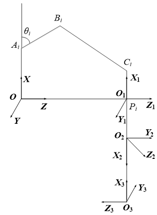
The hybrid mechanism is detailed in Figure 2, where O-XYZ is the base coordinate system established at the center of the static platform, O1-X1Y1Z1 is the coordinate system established at the center of the moving platform, O2-X2Y2Z2 is the coordinate system established at the first joint of the rotation mechanism, O3-X3Y3Z3 is the coordinate system established at the second joint of the rotation mechanism.
The other parameters of the hybrid mechanism are defined as follows: the radius of the static platform, R; the radius of the moving platform, r; the length of the active arm, L; the length of the slave arm, l; the opening angle of the active arm, θ; the angle of the X axis of O-XYZ, φ; the length of the first joint, a1; the length of the second joint, a2.
Figure 2. The hybrid mechanism
The Jacobian matrix of the hybrid robot represents the mapping relationship between the joints and the end effector. Solving the matrix accurately lays the basis for analyzing the speed, static, flexibility, singularity and operability of the robot [18, 19]. So far, many scholars have explored the Jacobian matrix of the series mechanism or the parallel mechanism, and achieved fruitful results. However, the research on the Jacobian matrix of hybrid mechanism is extremely scarce. To build the Jacobian matrix of our robot, the first step is to clarify the coordinate systems of its hybrid mechanism (Figure 3).
Figure 3. The coordinate systems of the hybrid mechanism
As mentioned before, the hybrid mechanism in our robot consists of a 3T parallel mechanism and a 2R rotation mechanism, which is essentially a series mechanism. The Jacobian matrix of the parallel mechanism can be obtained by deriving its kinematic constraint equation through differential transform. The single-branch constraint of the parallel mechanism can be expressed as:
OPi=OAi+AiBi+BiCi+CiPi. (1)
Finding the derivation relative to time t at both sides of formula (1), the velocity vector VP=[vx,vy,vz]T of point P in O-XYZ can be obtained as:
VP=ωi1×ai+ωi2×bi. (2)
where, ai=AiBi; bi=AiBi; ωij (i=1,2,3; j=1,2) is the angular velocity vector of the j-th member of branch i.
Multiplying both sides of formula (2) by bi, we have:
VP·bi =ωi1×ai·bi. (3)
where, the vectors in O-XYZ can be expressed as:
${{a}_{i}}={{l}_{2}}\left[ \begin{matrix} \cos {{\theta }_{i1}} \\ 0 \\ \sin {{\theta }_{i1}} \\\end{matrix} \right]$, ${{b}_{i}}={{l}_{1}}\left[ \begin{matrix} \sin {{\theta }_{i3}}\cos \left( {{\theta }_{i1}}+{{\theta }_{i2}} \right) \\ \cos {{\theta }_{i3}} \\ \sin {{\theta }_{i3}}\sin \left( {{\theta }_{i1}}+{{\theta }_{i2}} \right) \\\end{matrix} \right]$, ${{\omega }_{i1}}={{l}_{2}}\left[ \begin{matrix} 0 \\ -{{{\dot{\theta }}}_{i1}} \\ \sin {{\theta }_{i1}} \\\end{matrix} \right]$.
Let p=OP=[x,y,z]T. Then, then p in O-XYZ can be expressed as:
${}_{O}^{{{O}_{i}}}R=\left[ \begin{matrix} \cos {{\varphi }_{i}} & \sin {{\varphi }_{i}} & 0 \\ -\sin {{\varphi }_{i}} & \cos {{\varphi }_{i}} & 0 \\ 0 & 0 & 1 \\\end{matrix} \right]$. (4)
where,
${}_{O}^{{{O}_{i}}}R=\left[ \begin{matrix} \cos {{\varphi }_{i}} & \sin {{\varphi }_{i}} & 0 \\ -\sin {{\varphi }_{i}} & \cos {{\varphi }_{i}} & 0 \\ 0 & 0 & 1 \\\end{matrix} \right]$ is the rotation matrix between the static from O-XYZ to Oi-XiYiZi; ${}^{{{O}_{i}}}{{p}_{O}}={{\left[ -R,0,0 \right]}^{\text{T}}}$ is the position vector of the point P in Oi-XiYiZi.
Finding the derivation relative to time t at both sides of formula (4), the velocity vector of point P in Oi-XiYiZi can be obtained as:
${{\left[ {{v}_{p}} \right]}_{{{O}_{i}}}}={}_{O}^{{{O}_{i}}}R\left[ \begin{matrix} {\dot{x}} \\ {\dot{y}} \\ {\dot{z}} \\\end{matrix} \right]=\left[ \begin{matrix} {{v}_{x}}\cos {{\varphi }_{i}}+{{v}_{y}}\sin {{\varphi }_{i}} \\ -{{v}_{x}}\sin {{\varphi }_{i}}+{{v}_{y}}\cos {{\varphi }_{i}} \\ {{v}_{z}} \\\end{matrix} \right]$.
Substituting ai, bi and ωij into formula (3), we have:
Ji1vx+ji2vy+ji3vz=kiθi1 (i=1,2,3). (5)
where,
ji1=cos(θi1+θi2)sinθi3cosφi-cosθi3sinφi;
ji2=cos(θi1+θi2)sinθi3sinφi+cosθi3cosφi;
ji3=sin(θi1+θi2)sinθi3; ki=l1sinθi2sinθi3.
Substituting i=1, 2 and 3 into the above formulas, the results can be written as the matrix below:
${{J}_{Q}}{{V}_{P}}={{J}_{q}}\dot{q}$Ji1vx+ji2vy+ji3vz=kiθi1 (i=1,2,3). (6)
where,
${{J}_{Q}}=\left[ \begin{matrix} {{j}_{11}} & {{j}_{12}} & {{j}_{13}} \\ {{j}_{21}} & {{j}_{22}} & {{j}_{23}} \\ {{j}_{31}} & {{j}_{32}} & {{j}_{33}} \\\end{matrix} \right]$, ${{J}_{q}}=\left[ \begin{matrix} {{k}_{1}} & 0 & 0 \\ 0 & {{k}_{2}} & 0 \\ 0 & 0 & {{k}_{3}} \\\end{matrix} \right]$,
$\dot{q}={{\left[ {{\theta }_{11}},{{\theta }_{21}},{{\theta }_{31}} \right]}^{\text{T}}}$ are the forward Jacobian matrix, the inverse Jacobian matrix and the angular velocity matrix of the three branches of the active arm.
The Jacobian matrix JP of the parallel mechanism can be expressed as:
${{J}_{P}}=J_{Q}^{-1}{{J}_{q}}=\left[ \begin{matrix} {{J}_{11}} & {{J}_{12}} & {{J}_{13}} \\ {{J}_{21}} & {{J}_{22}} & {{J}_{23}} \\ {{J}_{31}} & {{J}_{32}} & {{J}_{33}} \\\end{matrix} \right]$. (7)
In the O-XYZ, the Denavit–Hartenberg (D-H) parameter of the hybrid mechanism reflects the coordinate conversion relationship of adjacent joints [20, 21]. The geometric center of the moving platform is taken as the origin of the O1-X1Y1Z1. According to the transform matrix of each branch to the end of the A transform matrix [22], we have:
${}^{0}{{A}_{n}}={}^{0}{{A}_{1}}{}^{1}{{A}_{n}}=\left[ \begin{matrix} {{n}_{x}} & {{o}_{x}} & {{a}_{x}} & {{p}_{x}} \\ {{n}_{y}} & {{o}_{y}} & {{a}_{y}} & {{p}_{y}} \\ {{n}_{z}} & {{o}_{z}} & {{a}_{z}} & {{p}_{z}} \\ 0 & 0 & 0 & 1 \\\end{matrix} \right]=\left[ \begin{matrix} R & P \\ 0 & 1 \\\end{matrix} \right]$. (8)
where, iAi+1 is the transform matrix of two adjacent coordinate systems; R is the attitude matrix; P is the position vector. According to the homogeneous transform matrix, we have:
${}^{1}{{A}_{2}}=\left[ \begin{matrix} {{\text{c}}_{4}} & 0 & {{\text{s}}_{4}} & {{l}_{3}}{{\text{c}}_{4}} \\ {{\text{s}}_{4}} & 0 & -{{\text{c}}_{4}} & {{l}_{3}}{{\text{s}}_{4}} \\ 0 & 1 & 0 & 0 \\ 0 & 0 & 0 & 1 \\\end{matrix} \right]$, ${}^{2}{{A}_{3}}=\left[ \begin{matrix} {{\text{c}}_{5}} & 0 & -{{\text{s}}_{4}} & {{l}_{4}}{{\text{c}}_{5}} \\ {{\text{s}}_{5}} & 0 & {{\text{c}}_{5}} & {{l}_{4}}{{\text{s}}_{5}} \\ 0 & -1 & 0 & 0 \\ 0 & 0 & 0 & 1 \\\end{matrix} \right]$, ${}^{1}{{A}_{3}}={}^{1}{{A}_{2}}{}^{2}{{A}_{3}}=\left[ \begin{matrix} {{\text{c}}_{4}}{{\text{c}}_{5}} & -{{\text{s}}_{4}} & -{{\text{c}}_{4}}{{\text{s}}_{4}} & {{l}_{3}}{{\text{c}}_{4}}+{{l}_{4}}{{\text{c}}_{4}}{{\text{c}}_{5}} \\ {{\text{c}}_{5}}{{\text{s}}_{4}} & {{\text{c}}_{4}} & -{{\text{s}}_{4}}{{\text{s}}_{5}} & {{l}_{3}}{{\text{s}}_{4}}+{{l}_{4}}{{\text{c}}_{5}}{{\text{s}}_{4}} \\ {{\text{s}}_{5}} & 0 & {{\text{c}}_{4}} & {{l}_{4}}{{\text{s}}_{5}} \\ 0 & 0 & 0 & 1 \\\end{matrix} \right]$.
The differential transform was adopted to solve the Jacobian matrix J of hybrid mechanism. For a moving branch i, there exists: Ji=[nz oz az 0 0 0]T.
For a rotating joint i, there exists:
${{J}_{i}}=\left[ \begin{matrix} {{\left( p\times n \right)}_{z}} \\ {{\left( p\times o \right)}_{z}} \\ {{\left( p\times a \right)}_{z}} \\ {{n}_{z}} \\ {{o}_{z}} \\ {{a}_{z}} \\\end{matrix} \right]=\left[ \begin{matrix} -{{n}_{x}}{{p}_{y}}+{{n}_{y}}{{p}_{x}} \\ -{{o}_{x}}{{p}_{y}}+{{o}_{y}}{{p}_{x}} \\ -{{a}_{x}}{{p}_{y}}+{{a}_{y}}{{p}_{x}} \\ {{n}_{z}} \\ {{o}_{z}} \\ {{a}_{z}} \\\end{matrix} \right]$. (9)
The Jacobian matrix JS of the rotation mechanism can be obtained as:
${{J}_{S}}=\left[ \begin{matrix} 0 & {{l}_{3}}\text{c}_{5}^{2}+{{l}_{4}}{{\text{s}}_{4}}{{\text{s}}_{5}} \\ 0 & -{{l}_{3}}\text{c}_{4}^{2}{{\text{s}}_{4}} \\ 0 & -{{l}_{4}}{{\text{c}}_{4}}{{\text{s}}_{5}} \\ -{{c}_{4}}{{\text{s}}_{4}} & {{\text{s}}_{4}} \\ -{{\text{s}}_{4}}{{\text{s}}_{5}} & -{{\text{c}}_{4}} \\ {{\text{c}}_{4}} & 0 \\\end{matrix} \right]$. (10)
Considering the structural features of the labeling robot, the parallel mechanism was viewed as a joint and the hybrid mechanism as a series structure between the parallel mechanism and the rotation (series) mechanism. During the differential transform, both the Jacobian matrices of the parallel mechanism and that of the rotation mechanism were solved column by column. The position information of the robot structure was substituted into the corresponding columns of the two matrices. Then, the two matrices were combined into the Jacobian matrix of the hybrid mechanism J:
$J=\left[ \begin{matrix} {{J}_{11}} & {{J}_{12}} & {{J}_{13}} & 0 & {{l}_{3}}\text{c}_{4}^{2}+{{l}_{4}}{{\text{s}}_{4}}{{\text{s}}_{5}} \\ {{J}_{21}} & {{J}_{22}} & {{J}_{23}} & 0 & -{{l}_{3}}\text{c}_{4}^{2}{{s}_{4}} \\ {{J}_{31}} & {{J}_{32}} & {{J}_{33}} & 0 & -{{l}_{4}}{{\text{c}}_{4}}{{\text{s}}_{5}} \\ 0 & 0 & 0 & -{{\text{c}}_{4}}{{\text{s}}_{4}} & {{\text{s}}_{4}} \\ 0 & 0 & 0 & -{{\text{s}}_{4}}{{\text{s}}_{5}} & -{{\text{c}}_{4}} \\ 0 & 0 & 0 & {{\text{c}}_{4}} & 0 \\\end{matrix} \right]$. (11)
The kinematics performance directly bears on the labelling effect of the robot. The condition number KJ of the Jacobian matrix of the hybrid mechanism was used to measure this performance index [23]. If the condition number is infinite, the Jacobian matrix of the hybrid mechanism is singular. The number of conditions varies with the robot configurations, and the minimum value is 1. If KJ=1, the hybrid mechanism has the best kinematics performance. Therefore, the optimization goal of the kinematic performance was set to: KJ→min, where KJ is Jacobian matrix of the hybrid mechanism. The ratio of the maximum singular value σmax(J) to the minimum singular value σmax(J) can be defined as:
${{K}_{J}}=\left\| J \right\|\cdot \left\| {{J}^{\text{-1}}} \right\|\text{=}\frac{{{\sigma }_{\max }}\left( J \right)}{{{\sigma }_{\min }}\left( J \right)}$. (12)
where, ||J|| is a 2-norm of J. This norm can be rewritten as a Frobenius norm:
$\left\| J \right\|={{\left( \sum\limits_{i,j=1}^{n}{{{a}_{ij}}^{2}} \right)}^{1/2}}$. (13)
Considering the spatial changes of kinematics, the global kinematic performance index f1(l) was introduced to the robot workspace W [24, 25]:
${{f}_{1}}\left( l \right)=\frac{\int\limits_{w}{{{K}_{J}}dw}}{\int\limits_{w}{dw}}\to \min $. (14)
The stiffness of the robot also greatly affects the labelling effect of the hybrid mechanism. Hence, the global stiffness performance index f2(l) was defined to optimize the stiffness of the hybrid mechanism. The stiffness of the hybrid mechanism can be represented as:
$G\text{=}k{{J}^{\text{T}}}J$. (15)
where, k=1 is the stiffness coefficient; JTJ is the eigenvalue of the matrix, which corresponds to the maximum stiffness. Therefore, the optimization goal of the stiffness performance is to maximize the stiffness. This objective can be expressed as the reverse function below:
x${{\lambda }_{\min }}\left( {{J}^{\text{T}}}J \right)={{\left( {{\sigma }_{\min }} \right)}^{2}}\to \max \Leftrightarrow {{K}_{G}}\to \min $.
where, KG=||G||·||G-1||. ||G|| is a 2-norm of G. This norm can be rewritten as a Frobenius norm [26]:
$\left\| G \right\|={{\left( \sum\limits_{i,j=1}^{n}{{{a}_{ij}}^{2}} \right)}^{1/2}}$. (16)
Considering the spatial changes of stiffness, the global stiffness performance index f2(l) was introduced to the robot workspace W:
${{f}_{2}}\left( l \right)=\frac{\int\limits_{w}{{{K}_{G}}dw}}{\int\limits_{w}{dw}}\to \min $. (17)
In addition, the reciprocal of the global condition number was taken as the evaluation criterion for the transmission performance of the hybrid mechanism. The greater the reciprocal, the better the transmission performance. Hence, the negative number of the global condition number was treated as the global transmission performance index function f3(l):
${{f}_{3}}\left( l \right)=-\frac{\int\limits_{w}{\text{1/}{{K}_{J}}dw}}{\int\limits_{w}{dw}}\to \min $. (18)
First, the dimension parameters to be optimized were determined, including length of the active arm l1, the length of the slave arm l2, the radius difference between the static and moving platforms l3, the length of the first joint l4, and the length of the second joint l5. The dimension synthesis aims to find a vector P=[l1l2l3l4l5]T that optimizes the overall performance of the hybrid mechanism. Note that there may be contradictions between the optimizations of different dimension parameters, that is, optimizing one parameter might cause another parameter to deteriotate. Therefore, the dimension synthesis should stirke a balance between these parameters to optimize the overall performance. The multi-objective optimization problem can be modelled as:
$\begin{align} & V-\min f\left( x \right)=\min \left[ {{f}_{1}}\left( x \right),{{f}_{2}}\left( x \right),{{f}_{3}}\left( x \right) \right] \\ & \begin{matrix} \text{s}\text{.t}. & {{l}_{1}}_{\min }\le {{l}_{1}}\le {{l}_{1\max }} \\\end{matrix} \\ & \ \ \ \ \ \ \ {{l}_{2}}_{\min }\le {{l}_{2}}\le {{l}_{2\max }} \\ & \ \ \ \ \ \ \ {{l}_{3}}_{\min }\le {{l}_{3}}\le {{l}_{3\max }} \\ & \ \ \ \ \ \ \ {{l}_{4}}_{\min }\le {{l}_{4}}\le {{l}_{4\max }} \\ & \ \ \ \ \ \ \ {{l}_{5\min }}\le {{l}_{5}}\le {{l}_{5\max }} \\ \end{align}$.
It is difficult to find the parallel mechanism or the reverse mechanism of the series mechanism. Therefore, it is unlikely to fund a unified function to express the positive or negative solution of the hybrid mechanism. The objective function of the above model contains the end position information of both parallel and series mechanisms, which are related to that of the hybrid mechanism. The dimension parameters cannot be unified easily.
To overcome the above difficulties, the kinematics inverse solution of the parallel mechanism was obtained to determine the end position information of that mechanism. This information was saved on the Matlab. The end position information of the series mechanism was obtained by the Monte-Carlo method. On this basis, the end position information of the hybrid information was fitted by the Matlab.
Each of the three performance indices has an extremely complex function. Traditionally, the optimization strategy is to weight each objective function, or convert several objective functions into a single-objective function. In this paper, the NSGA-II, which is based on the Pareto frontier approach, is introduced to optimize the dimension parameters of the hybrid mechanism, using the elite retention strategy. This algorithm can reduce the complexity and ensure the diversity of the pareto solution.
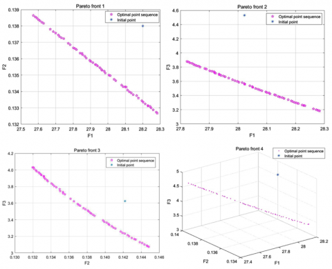
According to the designed robot, the constraints of our optimization problem are 150≤l1≤300, 300≤l2≤600. 30≤l3≤100, 50≤l4≤80 and 50≤l5≤80. The Pareto fronts of the multi-objective optimization are illustrated in Figure 4 below.
The optimized vector can be obtained as P=[231.97 577.68 76.326 76.868 69.754]T. In other words, the optimal results of the multi-objective optimization problem are l1=232.2749, l2=577.6572, l3=76.9924, l4=76.8491 and l5=68.3872. For applicability, the results were rounded to l1=230, l2=580, l3=77, l4=77 and l5=70. Then, each component of the hybrid mechanism was modified according to the results.
Table 1 compares the kinematics performance, stiffness performance and transmission performance before and after the optimization. It can be seen that, after parameter synthesis, the performance indices were improved across the board. The kinematics performance of the mechanism was improved by 1.32%, the stiffness performance by 5.07%, and the transmission performance by 20.61%.
Figure 4. Pareto fronts of the multi-objective optimization
Table 1. Performance comparison before and after dimension synthesis
|
|
Kinematics performance |
Stiffness performance |
Transmission performance |
|
Before optimization |
28.02 |
0.138 |
4.56 |
|
After optimization |
27.65 |
0.131 |
3.62 |
|
Performance improvement |
1.32% |
5.07 % |
20.61% |
This paper explores deep into the dimension synthesis of hybrid labelling mechanism for end-face of round steels. The hybrid mechanism was viewed as a series mechanism, with the parallel mechanism as a joint. In this way, the Jacobian matrix of the hybrid mechanism was obtained, and then the dimension synthesis was completed.
The dimension synthesis was treated as a multi-objective optimization problem. The objective function was optimized, and its parameters were unified by the inverse solution of the parallel mechanism and the variable of the rotation (series) mechanism obtained by the Monte-Carlo method. The optimal value of the multi-objective function was obtained by the NSGA-II based on the Pareto frontier approach.
Then, the hybrid mechanism was modified based on the optimization results. The comparison shows that the kinematics performance of the mechanism was improved by 1.32%, the stiffness performance by 5.07%, and the transmission performance by 20.61%. Through the dimension synthesis, the author obtained the suitable dimension parameters of the labelling robot, improved the speed and stability of labelling, and reduced the power consumption. The research results provide a valuable guide for the design and application of labelling robots.
This work is financially supported by National Key R & D Program of China (2018YFB1308700), Hebei Province Science and Technology Major Special Project (19011826Z), Hebei Province Natural Science Foundation (E2017208111), and Hebei University of Science and Technology Scientific Research Fund.
[1] Bulgarevich, D.S., Tsukamoto, S., Kasuya, T., Demura, M., Watanabe, M. (2019). Automatic steel labeling on certain microstructural constituents with image processing and machine learning tools. Science and technology of advanced materials, 20(1): 532-542. http://dx.doi.org/10.1080/14686996.2019.1610668
[2] Zhang, F., Cai, L., Li, W., Huang, F. (2016). Design of automatic labeling system on the end surfaces of bundles of round steels. Journal of Hebei University of Science and Technology, 37(6): 601-608. http://doi.org/10.7535/hbkd.2016yx06012
[3] Li, Y., Sato, H. (2018). Insect-computer hybrid robot. Molecular Frontiers Journal, 2(1): 30-42. http://dx.doi.org/10.1142/S2529732518500025
[4] Petko, M., Gac, K., Góra, G., Karpiel, G., Ochoński, J., Kobus, K. (2016). CNC system of the 5-axis hybrid robot for milling. Mechatronics, 37: 89-99. http://dx.doi.org/10.1016/j.mechatronics.2016.03.001
[5] Wen, K., Gosselin, C. (2019). Kinematically redundant hybrid robots with simple singularity conditions and analytical inverse kinematic solutions. IEEE Robotics and Automation Letters, 4(4): 3828-3835. http://dx.doi.org/10.1109/LRA.2019.2928756
[6] Fajardo-Pruna, M., López-Estrada, L., Pérez, H., Diez, E., Vizán, A. (2019). Analysis of a single-edge micro cutting process in a hybrid parallel-serial machine tool. International Journal of Mechanical Sciences, 151: 222-235. http://dx.doi.org/10.1016/j.ijmecsci.2018.11.023
[7] Moosavian, A., Zhu John Sun, C., Inman, D.J. (2017). Dimensional synthesis of a multiloop linkage with single input using parameterized curves. Journal of Mechanisms and Robotics, 9(2): 1-25. http://dx.doi.org/10.1115/1.4035799
[8] Martínez, S., Rueda, M., Martínez, H., Arcos, A. (2017). Optimal dimension and optimal auxiliary vector to construct calibration estimators of the distribution function. Journal of Computational and Applied Mathematics, 318: 444-459. https://doi.org/10.1016/j.cam.2016.02.002
[9] Petko, M., Karpiel, G., Gac, K., Góra, G., Kobus, K., Ochoński, J. (2016). Trajectory tracking controller of the hybrid robot for milling. Mechatronics, 37: 100-111. http://dx.doi.org/10.1016/j.mechatronics.2016.03.012
[10] Mariolo, A.V., Casiraghi, M., Galetta, D., Spaggiari, L. (2018). Robotic hybrid approach for an anterior pancoast tumor in a severely obese patient. The Annals of Thoracic Surgery, 106(3): e115-e116. https://doi.org/10.1016/j.mechatronics.2016.03.012
[11] Préault, C., Saafi, H., Laribi, M.A., Zeghloul, S. (2019). Optimal design and evaluation of a dexterous 4 DoFs haptic device based on delta architecture. Robotica, 37(7): 1267-1288. https://doi.org/10.1017/S0263574718000929
[12] Ilyushin, Y.V., Pervukhin, D.A., Afanasieva, O.V., Afanasyev, M.P., Kolesnichenko, S.V. (2015). The methods of the synthesis of the nonlinear regulators for the distributed one-dimension control objects. Modern Applied Science, 9(2): 54-67. http://dx.doi.org/10.5539/mas.v9n2p42
[13] Saadatzi, M.H., Masouleh, M.T., Taghirad, H.D. (2012). Workspace analysis of 5-PRUR parallel mechanisms (3T2R). Robotics and Computer-Integrated Manufacturing, 28(3): 437-448. http://dx.doi.org/10.1016/j.rcim.2011.12.002
[14] Schappler, M., Tappe, S., Ortmaier, T. (2019). Modeling Parallel robot kinematics for 3T2R and 3T3R tasks using reciprocal sets of Euler angles. Robotics, 8(3): 68-92. http://dx.doi.org/10.3390/robotics8030068
[15] Schappler, M., Tappe, S., Ortmaier, T. (2019). Resolution of functional redundancy for 3T2R robot tasks using two sets of reciprocal Euler angles. In IFToMM World Congress on Mechanism and Machine Science, 1701-1710. http://dx.doi.org/10.1007/978-3-030-20131-9_168
[16] Amine, S., Masouleh, M.T., Caro, S., Wenger, P., Gosselin, C. (2012). Singularity analysis of 3T2R parallel mechanisms using Grassmann-Cayley algebra and Grassmann geometry. Mechanism and Machine Theory, 52: 326-340. http://dx.doi.org/10.1016/j.mechmachtheory.2011.11.015
[17] Chang, T.H., Chen, S.L., Kang, C.A., Inasaki, I. (2002). Design optimization of the linkage dimension for a hybrid-type parallel kinematic machine tool. Proceedings of the Institution of Mechanical Engineers, Part K: Journal of Multi-body Dynamics, 216(2): 143-156. http://dx.doi.org/10.1243/14644190260070385
[18] Chen, D., Zhang, Y., Li, S. (2017). Tracking control of robot manipulators with unknown models: A Jacobian-matrix-adaption method. IEEE Transactions on Industrial Informatics, 14(7): 3044-3053. http://dx.doi.org/10.1109/TII.2017.2766455
[19] Crisan, A., Negrean, I. (2019). The Jacobian matrix based on the transfer matrices. ACTA Technica Napocensis-Series: Applied Mathematics, Mechanics, and Engineering, 62(1): 135-140.
[20] Wu, L., Crawford, R., Roberts, J. (2017). An analytic approach to converting POE parameters into D-H parameters for serial-link robots. IEEE Robotics and Automation Letters, 2(4): 2174-2179. http://dx.doi.org/10.1109/LRA.2017.2723470
[21] Singh, A., Singla, A., Soni, S. (2015). Extension of DH parameter method to hybrid manipulators used in robot-assisted surgery. Proceedings of the Institution of Mechanical Engineers, Part H: Journal of Engineering in Medicine, 229(10): 703-712. https://doi.org/10.1177/0954411915602289
[22] Safeea, M., Neto, P., Bearee, R. (2019). Robot dynamics: A recursive algorithm for efficient calculation of Christoffel symbols. Mechanism and Machine Theory, 142: 103589. https://doi.org/10.1016/j.mechmachtheory.2019.103589
[23] Xie, B., Maciejewski, A.A. (2017). Structure and performance analysis of the 7! robots generated from an optimally fault tolerant Jacobian. IEEE Robotics and Automation Letters, 2(4): 1956-1963. http://dx.doi.org/10.1109/LRA.2017.2715879
[24] Vieira, H.L., Fontes, J.V., Beck, A.T., da Silva, M.M. (2019). Reliable and failure-free workspaces for motion planning algorithms for parallel manipulators under geometrical uncertainties. Journal of Computational and Nonlinear Dynamics, 14(2): 021005. http://dx.doi.org/10.1115/1.4042015
[25] Gouttefarde, M., Collard, J.F., Riehl, N., Baradat, C. (2015). Geometry selection of a redundantly actuated cable-suspended parallel robot. IEEE Transactions on Robotics, 31(2): 501-510. http://dx.doi.org/10.1109/TRO.2015.2400253
[26] Choe, Y., Kang, C.H., Kim, S., Park, C.G. (2018). INS/GPS deep integration using frobenius norm based adaptive filter with two adaptation parameters. Journal of Institute of Control, Robotics and Systems, 24(8): 716-721. http://doi.org/10.5302/J.ICROS.2018.0090