Aljia Bouzidi* | Nahla Haddar | Kais Haddar
OPEN ACCESS
The purpose of this paper is to ensure and maintain the alignment between business modeling and requirement elicitation. To do this, we propose an approach that combines the strengths of traceability and model transformations to bridge the gap between BPMN model and the UML use Case models in particular, we propose an intermediate integrated model (BPSUC), and bidirectional transformation rules between the use case and BPMN models into the BPSUC and vice versa. We have implemented an editor to design and visualize BPSUC, and ATL transformation rules to carry out transformation and have successfully tested our approach on a case study, and evaluation criteria. The engineers and the business design can use BPSUC to work together in a single integrated diagram as well as they can synchronize their initial model through the bidirectional model transformations.
alignment, traceability, synchronization, model integration, BPMN, use case model, integration mechanism, model transformations
The traceability and synchronization (trace&synch) are widely accepted as crucial concerns to bridge the gap between heterogeneous models. Organizations Model Driven Development (MDD) deals with trace&synch through model transformations (forward: such as transformation from the Computation Independent Model (CIM) to the Platform Independent Model (PIM) level of the model-driven architecture (MDA) [1] or backward). However, by model transformations trace&synch exclusively emphasize on the transformed related elements while the non-transformed and the nonrelated elements are beyond their scope. Therefore, establishing traceability/synchronization based only on model transformation may give rise to incomplete and inconsistent results. Trace&synch may be defined as an external trace (meta)model to express all relationship types. These relationships help to understand interrelations among heterogeneous model elements. A trace&synch (meta) model may be built through an integration mechanism that defines explicitly relationships between related elements as well as maintains traceability information throughout. Hence, an integration mechanism allows not only associating related elements but also preserving the nonrelated elements within the integrated model. Another benefit in favor is that it enables the coevolution of heterogeneous models by handling simultaneously all existing elements as well as trace links between them. However, an integrated trace&synch metamodel does not tolerate the synchronization of the source models. Therefore, to obtain a rigorous solution that ensures trace&synch, it is important to explore both, model transformation and the definition of an external integrated trace model. Accordingly, the issues for establishing traceability as well as synchronization to ensure the global consistency between information systems and business processes, and keep them aligned even if they evolve are still open problems and need methods and approaches to bridge the gap between requirements and business processes.
To solve these defects, this paper combines the use of both model transformation and metamodeling mechanisms to yield an accurate approach that establishes and maintains traceability as well as synchronization between business process and requirement models in a straightforward way. Particular attention is paid to the UML use case models [2] as the most used models to specify the requirements, and to BPMN [3] as the most commonly used notation to model business process models. Thereby, we first define an integrated trace&synch metamodel for representing the BPMN and the UML use cases models in the form of a unified metamodel. Our integrated trace&synch metamodel denotes explicitly trace links as new modeling elements to correlate related elements. Then, we define an integrated trace&synch model as an instantiation of our integrated trace&synch metamodel. We represent the integrated trace&synch model as a new diagram that we call BPSUC (Business Process Supported Use Cases). BPSUC is built not only to keep track of the transformations between BPMN and UML use case elements but also to provide a visualization means for representing graphically the trace links in a user-friendly way. It combines joint usage of BPMN and UC models. Thus, business designers can determine more accurately schedules and costs of business model changes instead of depending on requirement designers to know which artifacts will be affected by these changes. Then, we propose sets of forward and backward transformations that establish traceability links between BPMN and UML use cases models and ensure a semi-automated synchronization of them. The transformation is carried out by going through the BPSUC model to check, correct and validate the changes performed before integrating them into the BPMN and the UML Use Case models. We have implemented a proof of concept prototype in the form of an editor to design and visualize BPSUC models, and sets of transformation rules specified with Atlas Transformation Language (ATL), and we have successfully tested our approach on a typical case study. We have also evaluated the proposed approach by applying and analyzing evaluation criteria and compared it to related approaches.
The remainder of this paper is structured as follows: The next section provides a global overview of trace&synch. Section 3 is devoted to discussing related works and we cite motivations that yield the introduction of our approach. In section 4, we explain our proposed approach. In section 5, we show the feasibility of our contributions in practice, and we apply it to a case study in section 6. In section 7, we evaluate our approach, and we present the result of the evaluation. Finally, section 8 concludes the current paper and outlooks future works.
The traceability concept has been defined by Drivalos et al. [4] as: “any relationship that exists between artifacts involved in the software engineering lifecycle”. Another definition has been introduced by IEEE Standard Glossary of Software Engineering Terminology [5] as “the degree to which a relationship can be established between two or more concepts of the development process”. According to the aforementioned definitions, we may consider the traceability as links between a set of elements that represent the same information but in different perspectives. This information may be defined at different abstraction levels or software process development phases. Traceability is classified in different ways according to numerous aspects. According to [Model traceability, there are some fundamental classifications, like forward [6], backward [5], horizontal (or intra [7]) and vertical (or inter [7]) traceability. The inter traceability is defined by Ramesh and Edwards [7] as the traceability that describes links between artifacts of different abstraction levels or software process development phases. An example of inter traceability is the establishment of relationships between UC and BPMN elements.
Traceability practice is an important concern that enhances quality aspects of the final solution (e.g. efficiency, maintainability, analyzing impacts of changes...). For example, functional coverage analysis can be performed by exploring traceability links between requirements and their realizations. Moreover, it has a quite important role in maintaining consistency and establishing synchronization among models: From the viewpoint of the business manager, it allows recognizing if each business task is taken and supported by a software component and if each software component meets a business task. From the viewpoint of the system manager, traceability interrelates each requirement to its business sources by highlighting the necessary information to ensure its evolution. With full traceability established throughout the design phase of the system under development, it is possible to determine more accurate costs and schedules of changes instead of depending on the programmer to know all the software components that will be affected by these changes.
Despite the importance of trace&synch in maintaining model consistency, its practice is not widespread [8]. Hence, MDD places challenges on trace&synch tools, which should be able to deal with different types of models such as business, data, design, and test artifacts. The MDA approach deals with these challenges by the model transformation mechanism. The main shortcoming of this mechanism is that the trace links consider exclusively bijective (onetoone) relationships between related elements. Moreover, it does not allow distinguishing between different relationship types with specific semantics to facilitate reasoning about trace links (part of, isa, etc.). Therefore, it comes to be very difficult to ensure and maintain the coevolution of heterogeneous models. The definition of an explicit trace&synch metamodel may overcome these challenges. Indeed, a traceability scheme (metamodel) of a particular domain defines the relationships between the model elements that will be treated as trace links and determines the semantics they execute. Still, the absence of guidelines for defining (meta) model traceability diminishes the motivation for the creation and the maintenance of traceability. Although some organizations resort to define themselves a traceability metamodel, many others avoid creating it. A commonly stated reason is the high cost of manual creation and maintenance of traceability information [8]. To alleviate these issues, it is mandatory to combine the use of transformation models and a predefined trace metamodel to promote the customization and definition of trace links between heterogeneous metamodel elements. An explicit trace metamodel may be undertaken based on the integration approach. The main benefit of this approach is that it keeps existing modeling elements conform to their metamodels and to customize traceability links between them. The integrated metamodel will be considered as a traceability metamodel. To maintain the trace links and synchronize the change between concepts, we might define transformation models.
3.1 Related work
We classify related works into two main categories according to the methodologies of establishing the traceability between model elements: (1) Approaches based on model transformation chains, and (2) approaches which define a traceability metamodel.
Model transformation is often used in MDD to automate both the creation and the discovery of traceability relationships [8]. According to the literature review, trace links of a model transformation may be done according to three different methods: (1.1) unidirectional transformation such as transformation from BPMN models to Use case models [9-12]. This method is able fittingly to maintain bidirectional trace links, though it focuses only on the related and transformed concepts, which are often related by bijective (onetoone) relationships. Moreover, it does not allow distinguishing between different relationship types with specific semantics to facilitate reasoning about trace links. Therefore, synchronization becomes very difficult to ensure and to maintain. (1.2) The second method consists in defining two separate sets of transformation rules for the bidirectional transformation. For example, the approach proposed in [4] defines two separate sets of transformation rules between Use case and business process models. The main advantage of this method is that it provides manifold links between transformed elements. However, the generation process is fixed and cannot be changed to produce the required traces for a given traceability scenario. (1.3) The third method is to record the transformation rules during the transformation execution. In model transformation engines, the traceability is used to keep record of which elements in a source model map to which elements in a target model. This method does not require an additional effort, as just one set of transformation rules is appropriate to reach both transformation directions. Yet, it is needed to encode the trace generation. Moreover, trace links cover exclusively transformed elements. The research developed by Bulbun and Shahzada [13] uses this method to define the trace links between the BPMN and Semantics of Business Vocabulary and Business Rules (SBVR). Hence, the transformation is made according to a mapping between BPMN and SBVR elements. During the execution of the model transformation from BPMN to SBVR, the authors record the trace of the execution of every transformation rule. The recorded traces enable to achieve the transformation in the reverse direction. However, in this approach, the traceability considers only business modeling. Moreover, only binary rules are traced.
To store trace links, three approaches may be applied. (a)The first approach saves trace links as additional model elements within existing models. The benefits of this approach is that trace links are presented together with their traced elements. Yet, it requires additional efforts to adapt the existing tools to this approach. Moreover, intra-model storage of traceability links is a human-friendly approach but progressively pollutes the models involved with information of secondary importance. The authors of Jouault et al. [14] propose an extension of the UML use case metamodel to refine an abstract use case to more refined ones. The refinement of use cases enables to trace use cases at different abstraction levels, but the authors do not explain how to establish these traces. (b) The second approach stores all traceability links within traceability matrices. The author of Przybylek [12] proposes a traceability matrix to save the trace links between the business process and the use case models. When a process is related to a use case, a mark is placed in the intersecting cell corresponding to these elements. Moreover, in Silingas and Butleris [15] a traceability matrix is automatically generated to store the trace links between a use case and its associated actors. By using the traceability matrix, trace links are informally defined (as a text). (c)The third approach stores all trace links within an external traceability model conforming to a traceability metamodel. However, this approach is unable to customize the traceability of all the initial metamodel elements; only the transformed elements are traced. Several approaches use this method such as Haidrar et al. [16], which proposes a profile that helps to capture traceability information from the requirement model before performing the transformation to a design model. Generally, model transformation provides the ability to link model elements, but it is unable to manage the traceability of all existing heterogeneous metamodel elements.
(2) The second category includes approaches that manually define traceability metamodels. Creating traceability links in the form of a separate model that conforms to a well-defined metamodel is not as human-friendly but demonstrates significant benefits in terms of consistency, quality and automation. In such metamodels, it is possible to specify strongly typed traceability links with project specific definitions. However, the creation of these specific traceability metamodels require considerable effort [17]. Recently, the authors of Meier and Winter, and Bouzidi et al. [18, 19] prove that the integration of metamodels allow customizing the traceability efficiently. Indeed, they propose to integrate the different metamodel elements to a single one. In addition, they define links, which enable to perform and customize the traceability information between the metamodel elements. Furthermore, the approach in Khellad et al. [20] proposes a change propagation-based coevolution of transformations. The premise is that knowledge of the metamodel evolution can be propagated by means of resolutions to drive the transformation coevolution. To deal with particular cases where developers must drift from the proposed resolutions, the authors introduce a composition-based mechanism that allows developers to compose resolutions meeting their needs. This approach is useful to validate the maintenance of the traceability between models or metamodels. Cleland-Huang et al. [21] introduced traceability approach, where authors deal only with requirement traceability modeling of software projects. Another research is introduced by Laghouaouta et al. [22] to define a traceability metamodel that expresses the relationship kinds to be kept during the model composition process. Then, the authors enhance the metamodel traceability with additional information about trace semantics. Furthermore, Poggio and Suzana [23] proposes a traceability model that traces the model elements of the different levels of the enterprise architecture. Yet, managing all metamodels of overall levels in a single traceability model may yield complex models. Unlike Cleland-Huang et al., Drivalos et al., Laghouaouta et al., Meier and Winter, and Poggio and Suzana [17, 18, 21-23] which use general concepts for representing different artifacts used to model traceability (for instance; “traceability links”, “Aspect”, “Element”, “requirement”, etc.) , the authors Pavalkis et al. [24] propose a metamodel traceability as an extension of the BPMN metamodel. Then, they define trace links between some elements. On the other hand, the authors of [10] propose a SYSML profile to enrich requirement definition and establish traceability. They propose an algorithm to generate the trace models. These latter link requirements to their origins and to system design elements, and map them eventually to the element property that exactly fulfills them. Overall, the proposed approaches deal either with requirements [25] or with business process modeling [24, 26], but no approach proposes a traceability metamodel for both business and requirement modeling.
To sum up, neither transformation models only nor explicit traceability models only are able to resolve the traceability challenges. In addition, none of them gives an explicit representation of relationships between heterogeneous metamodel elements. Above all, none of the approaches studied above offers a rigorous traceability and synchronization solution between requirements and business models.
3.2 Motivation
According to the literature review, trace&synch practice remains an open challenge in the software engineering process, in particular between business process models and requirement models. Therefore, we are motivated to define an approach that should set the following trace&synch needs:
In order to solve the problems mentioned above, first we should proceed to discover if there exists techniques or patterns that could help us. Thus, we compare the most common used techniques for overcoming the alignment challenges between heterogeneous models in order to make the right choice. We classify existing techniques into three categories: the UML profile, the model transformations, and the integration technique. Applying them strongly depends on the stockholders purposes, the application context and the required preconditions of each technique. To make the right choice for aligning BPMN and use case models, we compare the models obtained from the application of each technique. Simultaneously, we take into account the required preconditions of these techniques because, often, preconditions may hinder the application of a technique in spite of the obtained result quality due to the lack of flexibility. For example, the dependency of a technique on specific standards may prevent the usage of this technique when users apply other standards. The evaluation of these techniques base on the following criteria:
Table 1 presents the comparison results of the technique abilities to reach evaluation criteria. Columns represent the three techniques, and each row represents an evaluation criterion.
Table 1. A comparison of the studied techniques that bridge the gap between heterogeneous models
|
Evaluation criteria |
UML profil |
Transfor-mation model |
Model integration |
|
C1 |
Y |
P |
Y |
|
C2 |
N |
P |
Y |
|
C3 |
N |
Y |
Y |
|
C4 |
N |
N |
Y |
|
C5 |
N |
Y |
Y |
|
C6 |
Y |
Y |
P |
|
C7 |
Y |
Y |
Y |
|
C8 |
Y |
N |
Y |
|
C9 |
P |
Y |
P |
|
C10 |
P |
Y |
P |
|
C11 |
P |
P |
Y |
Legend: Y= Yes, N= No, P= Partial.
By analyzing the comparison results, we see that the UML profile satisfies fully 36 % of the criteria (4/11), the model transformations reaches 54 % (6/11), and the integration techniques satisfy 73 % (8/11) of them. The three techniques satisfy partially three different criteria. Hence, the integration technique enables to construct a complete model that incorporates all elements of the source models within a single intermediate model and trace links between model elements.
Therefore, the reverse-engineering process is easy to perform. Besides, the intermediate diagram makes it possible to analyze the source of misalignment if one or both origin models evolve. On the other hand, the integration technique helps to create new concepts with new semantics independently of any existing concepts. At the contrary, the UML profile is subordinate to the UML language and reinforces the reuse and the extension of the existing UML concepts and tools. Hence, the UML profile is adequate only for users who aim to reuse UML modeling concepts and UML tools throughout all the steps of the software development lifecycle. Even if the integration technique enables to reach 73 % of the required criteria, it may yield a complex model. One can explain this complexity by the fact that users may integrate several models in a single unified one. The integrated model comes to be more complex as the number of models to be integrated increases. To avoid this problem, the number of models to be integrated should be limited. In addition, some other criteria with a high priority namely C9 is partially reached by using the integration technique because an integrated model can fully reach these criteria only when we use the integrated model without propagating the changes to the source models. Actually, it is difficult to propagate the changes to the source models automatically basing only on the integrated model. To reach these two criteria fully we have to use the model transformations. Nevertheless, this technique does not allow generating a complete model especially if the source and the target models show different perspectives and their heterogeneity degree is important. Hence, a mapping between heterogeneous models cannot cover all source or target model concepts. Thus, it comes to be impossible to fully specify relationships between all concepts and perform the reverse engineering process. Similarly, a UML profile cannot establish the relationships between heterogeneous models except when constructing an integrated UML profile that merges other UML profiles. In this case, we implicitly use the integration technique but also we are still subordinate to the UML concepts and tools. According to the above discussion, we choose to combine the use of both the model transformations and the integration technique, which enable to reach 100 % of the required criteria fully. Hence, we first investigate the advantages of both the definition of external traceability metamodels and the integration technique, and we define an integrated trace&synch metamodel.
In this way, we assess the reusability of our integrated metamodel. Due to its specific nature, this traceability metamodel can express case specific structural constraints, such as the number or type of elements that can be linked in a traceability link, and therefore a constraint language is not needed to specify these structural constraints. Then we instantiate the trace&synch metamodel in a separate intermediate diagram. This diagram allows visualizing and managing the trace links between BPMN and UML use case models. Therefore, this diagram is practical to use if we want to analyze the effect of a change scenario. On model the model elements. Finally, we explore trace&synch in the context of MDD, and we construct a model transformation tool that maintains the alignment of the managed models and we use the intermediate new diagram to validate the changes before propagating them to the source model. In this way, we ensure the synchronization of the use case and the BPMN models.
In this paper, we propose a joint use of the integration and the model transformation techniques to propose a semi-automated approach that establishes and maintains traceability as well as synchronization between the BPMN and the UML use case models. The approach is composed mainly of three steps: In the first step, we define an integrated metamodel called trace&synch, within which we incorporate all the BPMN and the use case model elements, and we add trace definition elements in the form of associations between them. In the second step, we define an integrated trace&synch model as an instantiation of the proposed metamodel We draw it as a new model named BPMN Supporting Use Case model (BPSUC)that visualizes trace links in a user-friendly representation. In the third step, we define bidirectional set of transformation rules between the origin models namely the BPMN and the use case models, and the proposed trace model namely the BPSUC. Figure 1 gives an overview of the proposed approach.
Figure 1. Overview of our approach
In the rest of this section, we further explain, in the first time, the three steps. Then, we illustrate how we apply the rules to establish semi-automated trace&synch between BPMN and UML use case models.
4.1 Integrated metamodel of BPMN and UML use case
Model integration is a mechanism that allows combining heterogeneous metamodels. Using this mechanism, we can represent any relationship type between related model elements.
We define the integrated metamodel as follows. For each couple of related elements, we add a new relationship (composition, heritance, association) or a new metaclass. Each couple of related elements is connected to the new metamodel element. Table 2 summarizes this mapping between the use case diagram and the BPMN model (first and third column) taken from a previous work [9] (the full mapping is available in [9]). The second column of Table 2 presents the new elements that replace (and represent) the related elements in our integrated metamodel.
Table 2. Mapping between BPMN, UML use case and BPSUC models
|
BPMN element |
BPSUC element |
use case element |
|
Lane that incorporates laneSets |
OUPackage |
Package |
|
Lane that does not incorporate laneSets |
OUActor |
Actor |
|
Sequence of BPMN elements that handle the same business object, and are performed by the same role (Fragment) |
UCFragment |
Use case |
|
Fragment within the lowest nesting level of Lanes |
Association |
Association |
|
Fragment that appears multiple Times |
Fragment that appears multiple times, Includes |
Includes |
|
Inclusive Gateway between two fragments |
Inclusive Gateway, Extends |
Extends |
|
Exclusive Gateway between two fragments |
Exclusive Gateway, Extends |
Extends |
|
Condition of sequence Flow + the fragment label that corresponds to the extending UC |
Extension Point |
Extension Point |
4.1.1 Organizational-Unit-Actor and Organizational-Unit-Package
Model In our integrated metamodel, we define a metaclass called Organizational-Unit-Actor (OUActor) which objects inherit the properties of actors and lanes (cf. Figure 2). An OUActor supports the idea of grouping the roles of a lane and an Actor and combines them without affecting their semantics. In this way, the OUActor concept maps out lanes onto actors. In addition, we define an Organizational-Unit-Package (OUPackage) as a specialization of BPMN lanes and use case packages. In fact, a lane that contains lane sets is a grouping design element and has consequently the same role as a UML package. Hence, an OUPackage establishes a trace link between a BPMN lane and a use case package.
4.1.2 Fragment
A fragment is a sequence of BPMN elements that handle the same business object, and which are executed by the same performer. In our metamodel, we represent fragments as instances of the Fragment class (cf. Figure 2). As a fragment is nothing else than an activity, we consider it as a part of a subprocess, and thus we define an aggregation relationship between the classes Fragment and subProcess (cf. Figure 2). The cardinality of this relationship is “1-*” to indicate that such a subprocess may contain many fragments. To link a fragment to its performer, we create an association between the classes OUActor and Fragment with a multiplicity “1-*”. Moreover, we define a class named BusinessObject to represent business objects referenced by a DataInput or DataOutput in a BPMNModel. Then, we add an association between the classes BusinessObject and Fragment (cf. Figure 2) to link each fragment to the business object it manipulates. Furthermore, we define a many-to-many reflexive association from/to the class Fragment to represent the fact that a fragment may be an aggregation of further fragments (cf Figure 2).
4.1.3 Use case supporting fragment
In UML, a use case is defined as a sequence of actions that yields an observable result of value to a particular actor. It is a coarse-grained element, i.e. it supports many business actions. Hence we map a use case to a fragment (cf. section 4.1.2). In our integrated trace&synch metamodel, we introduce a new concept called Use Case supporting Fragment (UCFragment), which is a specialization of a use case. Besides, we add a composition relationship between the Fragment and UCFragment meta-classes to translate the fact that an UCFragment is a use case that encapsulates its correspondent fragment. The Fragment definition and the composition relationship between UCFragment and Fragment allow encapsulating the sequence of BPMN elements within a use case. This specification defines the trace link between a use case and a sequence of BPMN elements. Any modification on an UCFragment leads to the modification of its corresponding use case and the sequence of BPMN elements.
Our integrated metamodel is shown in Figure 2. For readability reasons, only the core elements of BPMN and Use cases and all the new modeling elements are depicted. Dark gray meta-classes denote the BPMN elements, light gray meta-classes represent the UML use case elements, whereas new elements are represented with a bold line style and white meta-classes.
Figure 2. The proposed integrated metamodel
4.2 BPMN supporting use case model
To be able to design the proposed integrated trace&synch metamodel elements, we define an instantiation of the proposed metamodel. This instantiation is outlined as a model named BPMN supporting Use Case model (BPSUC model). Each element in BPSUC has a new graphical representation, whereas for each element of the UML use case and BPMN models, we keep the original representation. These extensions guarantee that experienced business and system modelers are comfortable using BPSUC (cf subsection 5.1.1. to outline the graphic representation of BPSUC model).
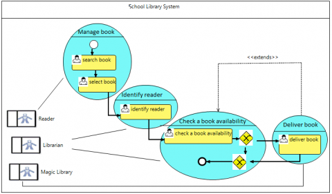
Figure 3. Exemple of BPSUC
Figure 3 represents an example of a BPSUC model. This diagram contains an OUPackage named “School Library System” that combines the roles of both a UML Package and a BPMN lane elements. The OUPackage has four UCFragments namely “Manage book”, “Identify reader”, “Check a book availability”, and “Deliver book”. Each UCFragment represents both a UML Use Case and a sequence of BPMN elements as well as trace relationships between them. For example, the UCFragment “Manage book” is a representation of a UML Use Case element named “Manage book”. In addition, it contains three OUActors namely “Reader”, “Librarian” and “Magic Library”. Those OUActors are used to represent both a BPMN lane as well as an UML Actor roles together. Note the “Extends” relationship from “Deliver book” to “Check a book availability”.
4.3 Transformation models
Transformation models provide the ground to define and apply automatic transformation rules to produce source models from other ones even though they belong to different abstraction levels. Each transformation model (TransM) consists of sets of transformation rules (STRs), which aim to generate target models (TM) from source models (SM). Formally, the relationship between TransM, STR, TM and SM is written as follows:
$\operatorname{Tr} a n s M_{S T R}=S^{M} \stackrel{S T R}{\longrightarrow} T^{M}$ (1)
In our approach, we base on the mapping between BPMN, BPSUC and UML use case models presented in Table 2 to propose two sets of forward and backward transformation rules. These rules are depicted in Table 3 and are expressed in natural language.
Table 3. Forward and backward transformation rules
|
from BPSUC into BPMN and UML use case |
From BPMN and UML use case model into BPSUC |
|
R1: Transform each OUPackage into a BPMN Lane that incorporates lane sets and into a UML Package |
R1’: Transform each lane that incorporates lane sets and the corresponding UML package into an OUPackage |
|
R2: Transform each OUActor into a BPMN lane which does not incorporate lane sets and into a UML Actor |
R2’: Transform each lane that does not incorporate lane sets and the corresponding UML actor into an OUActor |
|
R3: Transform each UCFragment into a UML use case and into a fragment |
R3’: Transform each fragment and its corresponding UML use case into a UCFragment |
|
R4: Transform each association into a BPMN Fragment within the lowest nesting level of lanes and a UML association |
R4’: Transform each Fragment within the lowest nesting level of lanes and the corresponding UML association into an association |
|
R5: Transform each “include” relationship into a UML” include” relationship |
R5’: Transform each Fragment that appears multiple Times and the corresponding UML Includes relationships into an includes relationship |
|
R6: Transform each “extend” relationship into a UML “extend” relationship and a BPMN inclusive Gateway |
R6’: Transform each inclusive gateway between two fragments into an “extends” relationship and an inclusive gateway |
|
R7: Transform each “extend” relationship into a UML “extend” relationship and a BPMN exclusive gateway |
R7’: Transform each exclusive gateway between two fragments into an extends relationship and an exclusive Gateway |
|
R8: Transform each extension point into a UML extension point |
R8’: Transform each condition of a sequence flow with the fragment label that corresponds to the extending UC and an UML extension point into an extension point |
The first column of Table 3 presents the proposed forward set of transformation rules. This set of rules allows generating automatically a BPSUC diagram from a BPMN and a UML use case models. Therefore, SM, TM, and STRs will take the following values:
Formally, the relationship between TransM, SBPMN, SUMLUC and TBPSUC may be expressed as follows:
$TransM_{Forward} =S^{B P M N}+S^{U M L U C} \stackrel{R 1 \ldots R 8}{\longrightarrow} T^{B P S U C}$ (2)
Two cases are possible to generate BPSUC elements:
(1) The first case consists of transforming BPMN elements (BPMN!Elements) and UML use case elements (UMLUC!Elements) into their trace and synchronization elements (tr&synE) (new modeling elements) of BPSUC.
More precisely, the new modeling elements, notably OUActor, OUPackage and UCFragment, are derived from the elements they trace. The definition of their transformation rules should be established according to the following procedure:
TransM $_{\text {Tr} \& S y n E}=S^{B P M N ! E l e m e n t}+S^{U M L U C ! E l e m e n t}\stackrel{R X}{\rightarrow} T ^{B P S U C ! t r \& s y n E}$ (3)
For example, the transformation rule R1 allows generating the OUPackage that is a trace and synchronization element of the BPMN lane and UML use case package elements. Therefore, R1 is defined as follows:
$\operatorname{Trans} M_{T r \& S y n E}=S^{B P M N ! L a n e}+S^{U M L U C ! P a c k a g e}\stackrel{R 1}{\rightarrow} T^{B P S U C ! O U P a c k a g e}$ (4)
(2)The second case is to derive the nonrelated elements (NRE) from either, the use case model or BPMN model. In fact, in a BPSUC, each element that represents a nonrelated element requires only the model where this nonrelated element belongs to initially. In this manner, the input of these rules is the BPMN model if the element belongs to BPMN, or the UML model UML use case will be taken as the input of this transformation rule. An example of this case is the generation of a UserTask element, which requires only the BPMN model as an input of the transformation rule:
$Trans{{M}_{NRE}}={{S}^{BPMN!UserTask}}\underrightarrow{R(UserTask)}{{T}^{BPSUC!UserTask}}$ (5)
The second column of Table 3 represents the backward set of transformation rules that fulfills the reverse direction of the forward set of transformation rules. The values of SM, TM, and STRs are changed as follows:
We follow the same transformation logic applied on the forward set of transformation rules to define the backward set of transformation rules. Hence, the transformation rules of related elements are defined according to the following procedure:
$Trans{{M}_{Backward}}={{S}^{BPSUC!Element}}\underrightarrow{R1'...R8'}{{T}^{BPMN!Element}}+{{T}^{UMLUC!Element}}$ (6)
The transformation rules of nonrelated elements are defined according to the following procedure:
$Trans{{M}_{Backward}}={{S}^{BPSUC!Element}}\underrightarrow{R1'...R8'}{{T}^{BPMN!Element}}/{{T}^{UMLUC!Element}}$ (7)
The proposed forward and backward transformation models enable to ensure a bidirectional transformation between BPMN and UML use case models and BPSUC diagram, which in turn ensures the synchronization between them:
$Trans{{M}_{Backward}}={{S}^{BPSUC!Element}}\underrightarrow{R1...R8+R1'...R8'}{{T}^{BPMN!Element}}/{{T}^{UMLUC!Element}}$ (8)
4.4 Traceability of the BPMN and UML use case models
Because Traceability between BPMN and UML use case models is carried out basing on both the integrated (meta) model and the set of forward transformation rules (from BPMN & UML use case into a BPSUC model). As we aforementioned in subsections 4.1 and 4.2, both the proposed integrated trace&synch metamodel and its instantiation (BPSUC model) incorporate all BPMN and UML use case as well as new modeling elements in a unified form. Traceability links are well established in the integrated trace&synch metamodel by the new modeling elements namely OUPackage, OUActor, Fragment, and UCFragment as well as the proposed new associations between BPMN and UML use case model elements. Each new metaclass in the integrated trace&synch metamodel is a representation of traceability links and a connection of a specific related element couple. An instance of that is, for example, the OUActor, which represents a traceability link between a BPMN lane and a UML actor. Unlike transformation rules that define only bijective and unidirectional relationships between related elements, the integrated metamodel enables to deal with all relationships and relationship types. In addition, the BPSUC model allows not only to visualize the trace links graphically but also to represent the nonrelated BPMN and UML use case model elements. Therefore, nonrelated elements are also traced within BPSUC by identical elements. Further, our approach makes it possible to derive automatically the traceability between BPMN and UML use case models through the set of forward transformation rules (cf the second column of Table 3). The execution of these rules automatically derives a complete BPSUC model from BPMN and UML use case models.
4.5 Synchronization of the BPMN and UML use case models
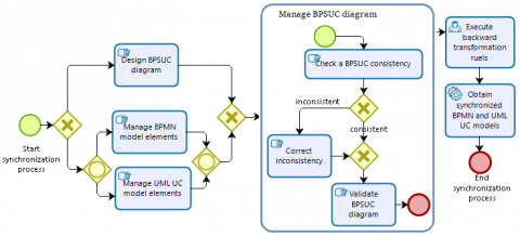
Synchronization between BPMN and UML use case models is carried out semi-automated basing on both the integrated trace&synch (meta) model and the sets of transformation rules between BPMN and UML Use Case models on the one hand, and a BPSUC model on the other hand. We present the process of synchronization between BPMN and UML Use Case models by a BPMN diagram as it is depicted in Figure 4. Our synchronization approach is flexible to support the two ways to synchronize BPMN and UML use case models; either by modifying the initials models or directly use of the BPSUC model.
Figure 4. Process of synchronization between BPMN and UML Use Case models
(1) In the first case, the requirement designers may want to add a new UML use case while at the same time the business designers may change the name of a lane. A direct generation of a UML use case model from the BMPN model (or the inverse direction) is not sufficient to consider changes on both initial models because it leads to the loss of modifications occurred on the target model. Additionally, the effects of such changes need to be observed before propagating them in other models to avoid unintentional changes and to prevent from the violation of structural well formedness constraints. To tackle this problem, we propose in the first step to execute the proposed forward transformation rules that generate the BPSUC from BPMN and the UML use case models (Execute forward transformation rules).
In this way, all modifications which arise in the BPMN or/and the UML use case model are taken into consideration by the BPSUC model.
(2) In the second case, we focus on the investigation of the BPSUC model to be a means for business and requirement designers to modify BPMN and UML use case model elements directly. Hence, as it incorporates all BPMN and UML use case model elements and the trace links between them, BPSUC allow the business and the requirement designers to use it together. Now, BPSUC exhibits as an intermediate model for the business and requirement designers to intervene together to check, correct and validate inconsistencies before propagating the modifications to their initial models (BPMN and UML use case models) (Manage a BPSUC diagram). BPSUC helps then business and requirement designers to estimate the impacts of updating, adding or removing some of business or system functionalities.
Any occurred modification, namely insertion, deletion or alteration on a BPSUC element means the change of corresponding BPMN and UML use case model elements. For instance, within BPSUC model an OUActor represents a combined use of both the BPMN lane and the UML actor elements. Therefore, adding a new OUActor is enough to establish synchronization between a BPMN lane and a UML actor because OUActor is a representation of both, the lane and the actor elements. Consequently, a BPSUC model gives the opportunity to obtain a BPMN model synchronized with the UML Use Case model. While the BPSUC is well synchronized with the modifications made on the initial models until this step, these models are not yet synchronized with each other. Therefore, the execution of the set of backward transformation rules is required to generate automatically new versions of BPMN and UML use case models from BPSUC model (Execute backward transformation rules). Now, the generated models are being synchronized with the BPSUC model as well as with each other (Obtain synchronized BPMN and UML Use Case models.
The implementation process of our approach consists of developing an editor by using the Graphical Modeling Framework (GMF) plugin within the Eclipse environment (see Figure. 10 in appendix B). This editor allows designing BPSUC models according to the integrated trace&synch metamodel. On the other hand, we develop two tools to implement the sets of forward and backward of transformation rules:
Figure 5 depicts an overview of the implementation process of our trace Model.
Figure 5. Overview of the implementation process of our trace approach
5.1 Implementation of the BPMN supporting use case model
Within the Graphical Modeling Framework (GMF), we develop a fully functional graphical editor that implements the proposed integrated metamodel and allows designing its instantiation. Hence, we choose ECore as the language that describes our integrated trace&synch metamodel. Then, we develop a toolbox to design an integrated trace&synch model according to our integrated metamodel. Business and requirement designers may use our editor to deal with synchronization and traceability between BPMN and UML use case models by modeling and managing together the existing BPMN and the UML use case model elements within a single model (cf. Figure 6). Furthermore, it combines the use of related concepts through the UCFragment, OUActor and OUPackage elements. To model the elements of BPSUC within our editor, we do not introduce new syntax and notations, but rather we use the original syntax of the existing BPMN and use case model elements. To avoid introducing new graphical notations for new modeling elements, we extend some existing BPMN and UML notations to ensure a user-friendly representation, which facilitates the understanding of BPMNSC model. Then, we develop our editor as an internal plugin that can be installed and used within the eclipse-modeling framework as an eclipse project.
5.2 Tools for Traceability and Synchronization between BPMN, UML use case and BPMN-Supporting Use Case models
We develop two tools called BPMN&UC2BPSUC and BPSUC2BPMN&UC using the Eclipse Modeling Framework (EMF). Since BPMN and UML are common standard modeling notations, which are widely experimented, many standard plugins and tools are developed and validated to support them. Among the existing plugins, we choose to use conFigure.d plugins within EMF; we use Eclipse BPMN2 modeler plugin to design BPMN models, and the UML designer plugin to design UML use case models. These plugins have internal metamodels that strictly correspond to the OMG specifications. Thus, we integrate their metamodels in the EMF environment to use them during the execution of our tools. We also integrategate our trace&synch metamodel into the editor to display design BPSUCs models. The prosed sets of transformation rules are implemented by using the Atlas Transformation Language (ATL), which is available as a plugin in EMF 12].
In the BPMN&UC2BPSUC tool, which automate the transformation from a BPMN and a UML use case models into a BPSUC model, the execution of the transformation rules takes as input two files: (1) A file with “.bpmn” as extension. This file must comply with the BPMN2.0 metamodel. (2) a file with “.uml” extension that complies with the UML metamodel. It generates as output a BPSUC model with “.BPSUC” extension (cf. Figure 6).
Figure 6. BPSUC notation and the editor environment caption
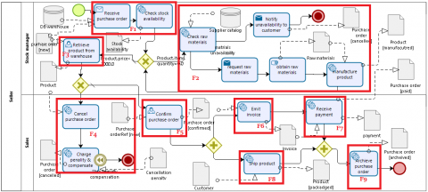
Our illustrative case study (cf. Figure 7) describes a typical business process for online purchasing and selling. The process starts when a customer selects the purchasing product and adds it to the cart in order to specify an online purchase order and send it to the seller. Before filling his personal information, the customer may cancel preparing the purchase order. Otherwise, he should fill his personal information and send the online purchase order to the stock manager. Once the online purchase order is received, the stock manager checks the availability of the ordered items in the warehouse to see if there are enough products to fulfill the purchase order. If not, the restock process is performed to reorder raw materials basing on the suppliers catalog and manufacture the ordered products. This activity may be repeated multiples times in the same business process instance. An exceptional case occurs when raw materials are unavailable. If not, the sales confirm the purchase order, creates an invoice and starts collecting and packaging items for shipment.
The process finishes when the sales receives the payment. and archives the delivered order. On the other hand, purchase order cancellation requests may occur before the purchase order is confirmed. Thus, the sales proceeds to a purchase order cancellation and charges a penalty to the customer.
We decompose the online purchasing and selling BPMN model into fragments according to our fragment definition (c.f Figure 7). For example, the fragment F1 is limited by the data objects “Cart” and “Product” which represent the input business objects, and the data object “Purchase order” that represents the output business object. As the fragments F3, F5-F9 are composed of one task, the name of each one of them is the name of the task it contains. For example, F2 is called “Retreive product from warehouse”, whereas F1, F4, and F5 contain many tasks. Therefore, we manually name them as follows;
By applying the transformation rules of Bouzidi et al. [9], we obtain the use case diagram presented in Figure 8 (you can consult to show the transformation rules details).
Figure 7. An online purchasing and selling process
Figure 8. The generated use case diagram for the online purchasing and selling business process model
Both the BPMN model presented in Figure 7 and the use case diagram presented in Figure 8 may be designed together by using our new diagram and basing on the mapping between the BPSUC, BPMN and the use case elements. Figure 9 presents the designed BPSUC diagram. It is noted that this diagram may be manually designed by designers as well as automatically generated by executing the tool “BPMN&UC2BPSUC”.
In Figure 9, we show that each fragment and the corresponding use case, these elements are combined and represented together through the UCFragment. For example, we combine the Fragment F1 with the use case “Manage preparing purchase order” to be represented together by the UCFragment “Manage preparing purchase order”. This UCFrament is able to represent explicitly the F1 elements (“receive purchase order, “check stock availability”). Similarly, we present each actor and the corresponding empty lane by an OUActor, and the package “Seller” with the lane “Seller” by the OUPackage “Seller”. For example, the actor “Stock manager” and the empty lane “stock manager” by the OUActor “stock manager”.
Now, suppose that the business and systems designers are working together on the BPSUC model, and they have agreed to evolve their business and system functionalities to manage the online purchasing and selling. Consequently, they add a new UCFragment named "Prepare purchase order" and a new OUActor named “Customer” to handle the purchase preparing by the Customer. As the UCFragment is a trace link between a sequence of BPMN elements and a UML use case element, it represents simultaneously UML use case named “Prepare purchase order” and a fragment that incorporates two tasks named "Check product items" and "Fill cart". However, the initial models (BPMN and UML use case models) are not synchronized with BPSUC model after the changes. To synchronize them, we should execute BPSUC2BPMN&UC tool that generates” from the BPSUC model of “Online purchasing and selling” new versions of the BPMN and the UML use case models. Hence, the execution result of this tool is a BPMN model that incorporates two tasks named items" and "Fill cart", which belong to a new pool named “Customer”, and a UML use case model augmented by a new use case named “Prepare purchase order” and a new Actor named “Customer”.
Figure 9. Traceability between BPMN, UML use case and BPSUC models
7.1 Comparison of our approach and existing approaches
The current approach explores model transformations and integration techniques to bridge the gap between the BPMN model and the UML use case diagram. Thereby, defining a trace&synch metamodel and a new diagram as well as a chain of transformation rules, which ensure backward and forward transformations between BPSUC, BPMN and the use case diagrams. To evaluate the trace&synch metamodel and BPSUC, we compare them to the related works, which introduce a traceability and/or a synchronization (meta)model according to the following criteria:
Table 4 presents the results of the comparison. The columns correspond to the proposed approaches and each row in the table represents a comparison criterion.
Table 4. Comparison of the existing works and our approach
|
|
Drivalos et al. [17] |
Haidrar et al. [25] |
Laghouaouta et al. [22] |
Meier and Winter [18] |
Haidrar et al. [24] |
Poggio and Suzana [23] |
Wautelet and Poelmans [26] |
Our approach |
|
C1 |
New modeling language |
SYSML model |
Generic approach |
Requirements, class diagrams, and source code. |
BPMN models |
computational models of EA |
RUP/UML BUC Model and the BPMN |
BPMN and Use Case models |
|
C2 |
P |
Y |
N |
P |
Y |
P |
N |
Y |
|
C3 |
N |
N |
N |
Y |
Y |
N |
P |
Y |
|
C4 |
N |
N |
N |
Y |
N |
N |
Y |
Y |
|
C5 |
CSs |
CS+T |
CS+T |
CS+T |
N |
N |
CS+T |
CS+T |
Legend: Y= Yes, N= No, P= partially provided, CS= case study, T= Tool
According to the comparison results, our approach satisfies all the evaluation criteria. Although, the approaches proposed by Meier and Winter, Laghouaouta et al., and Poggio and Suzana [18, 22, 23] may support BPMN and UML use cases, the proposed metamodel concepts are specified by black box meta-classes, which cannot be precise enough. In addition, due to their generic nature, the proposed traceability metamodel cannot express case specific structural constraints, such as the number or types of elements that can be linked in a traceability link and therefore a constraint language is needed to specify these structural constraints. Therefore, considerable efforts are required to refine them. Moreover, the approach in [Towards Traceability Metamodel for Business Process Modeling Notation] represents explicitly relationships between BPMN model elements through the extension of properties of its elements. Similarly, the approach proposed by Wautelet and Poelmans [26] provides a framework that allows modeling both the strategic, tactical and operational layers of a business model in the form of an integrated model. However, the authors Pavalkis et al., and Wautelet and Poelmans [24, 26] focus only on the traceability business modeling problem, while the integration of the information system models with the business model is out of their scope. Hence, no approach explicitly defines the traceability between the UML use case and the BPMN models. On the other hand, the established relationships between the model elements are specified only at the metamodel level, while at the model level, they are represented separately. In this case, users cannot explicitly visualize the combined use of elements of these heterogeneous models and traceability links between the source models may be lost at this level.
7.2 Limits of our approach
One of the main downsides of the proposed approach is that we evaluated and refined the syntax and semantics of BPSUC only through two illustrative examples, which are not sufficient to validate BPSUC expressiveness. Hence, the BPMN model presented in Figure.7 does not incorporate all BPMN elements. Similarly, the use case diagram is simple to validate the accuracy of the diagram BPSUC. Therefore, we are working on testing BPSUC through more complex case studies to estimate its accuracy and correctness. Moreover, synchronization is performed only by applying the forward or the backward transformation rules, which must regenerate all elements even if they are not affected by the changes made. We are working to enhance our transformation to ensure incremental transformation rules that should regenerate only the elements impacted by the changes. In addition, our intermediate diagram does not allow detecting automatically changes made on the source models (for example BPMN) only if we re-execute the transformation from the source model into BPSUC. We aim to enhance BPSUC tool to be able to detect the changes made on the source models automatically and to indicate the elements that will be affected by the changes.
In this paper, we addressed the traceability and synchronization challenges between business process and requirement models. To do this, we based on both the integration technique and the model transformation to propose a traceability approach for the BPMN and the UML use case models. In the first step, we defined an integrated metamodel that incorporates all BPMN and use case model elements. Next, we defined a BPSUC model as an instantiation of the proposed integrated trace&synch metamodel. Using this model to design together BPMN and UML use case models ensures maintaining the BPMN and the use case models always synchronized and coherent.
Moreover, we proposed two sets of forward and backward model transformation chains between BPMN and UML. To prove the feasibility of our approach, we developed a proof of concept prototype in the form of an editor that supports our integrated trace&synch metamodel and allows visualizing, designing and modifying BPSUCs with respect to the proposed integrated trace&synch metamodel. Besides, we implemented two tools, which computerize the proposed sets of transformation rules. On the other hand, we applied our approach to an illustrative example.
In future research, we are looking forward to establish and maintain traceability and synchronization between UML use cases and sequence diagrams.
|
SM |
Source Model |
|
TM |
Target Model |
|
TransM |
Transformation model |
|
STRs |
transformation rules |
|
R(x) |
Transformation rule of the element x |
|
NRE |
non-related elements |
|
RE |
related elements |
|
Sm!e |
The element e of the source model m |
|
Sm!e |
The element e of the target model m |
Appendices
Appendix A
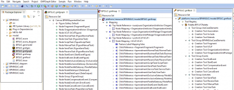
This appendix presents an extract of the different part for implementing the editor that allows of our new diagram BPSUC.
Figure 10. Extract of the editor for developing the new diagram BPSUC
Appendix B
This appendix represents how we use the BPSUC as an internal plugin within the eclipse-modelling framework.
Figure 11. Using the BPSUC as an internal plugin within the eclipse modelling framework
[1] OMG-MDA. (2015). MDA Guide revision 2.0.
[2] Object Management Group. (2012). Unified Modeling Language: Superstructure, formal.2012-05-07. ISO as the 2012 edition standard: ISO/IEC 19505-2: 2 0 1 2 ( E.
[3] Object Management Group. (2013). Business Process Model and Notation (BPMN)-Version 2.0.2. OMG.
[4] Drivalos, N., Paige, R., Fernandes, K.J., Kolovos, D. S. (2008). Towards rigorously defined model-to-model traceability. ECMDA, Berlin, Germany, 17–26.
[5] IEEE Standards Board. (1990). IEEE Standard Glossary of Software Engineering Terminology. IEEE Std 610.12-1990. IEEE Press, Piscataway.
[6] Winkler, S., Pilgrim, J. (2010). A survey of traceability in requirements engineering and model-driven-development. Journal of Software and Systems Modeling, 9(4): 529-565. https://doi.org/10.1007/s10270-009-0145-0
[7] Ramesh, B., Edwards, M. (1993). Issues in the development of a requirements traceability model. Proceedings of the IEEE International Symposium on Requirements Engineering, IEEE Computer Society, New York, pp. 256-259. https://doi.org/10.1109/ISRE.1993.324849
[8] Aizenbud-Reshef, N., Nolan, B.T., Rubin, J., Shaham-Gafni, Y. (2006). Model traceability. IBM Systems Journal, 45(3): 515-526.
[9] Bouzidi, A., Haddar, N., Ben Abdallah, M., Haddar, K. (2017). Deriving use case models from BPMN models. Proceedings of the 14th International Conference on Computer Systems and Applications (AICCSA), Hammamet, Tunisia, pp. 238-243. https://doi.org/10.1109/AICCSA.2017.49
[10] Cruz, E.F., Machado, R.J., Santos, M.Y. (2015). Bridging the gap between a set of interrelated business process models and software models. Proceedings of the International Conference on Enterprise Information Systems, 2: 338-345.
[11] Park, G., Fellir, F., Hong, J.E., Garrido, I.L., Noguera, M., Chung, L. (2017). Deriving use cases from business processes: A goal-oriented transformational approach. Proceedings of Symposium on Applied Computing (SAC) ACM, pp. 1288-1295. https://doi.org/10.1145/3019612.3019789
[12] Przybylek, A. (2014). A business-oriented approach to requirements elicitation. Proceedings of the 9th International Conference on Evaluation of Novel Approaches to Software Engineering (ENASE’14), Lisbon, pp. 152-163. https://doi.org/10.5220/0004887701520163
[13] Bulbun, G.U.D., Shahzada, H.M.A. (2016). BPMN process model checking using traceability. Proceedings of the 6th Conference of Innovation of Computer Technology (INTECH), pp. 694-699. https://doi.org/10.1109/INTECH.2016.7845098
[14] Jouault, F., Allilaire, F., Bézivin, J., Kurtev, I., Valduriez, P. (2006). ATL: A QVT-like transformation language. 21st ACM SIGPLAN Symposium on Object-oriented Programming Systems, Languages, and Applications, pp. 719. https://doi.org/10.1145/1176617.1176691
[15] Silingas, D., Butleris, R. (2008). UML-intensive framework for modeling software requirements. Proceedings of the 14th International Conference on Information and Software Technologies, pp. 334-342.
[16] Haidrar, S., Bencharqui, H., Anwar, A.J., Ruel, MB., Roudiès, O. (2017). On the use of model transformation for requirements trace models generation. Proceedings of the RE Workshops, pp. 26-35.
[17] Drivalos, N., Kolovos, D.S., Paige, R.F., Fernandes, K.J. (2009). Engineering a DSL for software traceability. Edited Software Language Engineering, Springer, Berlin, Heidelberg, pp. 151-167. https://doi.org/10.1007/978-3-642-00434-6_10
[18] Meier, J., Winter, A. (2018). Traceability enabled by metamodel integration. Software Technik-Trends, 38( 2).
[19] Bouzidi, A., Haddar, N., Ben Abdallah, M., Haddar, K. (2018). Alignment of business processes and requirements through model integration. Proceedings of the 15th International Conference on Computer Systems and Applications (AICCSA)., Aqaba, Jordan, pp, 1-8.
[20] Khelladi, D.E., Kretschmer, R., Egyed, A. (2018). Change propagation-based and composition-based co-evolution of transformations with evolving metamodels. MoDELS, 404-414. https://doi.org/10.1145/3239372.3239380
[21] Cleland-Huang, J., Hayes, J., Domel, J.M. (2009). Model-Based Traceability. TEFSE (2009), 6-10.
[22] Laghouaouta, Y., Anwar, A., Nassar, M., Coulette, B. (2017). A dedicated approach for model composition traceability. Journal of the Information and Software Technology, 91: 142-159. https://doi.org/10.1016/j.infsof.2017.07.002
[23] Poggio, J.R, Suzana, R. (2017). Towards a models traceability and synchronization approach of an enterprise architecture. Proceedings of the 29th International Conference on Software Engineering and Knowledge Engineering, pp. 24-29.
[24] Pavalkis, S., Nemuraite, L., Milevičienė, E. (2011). Towards traceability metamodel for business process modeling notation. Skersys, T., Butleris, R., Nemuraite, L., Suomi, R. (eds) Building the e-World Ecosystem. I3E 2011. IFIP Advances in Information and Communication Technology, vol 353. Springer, Berlin, Heidelberg, 2011.
[25] Haidrar, S., Anwar, A., Roudies, O. (2017). A SYSML-based Approach to manage stakeholder requirements traceability. Proceedings of the 14th International Conference on Computer Systems and Applications (AICCSA), Hammamet, Tunisia, pp. 202-207. https://doi.org/10.1109/AICCSA.2017.183
[26] Wautelet, Y., Poelmans, S. (2017). An integrated enterprise modeling framework using the RUP/UML business use-case model and BPMN. Poels, G., Gailly, F., Serral Asensio, E., Snoeck, M. (eds). The Practice of Enterprise Modeling. PoEM 2017. Lecture Notes in Business Information Processing, Springer, Cham, p. 305. https://doi.org/10.1007/978-3-319-70241-4_20