Nabil Boudjoghra* | Fares Innal
© 2023 IIETA. This article is published by IIETA and is licensed under the CC BY 4.0 license (http://creativecommons.org/licenses/by/4.0/).
OPEN ACCESS
The work presented was aimed primarily at contributing to the control of risks relating to an industrial installation by means of a safety instrumented system (SIS), through a global approach defined by the IEC 61508 standard which goes from risk analysis to the evaluation of SIS. The IEC 61508 approach consists of industrial risk analysis which is a process used to identify the risks inherent in an industrial system and estimate the levels of these risks using several methods, tools and software. Then, the reduction of risks deemed unacceptable in the risk analysis phase to an acceptable level using SIS. The extent of the reduction to be achieved determines the level of performance that the SIS must have to achieve this reduction assigned to it (required SIL). The real performance of SIS (real SIL) must meet the corresponding requirements. Otherwise, technical modifications must be made to the SIS. The application of the IEC 61508 approach addresses the risk analysis of butane product overflow stored in a tank and the verification of the ability of an SIS installed at this tank to control this risk. And if necessary, propose technical modifications to optimize the performance of the SIS. Risk analysis conducted using the HAZOP (HAZard and OPerability) method to identify critical accident scenarios, PHAST (Process Hazard Analysis Software Tool) software and risk matrix to estimate risk level of a given accident. Verification of the ability of an SIS installed at the tank to control the risk deemed unacceptable in the risk analysis phase is carried out by The LOPA (Layer Of Protection Analysis) method for the allocation of the required SIL for the SIS and SIL module of the GRIF (GRaphical Interface for reliability Forecasting) software to calculated real SIL of SIS. Depending on the results obtained (required SIL > real SIL), recommendations likely to strengthen the reliability of SIS are proposed (modification of the test policy and the architecture of the constituent elements of the SIS) in order to achieve the required SIL. And thus secure our system.
IEC 61508, safety instrumented system (SIS), Safety Integrity Level (SIL), HAZard and OPerability (HAZOP) method, Layer Of Protection Analysis (LOPA) method, Process Hazard Analysis Software Tool (PHAST) software, GRaphical Interface for Reliability Forecasting (GRIF) software
Safety functions play a key role in preventing accidents that may occur in industrial installations. They come into action when the industrial process is in abnormal conditions and a dangerous situation is likely to develop, the systems performing these functions are the safety barriers, and a particular type of barrier includes the safety instrumented systems (SIS). SIS and the safety integrity of the safety functions they perform are the main topic of this article.
In view of the critical roles of SIS for controlling technological risks as security barriers, their capacities to perform as intended security functions must be studied. And for this, international standards known as "functional safety" have been developed, in particular the main European reference which is IEC 61508 [1] on the functional safety of systems (Electrical/Electronic/Electronic Programmable) relating to safety. This standard adopts a risk-based approach to propose a general method for specifying security requirements and covers the entire security lifecycle of systems and software. In addition, this generic standard serves as the basis for the development of product and industry application standards.
The main objective of the work presented is to verify, through an evaluation by probabilistic approaches based on the international standard for functional safety IEC 61508, whether a safety instrumented function set up at the level of the TK-411 butane storage tank makes it possible to achieve the necessary safety target with regard to the critical risk "Excess level of butane in the tank". Depending on the results obtained, recommendations likely to strengthen the reliability of SIS are proposed in order to achieve the required level of safety integrity.
TK-411 is a tank with a capacity of 20,000 tons of butane which is a flammable and explosive product under certain conditions. This tank is controlled by a control and monitoring system that appears weak; this weakness is confirmed by the company's feedback recording accidents at the tank due in particular to product overflow. This is why this reservoir constitutes an important subject for us to study.
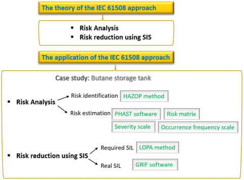
The proposed methodology is performed to achieve the objective of study as follow (Figure 1).
Figure 1. Methodology steps
The methodology revolves around two axes which are the presentation of the theory of the IEC 61508 approach and the application of the latter. This approach aims to analyze industrial risks and especially control them using SIS.
The IEC 61508 approach consists of industrial risk analysis which is a process used to identify the risks inherent in an industrial system and estimate the levels of these risks using several methods, tools and software. Then, the reduction of risks deemed unacceptable in the risk analysis phase to an acceptable level using the SIS.
The extent of the reduction to be achieved so that the risk becomes at an acceptable level determines the level of performance that the SIS must have to achieve this reduction assigned to it (required SIL). Once the required SIL is assigned, the real performance of SIS (real SIL) must meet the corresponding requirements. It consists in the quantification of the PFDavg of SIS (reliability of SIS). The obtained value must not exceed the target measure (required SIL) specified during the SIL allocation stage. Otherwise, technical modifications must be made to the SIS.
The application of the IEC 61508 approach addresses the risk analysis of butane product overflow stored in a tank and the verification of the ability of an SIS sut up at this tank to control this risk. And if necessary, propose technical modifications to optimize the performance of this SIS.
The case study concerns a butane storage tank "TK411" belongs to an LNG complex (GL1K) located in Skikda-Algeria.
Risk analysis consist to identify different accident scenarios that may occur in TK411 and estimation of these accidents.
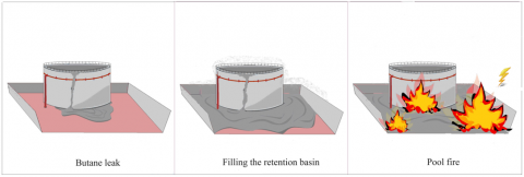
HAZOP analysis method leads to identify different accident scenarios resulting from parameters deviations. We limit ourselves to study one accident scenario: “Butane level increase in TK411 tank leads to a leak, causing the Pool fire phenomenon”.
To estimating risk, it should firstly know de definition of risk which is the combination of the occurrence frequency of an accident and the severity of its consequences. So. First, we will determine the severity of the consequences using the PHAST software, by modeling the thermal effects of the accident and relying on an evaluation scale specific to the company defining categories of severity in relation to the presence people in areas affected by thermal effects. Then, we will determine the tolerable level of risk by the company's risk matrix and thus we will extract the minimum tolerable frequency based on the company's occurrence frequency scale.
To reduce a risk, you must reduce at least one of its parameters (its occurrence frequency (and/or) its severity). According to IEC 61508, the SIS is the safety barrier which must put the risk in its tolerable frequency and therefore the risk in a tolerable level.
The requirements required at the SIS to carry out this mission determines the level of performance that the SIS must have (required SIL). It will be calculated using the LOPA method.
The ability of the SIS to carry out this mission concers the real performance of SIS (real SIL). It consists in the quantification of the PFDavg of SIS (reliability of SIS). which will be calculated by GRIF software.
If (real SIL≥required SIL) the SIS is capable of controlling the risk, if (real SIL<required SIL) the SIS is not capable of controlling the risk, hence the need for technical modifications to optimize the performance of SIS.
IEC 61508 is the only multisectoral standard that addresses the whole issue of Electrical, Electronic and Electronic Programmable (E/E/EP) systems; it addresses both hardware and software security. It is also the only highly technical standard that provides keys, which you just need to comply with to achieve a goal.
This international standard sets out a generic approach for all safety lifecycle activities for systems comprised of (E/E/PE) elements that are used to perform safety functions. This unified approach has been adopted in order that a rational and consistent technical policy be developed for all electrically-based safety-related systems. A major objective is to facilitate the development of product and application sector international standards based on the IEC 61508 series.
IEC 61508 is based on two concepts that are fundamental to its application: the safety life cycle and safety integrity levels.
This standard is performance-oriented, leaving it up to the user to carry out his risk analysis and it offers him the means to reduce this risk.
It describes the principles, techniques and measures for achieving functional safety of E/E/EP safety related systems. A special type of these systems is the safety instrumented systems (SIS) [1].
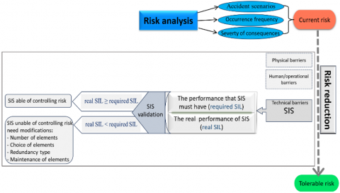
IEC 61508 is a standard that provides a structured approach relying on risk analysis in order to establish the safety requirements for SIS to control this risk. It aims at designing and operating the SIS within reliability confidence that meets these requirements [1, 2]. IEC 61508 approach diagram is shown in Figure 2.
4.1 Risk analysis
Risk is the combination of the occurrence frequency of an accident and the severity of its consequences [3].
Risk analysis is a process used to identify the risks inherent in an industrial system and estimate the levels of these risks using several methods, tools and software [4, 5].
Risk identification is used to comprehend the nature of risk and to determine the accident scenarios can occur in system.
Risk estimation is used to estimate the frequency of accident occurrence and its consequences.
Risk analysis can be carried out, depending on the quality of the information and data collected on the system by several ways, risk analysis methods such as HAZOP, FMECA (Failure Modes, Effects and Criticality Analysis), PHA (Preliminary Hazard Analysis), FTA (Fault tree analysis). Modeling and calculation software such as PHAST, ALOHA (Areal Locations of Hazardous Atmospheres).
4.2 Risk reduction
Risk reduction concerns risks deemed unacceptable in the risk analysis phase.
To reduce a risk, you must reduce at least one of its parameters (its occurrence frequency (and/or) its severity).
For this, technical, physical and human/operational security barriers are used [6].
According to IEC 61508, the SIS is the safety technical barrier which must put the risk in its tolerable frequency and therefore the risk in a tolerable level.
4.2.1 Safety instrumented system (SIS)
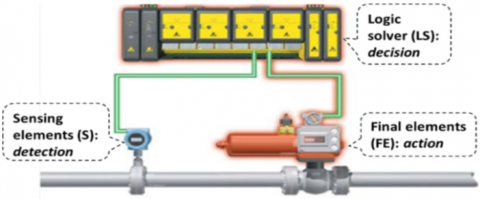
Safety instrumented system is a safety technical barrier whose objective is to achieve or maintain a safe state of the process when a dangerous event occurs. SIS includes sensors, transmitters, logic solver and final control elements [7]. A typical composition of a SIS is represented in Figure 3.
- input elements (sensors, detectors, etc.) which monitor the evolution of the parameters representative of the installation (temperature, pressure, flow, level, etc.).
- logical units (PLC, API, DCS) programmabl controller which collect information from the input element subsystem and carry out the decision-making process.
- terminal elements (emergency stop valves, pumps, alarms, etc.) which act, under the order of the logic units subsystem, on the installation to neutralize its drift by putting it in a safe state.
4.2.2 Safety Integrity Level (SIL)
The performance of an SIS is determined in terms of safety integrity level (SIL).
To specify SIL, IEC 61508 specifies two reliability metrics, depending on how often the SIS is requested to respond to hazardous events: The average probability of dangerous failure on demand (PFDavg) and the probability of dangerous failure per hour (PFH). The first measure is appropriate for SIS called upon at a low frequency (less or equal to once per year), whereas the second one is relevant when such frequency is high (more than once per year) or continuous [8]. The accordance between SIL levels and the above indicators is presented in Table 1.
Table 1. SIL according to PFDavg and PFH [1]
|
SIL |
PFDavg |
PFH(h)-1 |
|
4 |
≥10–5 to < 0–4 |
≥10–9 to <10–8 |
|
3 |
≥10–4 to <10–3 |
≥10–8 to <10–7 |
|
2 |
≥10–3 to <10–2 |
≥10–7 to <10–6 |
|
1 |
≥10–2 to <10–1 |
≥10–6 to <10–5 |
4.2.3 Required safety integrity level to the SIS (required SIL)
Required SIL is the performance level that the SIS must have to achieve the reduction assigned to it so that the risk becomes at an acceptable level.
It consists in the quantification of the PFDavg or PFH (reliability required of the SIS).
The IEC 61508 standard describes several methods of allocating required SIL [7-11]. Some are of qualitative types (the risk graph [8], the criticality grid [9], etc.) and others are quantitative (LOPA: Layer Of Protection Analysis [12, 13]).
4.2.4 Real safety integrity level of the SIS (real SIL)
Once the required SIL is assigned, the real performance of SIS must meet the corresponding requirements.
It consists in the quantification of the PFDavg or PFH (reliability of the SIS).
The obtained value must not exceed the target measure specified during the required SIL stage.
This quantification requires the consideration of several parameters: system architecture (number of elements used and their voting logic), failure rates, diagnostic coverage, periodic tests intervals (full and partial), repair time, and common cause failures.
To perform these calculations, IEC 61508 provides simplified analytical formulas that are valid under some assumptions [14]. Furthermore, several simplified formulas can be found in the literature [15-17]. It should be noted that conventional quantitative methods, such as the fault tree analysis and Markov chains [18], are more suitable due to their wide range of validity. also, automatic calculation software such as SET (Safety Evaluation Tool), SIStema (Safety Integrity Software Tool for the Evaluation of Machine Applications) IMS SIS (Integrity Management Solutions of Safety Instrumented System) [19] and GRIF (GRaphical Interface for reliability Forecasting) [20] which is addressed in our work.
4.2.5 Validation of the SIS
Once the required SIL and real SIL are determined, it remains to compare them. If the real SIL equals the required SIL, we say that this SIS meets the requirements attached to it, i.e., this SIS is capable of achieving the risk reduction that has been assigned to it; therefore, the objective of security is achieved. But if the actual SIL is less than the required SIL, the SIS must be optimized in such a way that the actual SIL is equal to or greater than the required SIL.
The system chosen to illustrate the IEC 61508 approach concerns a butane storage tank 'TK411' belongs to butane storage and refrigeration section of an LNG complex (GL1K) located in Skikda-Algeria.
5.1 Description of the TK-411 storage tank system
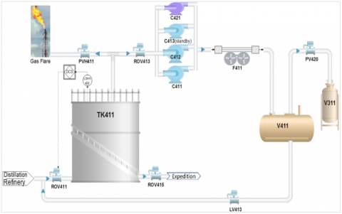
The butane refrigeration loop makes it possible to liquefy the evaporations from the butane tank. The refrigeration capacity in place makes it possible to treat the butane coming from a distillation unit and from refinery plant in the vicinity. The gaseous butane coming from the TK- tank 411 is compressed by compressors C-411, C-412 and C-413, then condensed by air condenser F-411. It should be noted that only two compressors are functioning initially, while the third is in standby. Also, in the event of an electrical failure, the C-421 compressor driven by a diesel engine allows in service the refrigeration cycle. The butane is then sent into the V-411 stabilizer balloon before being routed again to the storage tank. When the vapor phase of the V-411 balloon reaches 6.5 bars, the PV-420 opens and sends the incondensable to the V-311 expansion balloon. A simplified scheme of the TK411 is depicted in Figure 4.
The TK-411 tank is intended to store butane at approximately -8℃. In order to prevent heating due to the ambient air, the storage tank consists of a double tank and suspended roof. Heat-insulating materials occupy the space between the outer and inner walls. The characteristics of the butane storage tank are shown in Table 2.
Table 2. Characteristics of the butane storage tank
|
Tag Name |
TK-411 |
|
Service |
Butane storage tank |
|
Type |
Double wall insulated |
|
Capacity |
20.000 tons |
|
Dimension (external tanks and domes) |
D=40.7 m; h=35.7 m |
|
Design temperature |
-10℃ |
|
Design pressure |
70 mbar |
5.1.1 Level monitoring system
The storage tank is fitted with a level gauge (LS 420). The level gauge is used to give indications locally as well as in the control room (DCS/Triconex) on a recorder. It is equipped with alarms, high (LSH 420) and very high (LSHH 420), low (LSL 420) and very low (LSLL 420). When the low-level alarm sounds, the operator must immediately stop the expedition of butane. On the very low-level alarm, the loading pumps (PM 415) stop automatically to maintain a minimum volume of liquid and the withdrawal valve of the corresponding tank (ROV 415) closes. When the high-level alarm sounds, the operator must immediately stop the reception of butane, the very high-level alarm causes the automatic closing of the filling valve of the corresponding tank (ROV 411).
Safety instrumented systems associated with risk threatening the tank is presented in the following Table 3.
Table 3. SISs associated with risk threatening the tank
|
Potential Risks |
Objective of SIS |
SIS Architecture |
||
|
Detector |
Logical Unit |
Actuators |
||
|
Risk of bursting of the TK-411 tank |
High pressure safety in storage tank TK-411 |
PSH-412 |
Triconex |
ROV-451 (to close) FV-451(to close) PV-411H (to open) |
|
Risk of implosion of the TK-411 tank |
Very low-pressure Very low-level safety in the storage tank TK-411. |
PSLL-415 LSLL-420 |
Triconex |
PV-411L (to open) ROV415 (to close) + PM415 (to stop) |
|
Risk of overflowing the TK-411 tank |
Very high-level security of the TK-411 tank |
LSHH-420 |
Triconex |
ROV-411(to close) |
Table 4. Presentation sheet of the HAZOP method (Level high)
|
Deviation |
Causes |
Consequences |
Barrieres |
Criticality |
Recommendations |
||
|
Parameter |
Keyword |
S |
P |
||||
|
Level |
High |
More upstream flow. (PM411 failure) |
- Spill in the inter-wall. - Breakage of the outer wall follows from the breakage of the inner wall. - Pool fire, UVCE, Flash Fire. |
- Flow detectors (FI-414 and FI-415) allowing the operator to observe the rise in level in the tank. - High level alarm in tank TK-411 (LSH-420) + operator action. - Safety on very high level in the tank TK-411 (LSHH-420) causing the automatic closing of the ROV-411 supply valve. |
4 |
1 |
- Equip the FI-414 (or/and) FI-415 with a high flow alarm. - Install a differential pressure level transmitter, equipped with high level alarm. - Study the Safety Integrity of SIS protecting the tank against the very hight level in the tank (LSHH-420/ Triconex/ ROV-411). |
|
Human error Overfilling. |
Same as above |
Same as above |
4 |
2 |
Same as above |
||
Figure 4. Butane storage and refrigeration process [21]
According to the classification of IEC 61508, this system (On very low or very high level alarm) is called a safety instrumented system (SIS) operating in low demand: its appropriate measure of reliability is the PFD (probability of dangerous failure on demand).
In our study, we limit ourselves to the safety instrumented system (SIS) operating in the event of a very high level in the Tk-411 storage tank.
In what follows, the IEC 61508 approach will be applied on the butane storage tank described in the previous section.
6.1 Risk analysis
As we said before, the first step of the IEC61508 approach is risk analysis to identify different accident scenarios that may occur in the system to be studied (the butane storage tank). To do that, HAZOP will be used. Then, the consequences (accidents) should be expressed in terms of severity and probability (frequency) of occurrence.
6.1.1 Identification of critical accidents scenarios
HAZOP analysis method leads to identify different accident scenarios resulting from parameters deviations [22]. In our study, we limit ourselves to one deviation (‘Level high’ of butane in the tank) which can lead to catastrophic accidents, see (Table 4).
6.1.2 Selection of an accident scenario
Butane level increase in TK411 tank leads to the spillage in the inter-wall followed by a leak, causing the Pool fire phenomenon. A simulation of this scenario is presented in Figure 5.
6.1.3 Risk estimation
GL1K plant has classified risk severity levels and the occurrence frequency levels according to a scale shown in the Table 5 and Table 6 [23].
a) Estimation of the severity level
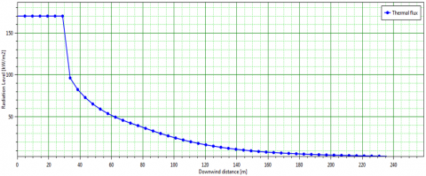
To estimate the level of severity, we modeled the thermal effects of Pool fire using the PHAST software (Figures 6-8) and compared these effects to the severity scale of GL1K [24].
The reference values relating to the thresholds of thermal effects on humans to be used are [25]:
According to the GL1K EDD [20] which defines the daily presence of personnel in zones Z1, Z2 and Z3, and referring to Table 5, the severity of studied risk (Pool fire) is "Catastrophic S4".
Figure 5. A scenario simulation
Table 5. GL1K severity scale
|
Severity |
Zone Related to Significant Lethal Effects |
Zone Related to First Lethal Effects |
Zone Related to Irreversible Effects |
|
5. Disastrous |
More than 100 exposed persons |
More than 1000 exposed persons |
More than 10000 exposed persons |
|
4. Catastrophic |
Between 10 and 100 exposed persons |
Between 10 0 and 1000 exposed persons |
Between 1000 and 10.000 exposed persons |
|
3. Important |
Between 1 and 10 exposed persons |
Between 10 and 100 exposed persons |
Between 100 and 1000 exposed persons |
|
2. Serious |
At most 1 exposed person |
At most 10 exposed persons |
Between 10 and 100 exposed persons |
|
1. Minor |
No exposed person |
At most 1 exposed person |
Less than 10 exposed persons |
Table 6. GL1K occurrence frequency scale
|
Scale |
1 |
2 |
3 |
4 |
5 |
|
Qualitative ranking |
Possible but extremely unlikely |
Very low |
Low |
Moderate |
High |
|
Frequency/ year |
F<10-5 |
10-4>F≥10-5 |
10-3>F≥10-4 |
10-2>F≥10-3 |
F≥10-2 |
Figure 6. Thermal effects vs. distance for Pool fire
Figure 7. Modeling defined thermal effects levels for Pool fire
Figure 8. Report of distance to defined thermal effects levels for Pool fire
b) Determination of the tolerable frequency
The risk matrix is a tool to classify and visualize risk by defining categories of consequences and occurrence frequency. That is, this tool is the use of both qualitative scales shown in Table 5 and Table 6. The data obtained are then applied to a matrix in Table 7, classifies different risks at different levels.
We found that the severity class for studied risk (Pool fire) is "Catastrophic S4". According to the GL1K's risk acceptance matrix, for this risk to be tolerable, the maximum tolerable frequency level should be "Very low P2", as well as, referring to Table 6, the maximum tolerable frequency should be: FT=1E-5/ year.
Risk acceptance matrix classifies different risks at different levels, as shown in Table 8.
Table 7. Risk acceptance matrix for GL1K [20]
|
|
Frequency |
||||
|
Severity |
P1 |
P2 |
P3 |
P4 |
P5 |
|
S5 |
M |
H |
H |
H |
H |
|
S4 |
M |
M |
H |
H |
H |
|
S3 |
M |
M |
M |
H |
H |
|
S2 |
L |
L |
M |
M |
H |
|
S1 |
L |
L |
L |
L |
M |
Table 8. Risk levels
|
L |
Low risk (accepted) |
|
M |
Moderate risk (tolerated) |
|
H |
High risk (not accepted) |
6.2 Allocation of the required SIL for SIS
According to IEC 61508, the SIS is the safety barrier which must put the risk in its tolerable frequency and therefore the risk in a tolerable level.
The requirements required at the SIS to carry out this mission determines the level of performance that the SIS must have (required SIL). It will be calculated using the LOPA method.
This method is an analytical tool that builds on hazard identification and characterization information developed during a HAZOP.
LOPA is widely used as semi-quantitative method for the allocation of safety integrity levels.
The factors taken into account when assigning safety requirements are the accident frequency and the tolerable accident frequency. The accident frequency needs the quantification of the initiating event frequency and the average probabilities of failure on demand of each protection layer. A major condition that must be satisfied is the independence of the different layers of protection (IPL: independent protection layers) [12].
6.2.1 Calculation of the PFDavgSIS
The PFDavg of SIS value is calculated by Eq. (1).
$P F D_{\text {avg }}^{S I S}=F_T / F_{C \text { without SIS }}$ (1)
where:
The frequency of the feared event (FC) is obtained by multiplying the frequency of the initiating event (FIE) and the average probabilities of failure on demand (PFDavgi) of each protection layer (Eq. (2)).
$F_C=F_{I E} \times \prod_i P F D_{a v g}^i$ (2)
To calculate FC without SIS, we multiply the two preceding quantities except the PFDavgSIS(Eq. (3)):
$F_{C \text { without SIS }}=F_{I E} \times \prod_{i \neq S I S} P F D_{\text {avg }}^i$ (3)
where:
Table 9. IPLs and their PFDs
|
IPL |
Appellation |
PFD |
|
IPL1 |
LAH-420 high level alarm + operator action. |
PFD1=2E-1 |
|
IPL2 |
FI-414 and FI-415 (Flow detectors) |
PFD2=1E-1 |
Applying formula (3), the accident frequency without SIS equal to: FC without SIS=2E-3/ year.
Remark: Depending on the value of the $P F D_{\text {avg}}^{S I S}$ obtained for a safety function, we deduce the corresponding SIL level by (Table 1), and which is the required SIL.
The results obtained during the application of the LOPA method are summarized in the following Table 10.
6.3 Calculation of real SIL of SIS
To calculate the SIL level of SIS, the SIL module of the GRIF software (Graphical interface for reliability forecasting) was used.
Various parameters are taken into account such as: the loop architecture integrating redundancy and voting levels, the maintenance and test policy (coverage rate and frequency), and the common cause failures "the β factor for redundant architectures is estimated at 10%".
Table 10. Summary of the results of the LOPA method
|
Security Objective FT (year-1) |
Initiating Event |
Independent Protection Layers |
Intermediate Frequency ‘Without SIS’ (year-1) |
IPL3 (SIS) |
|||
|
Designation |
Frequency (year -1) |
IPL1 |
IPL2 |
PFD |
Required SIL |
||
|
1E-5 |
EI |
1E-1 |
2E-1 |
1E-1 |
2E-3 |
5E-3 |
2 |
Table 11. Reliability data [26]
|
Equipment |
Equipment Type |
Failure Mode |
Dangerous Failure Rate λ (h-1) |
Self-diagnosis Coverage DC(%) |
First Interval Between Tests (h) |
Interval Between Two Tests Consecutive (h) |
Unit Running During Test |
Type of Testing |
MTTR (h) |
PFD |
|
LSHH-420 |
Level sensor (float) |
Does not work |
2,69E-06 |
80 |
26280 |
26280 |
non |
full |
24 |
|
|
ROV-411 |
Butterfly valve (pneumatic) |
Non-closing on request |
3,10E-06 |
70 |
26280 |
26280 |
non |
full |
24 |
|
|
TRICONX |
Safety automaton |
2.0E-4 |
||||||||
Note: The supplier has determined the PFD of TRICONX and certified it as SIL 3
a. Hypotheses:
b. Reliability data
All the reliability data to enter for the calculations we performed with the GRIF software are given in Table 11.
6.3.1 Presentation of the obtained results
The results obtained will specify for SIS:
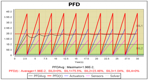
Figure 9. PFD and SIL graph of SIS
6.3.2 Results interpretation
We have noticed that in the case of a periodically tested system the probability (PFD) of having a dangerous failure between two periodic tests increases as a function of time, it increases until a test is performed and decreases just after the test has been performed, then it increases again until the next test.
The tests make it possible to verify that the components participating in the safety function are operational and, if not, to repair them.
After each test and possible repair, the components regain a probability of failure equivalent to that which they had at time t=0. ''As good as new''.
The results shown in Figure 9 allowed us to extract the SIL of the studied SIS in two ways:
1) The SIL corresponds to the SIL zone where the loop spends the greatest percentage of time. In fact, a loop with an SIL2, for example, can almost never be permanently at its SIL level over time, as shown in Table 12.
Table 12. The percentage of time spent by the loop in the different SIL levels
|
SIL |
SIL 0 |
SIL 1 |
SIL 2 |
SIL 3 |
SIL 4 |
|
The Percentage of Time (%) |
0% |
75.5% |
23.46% |
1.04% |
0% |
2) The value of PFDavg is used to deduce the value of SIL using Table 1.
Given PFDavg=1.96 E-2 and referring to Table 1: SIL (1.96 E-2) = SIL1.
Summaries of SIL calculation results are shown in Table 13.
Table 13. Summaries of SIL calculation results
|
Required SIL |
Real SIL |
Discussions |
|
2 |
1 |
Required SIL level not reached with the current configuration of the safety loop |
6.4 Validation and recommendations
By comparing the result of required SIL and real SIL (required SIL>real SIL), we deduce that SIS doesn't meets the requirements attached to it, it is therefore the risk is unacceptable.
The SIS must be optimized in such a way that the (required SIL≤real SIL) in order to reduce the risk to a level at least tolerable, we have proposed the following recommendations:
6.4.1 Result after taking into account the proposed recommendation
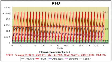
SIL result after considering the first recommendation:
Figure 10. PFD and SIL graph of SIS after considering the first recommendation
According to Figure 10, the SIL becomes SIL2.
The first recommendation makes it possible to reach the required SIL level (SIL2).
SIL result after considering the second recommendation:
Figure 11. PFD and SIL graph of SIS after considering the second recommendation
According to Figure 11, the SIL becomes SIL2.
The second recommendation makes it possible to reach the required SIL level (SIL2).
Our study focuses on the theme of the ability of an instrumented safety system to control an industrial risk, by evaluating their required performance (required SIL) and their actual performance (real SIL) according to a well-structured approach of the IEC 61508 standard.
We first presented the methodology proposed to achieve our objective. It is divided into two sections; the first presents the theory of the IEC 61508 approach, the second presents an application of this approach on an industrial system, the latter, following these steps:
This study allowed us to arrive at the results on the security state of the "TK-411 butane storage tank" system, and on the basis of these results we proposed the measures to be taken to increase the security level of the system and prevent the occurrence of adverse events. We suggest the deployment of this approach to all SIS in the complex.
[1] IEC61508. (2010). Functional safety of electric/electronic/programmable electronic safety-related systems. 2nd ed. Parts 1 to 7. International Electrotechnical Commission, Geneva. https://www.iec.ch/, accessed on Apr. 28, 2023.
[2] Omeiri, H., Innal, F. (2015). Safety integrity evaluation of a butane tank overpressure evacuation system according to IEC 61508 standard. Journal of Failure Analysis and Prevention, 15(6): 892-905. https://doi.org/10.1007/s11668-015-0031-8
[3] ISO 310000. (2018) International Organization for Standardization. https://www.iso.org/, accessed on June 12, 2023.
[4] Petryshyn, N., Mykytyn, O., Malinovska, O., Khalina, O., Kirichenko, O. (2022). Risk management system at an engineering enterprise in conditions of ensuring security. International Journal of Safety and Security Engineering, 12(4): 525-531. https://doi.org/10.18280/ijsse.120414
[5] Garzia, F. (2023). New security risk assessment and genetic algorithms based methods to optimize risk reduction countermeasures for cultural heritage sites. International Journal of Computational Methods and Experimental Measurements, 11(1): 45-54. https://doi.org/10.18280/ijcmem.110106
[6] Snorre, S. (2006). Safety barriers: Definition, classification, and performance. Journal of Loss Prevention in the Process Industries, 19(5): 494-506. https://doi.org/10.1016/j.jlp.2005.12.004
[7] IEC 61511. (2016). Functional Safety-Safety instrumented systems for the process industry sector. 2nd. International Electrotechnical Commission. Geneva, Switzerland. https://www.iec.ch/, accessed on Aug. 2, 2023.
[8] Sallak, M. (2007). Évaluation de paramètres de sûreté de fonctionnement en présence d'incertitudes et aide à la conception: Application aux Systèmes Instrumentés de Sécurité (in frensh). PhD Thesis. National Polytechnic Institute of Lorraine, France. https://hal.univ-lorraine.fr/tel-01752954/document.
[9] Lanternier, B., Adjadj, A. (2008). Allocation de niveau d’intégrité de sécurité (SIL) requis conformément a la norme CEI 61511 (in frensh). Revue internationale sur l’Ingénierie des Risques Industriels, 1(1): 34-45.
[10] Sallak, M., Simon, C., Aubry, J.F. (2006). Allocation de SIL par aggrégation d’avis d’experts. 15e Congrès de Maîtrise des Risques et de Sûreté de Fonctionnement, Lille, France, hal-00104718. https://hal.science/hal-00104718/document.
[11] Jin, J., Zhao, S., Hu, B. (2012). Defining the Safety integrity level of public safety monitoring system based on the optimized three-dimension risk matrix. Procedia Engineering, 43: 119-124 https://doi.org/10.1016/j.proeng.2012.08.021
[12] CCPS. (2001). Layer Of Protection Analysis, simplified process risk assessment. New York: IChE/CCPS John Wiley & Sons, Inc., Hoboken. https://doi.org/10.1002/9780470935590
[13] Willey, R.J. (2014). Layer of protection analysis. Procedia Engineering, 84: 12-22. https://doi.org/10.1016/j.proeng.2014.10.405
[14] Innal, F. (2008). Contribution to modelling safety instrumented systems and to assessing their performance-Critical analysis of IEC 61508 standard. PhD Thesis, University of Bordeaux, France. https://docplayer.net/.
[15] Chebila, M., Innal, F. (2015). Generalized analytical expressions for safety instrumented systems’ performance measures: PFDavg and PFH. Journal of Loss Prevention in the Process Industries, 34: 167-176. http://dx.doi.org/10.1016/j.jlp.2015.02.002
[16] Innal, F., Dutuit, Y., Chebila, M. (2015). Safety and operational integrity evaluation and design optimization of safety instrumented systems. Reliability Engineering & System Safety, 134: 32-50. https://doi.org/10.1016/j.ress.2014.10.001
[17] Omeiri, H., Innal, F., Liu, Y. (2021). Consistency checking of the IEC 61508 PFH formulas and new formulas proposal based on the Markovian approach. Journal Européen des systèmes Automatisés, 54(6): 871-879. https://doi.org/10.18280/jesa.540609
[18] Dutuit, Y., Rauzy, A., Signoret, J.P. (2008). A Snapshot of methods and tools to assess safety integrity levels of high-integrity protection systems. Proceedings of the Institution of Mechanical Engineers, Journal of Risk & Reliability, 222(3): 371-379. https://doi.org/10.1243/1748006XJRR147
[19] IMS SIS. (2020) Integrity Management Solutions of Safety Instremented System) software. Available at: https://cenosco.com.
[20] GRIF-Workshop. (2018) Graphical interface for reliability forecasting software. Available at: http://grif-workshop.com.
[21] Edraw Max software. Available at: https://www.edrawsoft.com.
[22] Dunjó, J., Fthenakis, V., Vílchez, J., Arnaldos, J. (2010) Hazard and operability (HAZOP) analysis. A literature review. Journal of Hazardous Materials, 173(1-3): 19-32. https://doi.org/10.1016/j.jhazmat.2009.08.076
[23] Jambut, R., Langlois, A., Chraibi, K. (2019). SONATRACH EDD of GL1K. Technical Document No.:1ZUAQSH-4, DNV GL France SARL Oil & Gas. https://sonatrach.com/.
[24] Process Hazard Analysis Software (PHAST) – DNV. https://www.dnv.com/software/services/phast/index.htm.
[25] Jolly, S. (2014). Omega 2 – Modélisation de feux industriels (in frensh). Technical Report DRA-76. 14. INERIS, France. https://www.ineris.fr/référentiels-feux-industriels-1424683126.pdf.
[26] Offshore Reliability Data (OREDA) Handbook. (2002). SINTEF, Trondheim. Norway. https://www.nri.ac.ir/ accessed on Oct. 8, 2023.