Giva Andriana Mutiara*![]() | Periyadi
| Periyadi![]() | Lisda Meisaroh
| Lisda Meisaroh![]() | Muhammad Rizqy Alfarisi
| Muhammad Rizqy Alfarisi![]() | Wildan Muhammad Yasin
| Wildan Muhammad Yasin![]() | Nadya Nanda Adisty
| Nadya Nanda Adisty ![]() | Muhammad Aulia Rifqi Zain
| Muhammad Aulia Rifqi Zain![]()
© 2023 IIETA. This article is published by IIETA and is licensed under the CC BY 4.0 license (http://creativecommons.org/licenses/by/4.0/).
OPEN ACCESS
In the pursuit of developing armored vehicles that offer superior safety and performance across challenging terrains, the accurate assessment of driver and passenger injury levels is critical. Currently, safety testing heavily relies on the subjective expertise of a limited number of officers. To address this limitation, we present a novel approach using a smart mannequin embedded with advanced sensor systems, emulating human-like perception. The mannequin incorporates various sensors including accelerometers, temperature sensors, as well as gas, sound, and camera sensors. Leveraging the Raspberry Pi 4B and Node MCU, we employ Internet of Things (IoT) technology to enable real-time monitoring of driver and passenger conditions within the vehicle through a web-based interface. Rigorous laboratory and field experiments were conducted to evaluate the system's performance. Our findings demonstrate the efficacy of the proposed system in monitoring smart mannequins via web applications. The alert system successfully detects gas leaks, sounds, vibrations, temperature fluctuations, and humidity levels, while also providing valuable data on speed, vibration, and position using accelerometers and GPS. Empowering smart mannequins to assume the role of humans in conducting risky tests presents a significant advancement in vehicle safety testing.
armored vehicle, field testing, injury detection, integrated sensor, Internet of Things, passenger comfort, smart mannequin, system evaluation
The defense and security industry, as well as the arms, tools, and armored vehicle product development sector, must continuously innovate in alignment with the progress of information technology and materials. A notable innovation in this domain involves the production of armored vehicles capable of operating in diverse and hazardous terrains [1]. These armored tactical vehicles serve to strengthen the primary military fleet and engage in combat effectively [2]. Constructing armored vehicles with optimal structural strength is a complex endeavor, necessitating rigorous endurance testing under real battlefield conditions. The resilience of these vehicles plays a pivotal role in minimizing casualties resulting from warfare.
Recent technological advancements have made significant strides in the realm of human modeling. Contemporary human modeling tools enable functional simulations and training for various applications [3]. Notably, the development of human modeling from the Boeman model to the Jack modeling human has introduced mannequin models with a sophisticated system of kinematic connectivity, joints, and physiological motion closely resembling the human skeletal structure [4]. Such human modeling mannequins address diverse challenges by substituting real humans with mannequins that closely resemble their structure. For instance, SAMMIE was employed to investigate design issues in tram projects, including door positions and seating arrangements [5]. Furthermore, mannequins designed for military applications have been developed to simulate the role of crew members in flying the RAH-66 Comanche helicopter [6]. Consequently, human modeling tools have proven successful in resolving various problems across numerous domains.
The proliferation of Internet of Things (IoT) technology has revolutionized remote monitoring and control, presenting limitless possibilities. IoT, as a heterogeneous communication technology, will be integrated into the future Internet and facilitate the deployment of low-cost wireless sensor networks for applications in environmental monitoring, healthcare, and agriculture [7].
Currently, the testing of armored vehicles by several companies in the country follows traditional methods, primarily focusing on passenger comfort and safety. Extensive test description essays, aligning with certification standards, meticulously document all examinations to evaluate the feasibility of armored vehicle comfort and safety. For instance, vibration testing involves measuring the vehicle's vibration by utilizing oil or water stored in a measuring vessel. Similarly, noise testing within the armored vehicle relies on manual dB noise meters and the expertise of selected engineers from the heavy vehicle innovation testing division.
To support the design of robust and reliable tactical armored vehicles for diverse battlefields and high-risk environments, the defense equipment's defense system designs require reliable driver and passenger safety considerations. Consequently, a tool is needed to assess the impact of injuries or damages sustained by drivers and passengers during attacks or encounters in hazardous terrains.
In this study, we propose the development of a human-modeling mannequin specifically designed to replicate the structural characteristics of tactical armored vehicle drivers and passengers. Human-modeling mannequins are selected due to their potential to replace human involvement in tests that are unsuitable for human participation. Notably, one such test is the examination of armored vehicle detonations or mine blast testing, which assesses the injury impact on drivers and passengers in risky environments like battlegrounds or minefields. The smart mannequin will be tailored to match the anthropometric structure of the human body and equipped with various sensors, including vibration, temperature, and gas sensors, distributed across joints and vital organs for comprehensive analysis. The entire mannequin system will be integrated with Raspberry Pi and Arduino, enabling remote connectivity via IoT technology.
The development of this smart mannequin holds promising prospects for the military industry in terms of special vehicle development, including assisting design decisions, improving vehicle robustness, ensuring driver and passenger safety, and studying the impact of factors such as warfare, challenging terrains, and bomb detonations.
The remainder of this paper is structured as follows: Section two outlines the study methodology and system design. Section three presents the testing scenarios and discusses the results. Finally, Section four concludes the paper and outlines future directions.
2.1 Research methodology
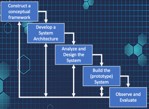
As for the method of presenting this research, it refers to the System Development Research Process method which can be seen in Figure 1. The research is beginning with the construction of a conceptual framework. It is a concept in which there are activities to investigate the functional requirements of the system derived from literature review, previous research, and observation. The overall results of literature review at this stage are collected in the form of the state-of-the-art in the next section. In addition, this stage also studies what the smart mannequin will look like, the anthropometric dimensions of the human body modeling, what sensors will be embedded in the smart mannequin, and how to interface the smart mannequin remotely.
Figure 1. System research and development method
Developing a system architecture is a collaborative design, model, and architecture development activity that will be divided in a modular manner based on system functionality. In this stage, the smart mannequin system is divided based on the mannequin assembly module, sensor attachment module on the mannequin, monitoring interface module, and data transmission media. Analyze and design the system is the stage of designing and analyzing system design based on schemes and processes that provide solutions. In this stage, the modules that have been determined in the previous stage are analyzed and started to be integrated. All of them are still in the design stage and not yet in the form of a prototype.
Next, build the prototype system. This is the stage of building a framework or model or design that is implemented in the form of a prototype. At this stage, the three modules were assembled in prototype form. The mannequin prepared in the previous stage was fabricated from Ethylene-vinyl acetate hard foam material with hinges on the neck, arms, and knees. Furthermore, a smart mannequin system interface is also integrated to communicate and monitor the mannequin's state inside the armored vehicle.
The last stages are observed and evaluated. This is the stage where the framework or model or design implemented in prototype form is tested and observed. The smart mannequin will be tested in the laboratory as well as field testing in a 6x6 amphibious-type armored vehicle. In the laboratory testing, the system will be examined with several scenarios in a closed room. Meanwhile, in the field-testing scenario, the smart mannequin will be loaded into an Anoa Amphibious 6x6 armored vehicle and travel along the test track. The test paths determined are flat track, parallel bar track, 15-degree sloping paths, and non-parallel sine paths with various wave heights. Test results are evaluated, and conclusions are drawn.
2.2 State-of-the-art the research
Modeling and simulation have played an important role in the development of modern military engineering systems and will play an even greater role in the future. The use of modeling and simulation techniques (Human Factors Engineering) allows scientists, engineers, and program managers to assess the accommodation of the intended user population by system design early and continuously throughout the system life cycle [6]. This technique can also help reduce time and costs also reduce the risk for human system integration (HSI). In the case of HFE and HIS, it is used to assess ergonomic design requirements, mental and physical workload, workforce requirements, and areas related to HSI.
Human figure modeling analysis consists of several components that are integrated into the 3D graphics capitalization environment. This component includes 3D data such as human figure models and associated anthropometric data for the target population to be accommodated, clothing, equipment models, posture data, and possibly motion capture data. Often, analysis using human figure models is carried out with naked body models. While the clothes can be ignored. But for some activities, clothing is one of the conditions that must be considered, because sometimes it has an impact on the performance of the operator. Nuclear warfare, biological warfare, protective helmets, and armor are among the virtues that can be added to the mannequin [8].
This research develops traditional mannequins’ technology which is often used in various research fields. Traditional mannequins will be developed into smart mannequins based on modern human modeling. This mannequin is made to resemble the structure of a real human body with joints, weight, and body postures that also resemble humans.
At the beginning when CAD software was available, digital human modeling tools appeared in the late 1960s in the automotive and aviation industries [9]. The first digital man was developed by Boeing in the late 1960s to assess pilot accommodation in the cockpit of an airplane, known as the Boeman. This Boeman has 23 joints with unchangeable depth and segment width which was a drawback of the Boeman, as the entire joint was made permanent. In 1970, cybernetics was developed by the Chrysler Corporation to design and evaluate automobiles. The mannequin consists of 15 segments of various sizes needed but the mannequin does not have joint constraints. Therefore, this is a weakness of the mannequin because it has no joints. The mannequin must be taken care of when occupying the mannequin [10].
In 1990, MannequinPro was created which is a PC-based human modeling tool that can create male and female models based on 11 survey populations including NASA data. This mannequin has a realistic range of motion. This mannequin is used by the air operation division to assist in evaluating the fields of view of the pilot and load master on the S-70A-9 Black Hawk helicopter [11]. This MannequinPro can only measure ergonomic design and realistic range of motion, but cannot measure other comfort parameters besides physical form factor.
SAMMIE was used to investigate a number of design issues for the STIB Tramway 2000 tram project. SAMMIE was used to assess potential ergonomic issues. SAMMIE uses mannequins of various sizes, for the ergonomics of the TRAM driver [10]. While development of Jack's powerful human modeling tool began in the mid-1980s at the Center for Human Modeling and Simulation at the University of Pennsylvania. The primary impetus for Jack's development was to support the design and development of workspaces, with an emphasis on optimizing the human-machine interface for specific populations. Jacks is also similar to MannequinPro and SAMMIE in that it is made to support ergonomic design without involving other sensors to detect the surrounding area.
In 2002, the mannequin was embedded with a thermal sensor to measure the driver’s temperature while driving a car. In this mannequin, a temperature sensor has been involved in measuring the room temperature in the car. This research aimed to measure the comfort experienced by humans in a given environment inside a car [12]. However, the mannequin still has a weakness where the temperature measurement is still not integrated with the monitoring system. This system did not use the Internet of Things to be monitored remotely.
In 2020, a model of human head injuries in an armored vehicle has been studied to predict the head injuries of soldiers in an armored vehicle as a passenger. Unfortunately, this study has weaknesses because only focuses on the 3D modeling of various head injuries and does not focus on the injuries in the real condition.
In the meantime, IoT technology is also increasingly playing a role in applications or systems that involve monitoring. The trend of involving IoT technology is because IoT can observe outreaching areas that need monitoring from a safe distance radius. In addition, IoT is a collaborative linkage technology between embedded systems and the internet that revolutionizes things and the internet. Nearby monitoring parameters can be identified and become important and smart data that is also used to analyze context-related decisions and transmit the information to other devices via the internet [13].
A lot of IoT is also utilized to monitor safety driving. By placing sensors around the monitoring area, a system can detect the monitored parameters and send the information over the IoT. One of them is monitoring safety vehicles that supervise driver safety by placing sensors that can identify the psychological characteristics of the driver [14]. IoT has also been applied to systems that detect traffic violations such as speed vehicles, over-capacity passengers, and unfastened seat belts, thereby improving the safety factor of drivers and passengers [15]. In addition, IoT has also been used to monitor safety-based travel routes by taking into account the parameters of the road conditions that will be traveled by the driver [16].
Based on the description above, the existing human modeling as a mannequin mostly focuses on the ergonomic side of a vehicle to ensure the comfort of passengers or drivers. Many of them are not equipped with integrated sensors that function to detect environmental conditions around the mannequin. In addition, continuous active control of the mannequin system has not been applied to existing mannequin systems.
Therefore, with the development of IoT technology and embedded systems, this research will develop a smart mannequin with various sensors embedded in it [7]. Hence, a mannequin modeled as a soldier in an armored vehicle can be monitored remotely. The condition of the passengers and driver can be activated and controlled continuously.
2.3 Smart mannequin designed system
Smart mannequin is a system designed to provide solutions for detecting the impact of damage or injury or the level of safety for IoT-based defense equipment drivers. Smart mannequins can be utilized and are closely related to the toughness of armored vehicles, driver safety, and ergonomic aspects.
This system is consisting of three modules. The first module is mannequin design module, the second module is embedded sensors module, and the third module is the monitoring module.
The mannequin design modules are designed from fabricated thick Ethylene-vinyl acetate foam material following the Indonesian human postures that working as a soldier in the military field, which range from 165-170 cm in height [17]. This is because most armored vehicles are used by troops in various missions. The mannequin has nine hinges attached to move the legs and arms as seen in Figure 2. The nine hinges mounted on the mannequin's limbs facilitate the positioning of the mannequin while seated in the armored vehicle.
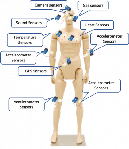
The embedded sensor modules are designed with several sensors that will be attached in the mannequin. The sensors installed to the mannequin occupy the position of the human vital organs and include the five human senses. The mannequin head consists of a camera sensor, sound sensor and gas sensor. The camera sensor functions as an eye sense, a vision sensor that can see the environment around the mannequin. The gas sensor is an olfactory sensor that can sense the smell of gas around the mannequin. While the sound sensor functions as an auditory sensor that can feel the sensation of sound which will be associated with the heart sensor.
Then, on the body module, installed a temperature sensor that functions to sense the temperature around the mannequin, and a sensor that functions as a heartbeat, by utilizing the alarm sensor which is set according to a normal human heartbeat. A GPS sensor is also attached to the body of the mannequin which can provide information about the position of the mannequin.
Meanwhile, on the feet and hands of the mannequin, each accelerometer sensor is attached, which can detect vibrations generated where the mannequin is. In addition, this sensor serves to provide information when the leg or hand is broken or detached from the body. All the embed sensor can be seen in Figure 3.
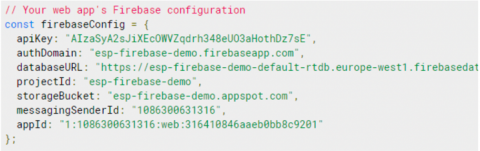
The monitoring module is designed in web based and serves the monitoring the performance of all sensors. All data sensors are designed with Application Programming Interface (API) and utilize the IoT technology. For the monitoring module, the next step is to configure firebase account and getting the API key path as seen in Figure 4. The picture shows the use of the API key path, the authDomain, the databaseURL and the projectid that has been addressed by the system.
Figure 2. Smart mannequin design structure
Figure 3. Embedded sensors on smart mannequin
Figure 4. Firebase account
The data detected on the sensor is sent by Raspberry pi via ESP-32 and received by Firebase. Furthermore, it will translate in the form of API key, databaseURL, and projectid as shown in Figure 5.
Finally, to make it easier to monitor the sensors attached to the mannequins in the armored vehicle, all the data sensors will be displayed on the web monitoring that designed as seen in Figure 6. Information is displayed in the form of numbers and graphs.
Figure 5. Firebase program
Figure 6. Website display
Figure 7. Smart mannequin system
Figure 8. Flowchart system
All the modules (smart mannequin, sensor, and monitoring module) are integrated and showed in Figure 7. As can be seen in Figure 7, the mannequin is embedded with several sensors and located in the armored vehicle. Then all the sensors will send all the data sensors to the raspberry pi and controlled by the IoT system. Thus, the condition of the mannequins in the armored vehicle can be monitored continuously.
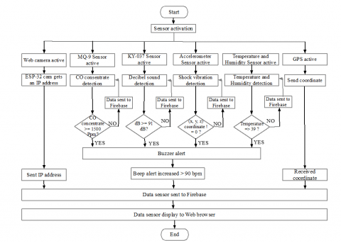
Based on the description of the proposed system design above, the flowchart of the smart mannequin system can be seen in Figure 8. The system begins by activating all sensors connected to the mannequin. The MQ-9 gas sensor, the KY-037 sound sensor, temperature sensor, and the accelerometer sensor will detect the environment according to the characteristics of each sensor. While the web camera will be active and get an IP address that will be sent to firebase. As well as the GPS sensor which starts by detecting the mannequins’ position coordinates and sending the coordinate values to firebase.
The buzzer as an artificial heartbeat is set at 75-90 bpm to resemble the human heartbeat rate. The heart rate will provide an alert if the sensor detects an activity that is exceeding the allowable threshold. If the MQ-9 gas sensor, the KY-037 sound sensor, the temperature, and the accelerometer sensor find data that exceeds the allowable threshold, the buzzer will give an alarm alert faster than 91 bpm [18].
All detected sensor data will be transmitted to Firebase. Firebase will then translate all the data and display the values and graphs on the web browser.
The experiments were conducted to test the system’s performance. The experiment is carried out with various kinds of scenarios including testing the performance of the MQ-9 sensor, KY-037 sensor, accelerometer sensor ADXL345, tracking the mannequin’s position, and testing the web camera’s performance angle taken on the mannequin’s eyes. The sensors are placed in such a way that they are on the mannequin’s body as shown in Figure 9.
In Figure 9, the web camera sensor is placed in the mannequin’s eye. The sound sensors are placed on the right and left side of the mannequin’s ear, the gas sensor is placed in the area of the mannequin’s nose, the beep alarm is placed on the left chest of the mannequin. Meanwhile, the GPS is placed above the alarm beep sensor, and the accelerometer sensors are placed on the right and left hands of the mannequin.
Figure 9. Smart mannequin for testing laboratory
3.1 Mannequin sensor performance testing
Mannequin sensor testing is carried out with the aim to test how robust the sensors attached to the mannequin can sense the environment. The first experiment is the MQ-9 sensor test. The MQ-9 is a sensor that has the ability to detect CO gas at low power sources and detect methane gas at high power sources. Hazardous gases such as methane (CH4), and carbon monoxide (CO) will have adverse effects on humans as they can cause explosions and CO poisoning accidents in most risky terrains. The test is carried out in a closed laboratory room (ignoring the wind and the spacious room) as seen in Figure 10.
Figure 10. MQ-9 sensor test scenario
Table 1. MQ-9 result test
|
Distance |
Result |
Alarm |
|
10cm |
Detected |
Alert |
|
15cm |
Detected |
Alert |
|
20cm |
Detected |
Alert |
|
25cm |
Detected |
Alert |
|
30cm |
Undetected |
No Alert |
The test result can be seen in the table shown in Table 1. As shown in Table 1 above, the mannequin can sense the smell of gas from a distance of 25cm, while at a distance of 30cm, the alarm will no longer give an alert. MQ-9 sensors were tested against methane gas and carbon monoxide gas. In addition, the temperature and humidity at the time of gas testing were monitored at 27℃ with a humidity of 50.3%.
The second experiment is the accelerometer sensor test. The accelerometer used is the ADXL 345. The accelerometer was tested under field testing conditions inside the armored vehicle type ANOA 2 Amphibious 6×6. The test is carried out in an armored vehicle with a low speed of under 20 m/s in four track fields: Flat track, parallel bar track, sine-wave track, and sloping track. The resulting test can be seen in Table 2. It shows that the accelerometer works according to the terrain of the track it is traveling on. The result stated that the accelerometer sensor can detect the mannequin’s speed and transfer into position degrees shown in Figure 11. The angle was generated to measure the stability of the mannequin's position on the four tracks tested.
In Figure 11, the X, Y, and Z parameters in Table 2, are mapped with the sitting position of the mannequin inside the Armored vehicle. As seen in Table 2, column Z (m/s), the smallest passenger vibration is obtained when the Armored vehicle is on a flat track with a movement angle of 1.4°, on a parallel bar track the movement angle of the smart mannequin body vibration is at a position of about 5°. While on the sine-wave track, the angle of vibration movement is obtained at 10°, while on the sloping track is a condition where passengers are burdened with a slope angle of 15°.
The third experiment is the KY-037 sensor test. The test aims to get the sound sensor performance. The test is carried out in a quiet and bustle closed laboratory room. The resulting test can be seen in Table 3. Based on the test results, the sound produced above 90dB will be categorized as low sound while the sound produced above 91dB will be categorized as an alert alarm [19]. This is because the ability of the human ear is limited, therefore, too much noise that is heard for a relatively long time can have a negative impact on hearing.
Table 2. Accelerometer ADXL-345 result test
|
Context |
X (m/s) |
Y (m/s) |
Z (m/s) |
Degrees (o) |
|
Flat track |
7.38 |
10.21 |
-0.35 |
1.4 |
|
Parallel bar track |
5.503 |
7.75 |
-1.183 |
5 |
|
Sine-wave track |
3.14 |
5.89 |
-1.85 |
10 |
|
Sloping track |
5.38 |
10.06 |
-3.16 |
15 |
Figure 11. Accelerometer mapping into coordinate
Table 3. KY-037 sensor result test
|
Sound Sensor (dBm) |
Distance |
Result |
Class Categorized |
|
Sound<90 |
5cm |
Detected |
Low Sound |
|
20cm |
Detected |
||
|
30cm |
Detected |
||
|
50cm |
Detected |
||
|
70cm |
Detected |
||
|
Sound>91 |
5cm |
Detected |
Alert |
|
20cm |
Detected |
||
|
30cm |
Detected |
||
|
50cm |
Detected |
||
|
70cm |
Detected |
||
|
100cm |
Detected |
Table 4. GPS result test
|
Context |
Capture Coordinate |
Google Map Coordinate |
Deviation |
|
In the Armored vehicle |
-6.9308783, 107.64861 |
-6.9308108, 107.64892 |
28.34 meters |
|
In the open area of Telkom University |
-6.973331, 107.6320101 |
-6.9734661, 107.6319082 |
18.44 meters |
|
In the laboratory room |
-6.9734674, 107.6324554 |
-6.9731017, 107.6325237 |
37.91 meters |
Table 5. Web cam result test
|
Context |
Point of View (Degree) |
Result |
|
In the Armored vehicle |
45 |
|
|
In the laboratory room |
45 |
|
The fourth and fifth experiment is the GPS sensor test and web camera sensor. The test is carried out in an Armored vehicle, in the open area of Telkom University, and in the laboratory. The resulting test can be seen in Table 4 and Table 5.
Based on the test results on Google map and on the GPS system, it can be stated that there is a deviation in distance from the mannequin’s actual position in a closed room inside the building, which is 38.91 meters, while in the armored vehicle, there is a mannequin deviation position of 28.34 meters. Meanwhile, the deviation of the mannequin position in an open area is only 18.44 meters.
Based on the test result of the web camera, the camera must be provided with sufficient lighting. Therefore, it can provide good video quality. In armored vehicles, lighting is added by installing sufficient lighting (LED lamp), so the camera can provide moving images properly. Meanwhile, temperature experiment is not carried out in the laboratory, due to the stability of the surrounding area. Temperature sensors will be very useful for determining the temperature inside the armored vehicle. In addition, the temperature sensor can also be used to determine the room temperature of an armored vehicle during the explosion test (if necessary). The temperature sensor experiment is carried out in the second test together with the field experiment. The allowable temperature is 39 degrees [20].
3.2 System and monitoring module performance test
Furthermore, the experiment is to test the integrated system and monitoring module. The field-test road can be seen in Figure 12.
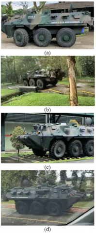
The test was carried out as a field test on an armored vehicle type ANOA 2 Amphibious 6x6. with flat track Figure 12(a), sine wave track Figure 12(b), parallel bars track Figure 12(c), and sloping track of 15 degrees in Figure 12(d). The system will be tested with various speed variations from 10 to 40 km/h for flat track, parallel bar track, and a sloping track. Especially for the sine-wave track, it can only be attempted up to a speed of 20 km/h, due to the steep track terrain.
Integrated testing correlates with sending existing sensor data from the mannequin body to the Firebase cloud. The communication media between the transmitter and receiver uses WiFi signals. The use of Firebase is conducted to store the data obtained from the test results and create a special Application Programming Interface (API) to keep the parameters that are sensed by the sensor. Meanwhile, testing the monitoring display is performed by publishing the public domain therefore it can be easily accessed and analyzed remotely from the monitoring base. The concept of integrated flow data monitoring can be seen in Figure 13. Whereas the web monitoring display can be seen in Figure 14.
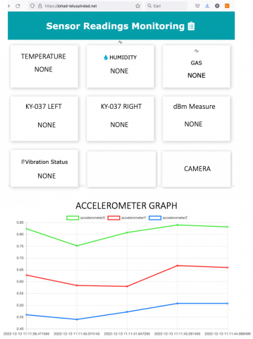
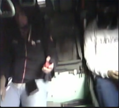
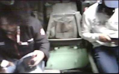
The web display testing is in Figure 14 shows the display of sensor readings monitoring on a mannequin while taking field experiments. The test results show that data sensors can be monitored through the web-based application.
The sensor reading monitoring displays information about temperature, humidity, gas, noise (KY-037), dB meter measurement, vibration status, accelerometer graph, and camera sensor. Monitored data can be received in real-time conditions. The response time data changes, received in an average of 5 seconds depending on the weather and connection.
The result of the integrated system performance can be seen in Table 6. Table 6 shows that the sensor test results listed on the smart mannequin body are temperature, KY-037, MQ-9, heartbeats, ADXL345, alarm alert, and camera display. The test results will show how accurately the alert system responds. In the alert system design, the alarm will work depending on the threshold of each sensor. The alert alarm system is set to turn on if the KY sensor is more than 91dBm, the gas sensor is at 1500 ppm, the temperature is 39°, and the coordinates of body movement are more than 25°. The determination of the threshold is as Value, that if a human being is in a condition exceeding the situation can affect the health and possible disability that may occur if it continues to be left unattended. However, the heartbeat sensor has no effect on the triggering of the alert system.
Figure 12. Field test track at (a) flat-track, (b) sine-wave track, (c) parallel bars track, (d) sloping track
Table 6. The integrated system performance at field experiment
|
Road |
Speeds (m/s2) |
Temperature (℃) |
KY-037 (dBm) |
MQ-9 (ppm) |
Heartbeats (bpm) |
ADXL 345 (Degrees) |
ALARM |
WEB CAM |
|
Flat track |
10 |
27 |
75 |
300 |
93 |
19 |
OFF |
VERY CLEAR |
|
20 |
80 |
95 |
10 |
OFF |
||||
|
30 |
85 |
96 |
20 |
OFF |
||||
|
40 |
93 |
98 |
14 |
ON |
||||
|
Parallel bar |
10 |
28 |
100 |
329 |
92 |
13 |
ON |
CLEAR |
|
20 |
90 |
93 |
23 |
OFF |
||||
|
30 |
98 |
100 |
6 |
ON |
||||
|
40 |
102 |
96 |
30 |
ON |
||||
|
Sloping track |
10 |
25 |
78 |
297 |
93 |
15 |
OFF |
CLEAR |
|
20 |
85 |
95 |
17 |
OFF |
||||
|
30 |
90 |
93 |
15 |
OFF |
||||
|
40 |
100 |
92 |
11 |
ON |
||||
|
Sine wave |
10 |
25 |
90 |
355 |
98 |
20 |
OFF |
UNCLEAR |
|
20 |
99 |
103 |
27 |
ON |
Figure 13. Integrated flow data monitoring
Figure 14. Web display testing
On the flat track, there was one alert that occurred when the ANOA 2 amphibious 6×6 was at a speed of 40. The sound sensor detected the roar of the engine sound reaching 93 dB, hence the alert system activated. On the parallel bar track, there were three alerts caused by the KY-037 sensor threshold and ADXL position reaching 30°. On the sloping track, there was one alert when the Anoa 2 amphibious 6x6 was at a speed of 40 and caused a noise of 100dbm, and triggered the alert system. Meanwhile, for the sine-wave track, the alert system was also triggered once due to the vibration of the ADXL sensor and KY-037 sensor exceeding the threshold.
Meanwhile, the image capture results on the camera show that on the flat track, the condition inside the explored vehicle can be monitored very clearly, as well as on the parallel bar track and sloping track. Camera monitoring in unclear conditions is obtained when the armored vehicle is on a sine-wave track, where the track has different heights and causes vibrations to the monitoring inside the armored vehicle.
This research was conducted to assist the military industry in measuring the safety level of armored vehicles for passengers and drivers. Currently, the smart mannequin system has been successfully experimented on the ANOA II Amphibious 6×6 armored vehicle and monitoring smart mannequins in various test fields. The smart mannequin system was also effectively monitored through a web-based display with a response time of 5 seconds. The alert system test works properly according to the applied threshold value. Thus, the smart mannequin can help the military field in monitoring the safety and comfort of its armored vehicles. In addition, smart mannequins can also be used for mine blast testing and tests that are risky to replace human roles. The system has limitations in the connection between the smart mannequin and the control center, and this can be further developed in the future. In addition, this system will be better if it develops the correlation of sensors with artificial heartbeat so that it really complies with actual human modeling.
For future work, the smart mannequin can be constructed with latex materials. In addition, Hinge structures can be added in several mannequin’s bodies such as waist hinges wrist hinges, or legs, therefore the smart mannequin becomes dynamic and maneuvers like a human body structure. Meanwhile, the communication system can be added using radio frequency such as 6LoWPAN or LoRA, so that it can be properly monitored in areas that are not covered by WI-FI.
We would like to express my appreciation to Directorate General of Vocation Education, Ministry of Education, Research and Technology of the Republic of Indonesia. We also thank you to Directorate of Research and Community Service (PPM) Telkom University and to Embedded and Network System Research Group Laboratory of Telkom University, Bandung, Indonesia for supported this research. This research received publication funding from Directorate General of Vocation Education, Ministry of Education, Research and Technology of the Republic of Indonesia DRPM, in domestic applied scientific research program grants for lecturers of vocational universities for the 2022 fiscal year with contract number 406/PNLT3/PPM/2022.
[1] Rustandi, A., Suprianto, A., Pramana, N. (2014). Performance evaluation of medium tank Indonesia to comply with military's technical specification. eJournal BPPT, 193-202.
[2] Pindad, P. (2016). Peralatan militer produk ketahanan dan keamanan. https://pindad.com/alkapsus.
[3] Blanchonette, P. (2010). Jack human modelling tool: A review. Defence Science and Technology Organization, 1-37. http://www.dtic.mil/dtic/tr/fulltext/u2/a518132.pdf.
[4] Norris, G., Brown, A.S. (2015). Role models. Aviation Week and Space Technology, 177(17): 38-39.
[5] Porter, J.M., Freer, M., Case, K., Bonney, M.C. (1995). Computer aided ergonomics and workspace design. In Evaluation of Human Work: A Practical Ergonomics Methodology, 2nd Edition, Edited by J R Wilson and E N Corlett, Taylor & Francis,London, pp. 574-620,
[6] Hicks, J.S., Durbin, D.B., Kozycki, R.W. (2010). An overview of human figure modeling for Army aviation systems. Army Research Laboratory Technical Report.
[7] Khan, Z.A., Abbasi, U. (2016). Evolution of wireless sensor networks toward internet of things. Emerging Communication Technologies Based on Wireless Sensor Networks: Current Research and Future Applications, 179-200. https://doi.org/10.1201/b20085-16
[8] Sya’bana, Y.M.K., Sanjaya, K.H. (2017). Camouflage design and head measurement characteristic of Indonesian armoured vehicle helmet. AIP Conference Proceedings, 1788(1): 030075. https://doi.org/10.1063/1.4968328
[9] Sinclair, I.R. (2001). Sensors and Transducers. Third Edition.
[10] Porter, J.M., Case, K., Bonney, M.C. (1990). Computer workspace modelling. In Evaluation of Human Work: A Practical Ergonomics Methodology, Editors J.R. Wilson and E.N. Corlett, Taylor & Francis, London, pp. 472-499.
[11] Yogasara, T. (2004). The use of computer aided design (catia v5 r8) for ergonomics analysis. Prosiding Seminar Nasional Ergonomi, 2: 356-364.
[12] Da Silva, M.G. (2002). Measurements of comfort in vehicles. Measurement Science and Technology, 13(6): R41. https://doi.org/10.1088/0957-0233/13/6/201
[13] Iqbal, A., Rana, M.E. (2019). Adoption of IOT in automobiles for driver’s safety: Key considerations and major challenges. International Journal Of Scientific & Technology Research, 8(09): 1378-1384.
[14] Wang, Z.H., Horng, G.J., Gwo-Jia, J. (2021). A vehicle safety monitoring system based on the Internet of things and the identification of physiological characteristics. Computers & Electrical Engineering, 89: 106946. https://doi.org/10.1016/j.compeleceng.2020.106946
[15] Daraghmi, Y.A., Helou, M.A., Daraghmi, E.Y., Abu-Ulbeh, W. (2022). IoT-based system for improving vehicular safety by continuous traffic violation monitoring. Future Internet, 14(11): 319. https://doi.org/10.3390/fi14110319
[16] Taha, A.E.M. (2018). An IoT architecture for assessing road safety in smart cities. Wireless Communications and Mobile Computing, 2018: 1-11. https://doi.org/10.1155/2018/8214989
[17] Dewi, A.K., Antropologi, D. Ukuran-Ukuran antropometris pada prajurit TNI AD yonif linud 503/mayangkara (Perbedaan Antara Kelompok Prajurit Yang Mengikuti Pleton Tangkas Dengan Prajurit Yang Tidak Mengikuti Pleton Tangkas). https://repository.unair.ac.id/79403/3/JURNAL_Fis.ANT.30%2018%20Dew%20u.pdf.
[18] Avram, R., Tison, G.H., Aschbacher, K., Kuhar, P., Vittinghoff, E., Butzner, M., Runge, R., Wu, N., Pletcher, M.J., Marcus, G.M., Olgin, J. (2019). Real-world heart rate norms in the health eHeart study. NPJ Digital Medicine, 2(1): 58. https://doi.org/10.1038/s41746-019-0134-9
[19] Sayapathi, B.S., Su, A.T., Koh, D. (2014). Mean hearing threshold levels upon adopting 85 and 90 dba as permissible exposure limits over six months. World Applied Sciences Journal, 30(30): 205-213. https://doi.org/10.5829/idosi.wasj.2014.30.icmrp.27
[20] Ungar, E., Stroud, K. (2010). A new approach to defining human touch temperature standards. In 40th International Conference on Environmental Systems, p. 6310. https://doi.org/10.2514/6.2010-6310