Nasser Dine Hadj Djelloul* | Mohamed Djermane | Noor Sharari
© 2020 IIETA. This article is published by IIETA and is licensed under the CC BY 4.0 license (http://creativecommons.org/licenses/by/4.0/).
OPEN ACCESS
The elevated water tanks are high importance structures for the humanity lifelines. These elevated tanks are considered as very sensitive structures for seismic movement conditions. Among the reasons for the damage and failure of elevated tanks is the design of its support systems. For this reason, several theoretical and experimental researchers studied the performance of this type of structure under seismic loading. The present study aims to demonstrate the supporting system effect on dynamic buckling of the elevated water tank, using three dimensional finite element technique the seismic response of two elevated water tanks was established taking into account the following factors; the fluid-structure Interaction (FSI), the wall flexibility, different nonlinear time histories analysis, and the material and geometric nonlinearity. Indeed, the application of three different instability criteria for the critical PGA estimate using two seismic excitations, namely El Centro and San Fernando earthquake. The numerical values are compared and no significant effect is found of the supporting system for convective fundamental frequency; however, strongly disturbed impulsive fundamental frequency. In addition, the effect of supporting system and the frequency content of the earthquake on PGAcr are clearly shown. A percent increase of PGAcr can reach up to 37.48%.
tank staging, nonlinear analysis, finite elements, seismic, dynamic buckling, fluid–structure interaction
Storage tanks are important means used mainly to store water (for daily life use), and hydrocarbon (for industrial use). These tanks constructed in a different shape mainly rectangular and cylindrical. Cylindrical tanks are the most commonly used because they have a simple design and more functional when it comes to the load’s resistance. These elevated tanks are supported on steel or reinforced concrete systems to provide self-pumping from the force of gravity. In addition, the elevated tanks ought to function in the seismic location after earthquakes to maintain the water supply during and after the earthquake. Environmental pollution can be result if the nuclear power plants and oil industry tanks are leakage, which created catastrophic results when they were damaged and totally fell down.
For example, the earthquakes in Alaska 1964, Niigata 1964, Parkfield 1966, San Fernando 1971, Miyagi prefecture 1978, Imperial County 1979, Coalinga 1983, Northridge 1994, Asnam 1980 and Koaceli 1999 demonstrated the same noticeable damages [1].
In terms of seismic analysis and modelling, many researchers have studied the dynamic behavior of elevated tanks. Housner [2] allowed the engineers to perform the analysis of the seismic responses of the elevated rigid tanks by using the two-mass analytical method. The liquid was assumed to be incompressible and inviscid; this analytical model has been adopted in many codes for it is simplicity and accuracy.
The dynamic behavior of rigid Intze tanks was investigated by Joshi [3]. The results of the model were evaluated and compared to those of equivalent cylindrical tanks. The fluid was assumed to be non-viscous and incompressible. Analyses indicated that the difference between the results obtained from intze tank and the equivalent cylindrical tank were negligible.
Dutta et al. made a comparison between raised tanks support systems and proposed approximate empirical equations for evaluating the lateral, horizontal and torsional stiffnesses for different support systems [4-6]. Shrimali and Jangid investigated two types of isolated tank models in which the bearings are placed at the top and base of the steel tower [7].
Livaoglur and Dogangun [8] studied the effects of soil-structure interaction on the seismic behaviour of the elevated tanks with a structural frame supporting system. It was concluded that the soil-structure interaction effect has significant impacts on the shear stress, overturning moments, axial forces and lateral displacement.
Moslemi et al. [9] studied the performance of elevated tanks under seismic excitations. In this study, the analysis of free vibrations is carried out on models. The response of rigid and flexible models with different basic conditions which are fixed and articulated under the two horizontal and vertical components of the earthquake are obtained using the direct integration method. It was concluded that there is a very good agreement between current practice and the finite element method in seismic analysis.
Leonard et al. [10] evaluated the buckling capacity using finite element technique. In this paper the analysis used provide powerful tools for estimating buckling modes and evaluating the effects of stiffener arrangements.
Malhothra et al. [11] proposed simplified theoretical calculation tables for seismic design of ground-supported cylindrical tanks. The procedure takes into account both impulsive and convective components.
Algreane et al. [12] studied a method to add the impulsive mass to the walls of tanks alternative to Westergaard approach. They simulated six models approach distributed masses to determine the fundamental period. The results showed that the distribution did not significantly affect the dynamic analysis of elevated tanks.
Shakib et al. [13] investigated the filling level of the tank supported by a moment-resisting frame by using FE analysis subjected to horizontal seismic excitations. Their findings indicated that the maximum response does not always occur in the full tank case.
Sweedan [14] investigated the effect of vertical earthquake excitation on the dynamic behaviour of elevated tank and propose a simplified equivalent mechanical model. It has been shown that the vertical excitation of these tanks can cause a significant increase in compression stresses generated in the walls of the tanks. Furthermore, Chaduvula et al. [15] investigated an experimental model of cylindrical steel elevated water tank subjected to combined horizontal, vertical and rocking motions. The main conclusions they found; there is not much rocking effect from the base on sloshing by visual observation and pressure on the tank walls due to vertical excitation increases with increasing excitation.
The Damages caused by past earthquakes showed the importance of the supporting system for the elevated tanks. Jabar and Patel [16] made a comparison between basic staging patterns, staging with radial bracing and staging with cross bracing. They studied the effect of this supporting staging on the base shear, bending moment and displacement of the elevated concrete tank under different earthquake time histories using Sap2000 software. In the same subject, Vyankatesh and Varsha [17] considered the effect of supporting staging on the dynamic behaviour of elevated concrete tanks with various fluid levels in different seismic zones. In a recent study published by Pole and Khedikar [18] three different types of supporting systems were analysed with different capacities of the tank, and they made a comparison between displacement and base shear of each supporting system.
Shell Buckling mode is one of the most common forms of damage in steel tanks generally classified as elastic buckling ‘’ diamond shape ‘’ and elasto-plastic buckling ‘’elephant foot’’, as shown in Figure 1. This instability appears usually around the bottom of tanks. For this reason, many several theoretical and experimental research studies were performed such as Liu and Lam, Nagashima et al., Virella et al. and Djermane et al. [19-22].
On the basis of previously-mentioned research, we can say that it is found that nearly all the published literature discussed the dynamic buckling of the tank and relationship between the dynamic behavior of the elevated water tank with the supporting system. However, there were no studies for the impact of the supporting system on the dynamic buckling of elevated water tanks.
The aim of this study is to investigate the effect of supporting system and the frequency content of the earthquake on dynamic buckling of elevated water tank, which will lead to a clarification and understanding of the dynamic behavior of elevated water tank under seismic excitation. This work is also motivated by the need for the enhancement of Algerian seismic code (RPA99/2003) which does not contain any provisions for liquid storage tanks design yet.
Figure 1. (a) Collapse elevated tank 1980 El-Asnam earthquake [23], Algeria; (b) Elephant foot buckling [24]
In order to understand what is behind the various international codes, a brief review of codes is presented in this section and they are used to validate the finite element model in the following sections.
Many current codes such as Eurocode-8 [25] employed Veletsos and Yang’s model [26] for determining the dynamic behaviours for the rigid circular tanks and Veletsos [27]; Haroun and Housner [28] for the flexible circular tanks with the approach proposed by Malhotra et al. (2000) Table 1. The American Concrete Institute ACI 350.3-06 [29], the American Water Work Association AWWA [30], and the American Petroleum Institute API 650 [11] codes employed the Housner’s mechanical model [2] with some modifications for determining the dynamic behaviours of the liquid in a container. According to Euro code-8 (2003); the parameter should be calculated using the following equations [Eq. (1) to Eq. (5)]:
$k_{c}=m_{c} \frac{g}{R} 1.84 \tanh \left(\frac{1.84 h}{R}\right)$ (1)
$m_{c}=m_{e} \frac{R}{h} 0.318 \tanh \left(\frac{1.84 h}{R}\right)$ (2)
$h_{c}=\left[1-\frac{\cosh (1.84 h / R)-1}{1.84 h / R \sinh (1.84 h / R)}\right] h$ (3)
$\mathrm{m}_{\mathrm{i}}=\mathrm{m}_{\mathrm{e}} \frac{\tanh (1.74 \mathrm{R} / \mathrm{h})}{(1.74 \mathrm{R} / \mathrm{h})}$ (4)
$h_{i}=\frac{3}{8} h$ (5)
where, h, R, kc, mc, mi, me et hc are the fluid height, radius tank, convective rigidity, convective mass, impulsive mass, total mass and convective Hight.
Then, a more simplified approach was elaborated by Malhotra et al. This spring-mass model is used in Eurocode 8 (2003) (Table 1) [11].
Table 1. Recommended design values for the first impulsive and convective modes of vibration [11]
|
HL/R |
Cc |
mi/mw |
mc/mw |
hi/HL |
hc/HL |
|
0.3 |
2.09 |
0.176 |
0.824 |
0.400 |
0.521 |
|
0.5 |
1.74 |
0.300 |
0.700 |
0.400 |
0.543 |
|
0.7 |
1.60 |
0.414 |
0.586 |
0.401 |
0.571 |
|
1 |
1.52 |
0.548 |
0.452 |
0.419 |
0.616 |
|
1.5 |
1.48 |
0.686 |
0.314 |
0.439 |
0.690 |
|
2 |
1.48 |
0.763 |
0.237 |
0.448 |
0.751 |
|
2.5 |
1.48 |
0.810 |
0.190 |
0.452 |
0.794 |
|
3 |
1.48 |
0.842 |
0.158 |
0.453 |
0.825 |
The natural periods of the convective (Tc) responses is:
$T_{C}=C_{C} \sqrt{\mathrm{R}}$ (6)
where, HL, R, Cc, mi, mc, hi, hc and mw are Total liquid height, radius tank. The coefficients of convective period, impulsive mass, convective mass, impulsive height, convective height and total liquid mass.
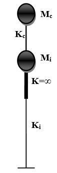
Figure 2. Model 2ddl [9]
h, R, kc, mc, mi, me and hc are the fluid height, radius tank, convective rigidity, convective mass, impulsive mass, total mass and convective height, as shown in Figure 2.
The rigidity of support can be calculated by using the finite element method or according to:
The rigidity of a frame support can be given by [4-6]:
$k_{i}=\frac{12 E_{c 1} I_{c 1} N_{c 1}}{h_{c 1}^{3}}$ $\left[ \frac{1}{\frac{2 I_{c 1} N_{p}\left(4 N_{p}^{2}-1\right)}{A_{c} R_{s}^{2}}+N_{p}+2\left(N_{p}-1\right) \frac{\frac{E_{c 1} I_{c 1}}{E_{c 1}}}{\frac{I_{b}}{L}}} \right]$ (7)
where, Ecl, hcl, Icl and Ncl are Young’s modulus of the column material, the height, the moment of inertia and the number of columns, respectively. Eb, L and Ib are Young’s modulus of the beam material, span and moment of inertia of the beam, respectively. Np is the number of panels and Rs is the staging radius.
By the method of Rayleigh, the rigidity of a tower with a constant section (Figure 3) is given by [31]:
$k_{i}=\frac{P}{P^{\prime}} \frac{3 E I}{l^{3}}$ (8)
$I=\pi R^{3} e$ (9)
$P^{\prime}=P+\frac{33}{140} p l$ (10)
Figure 3. Console (constant section)
where, $\mathrm{k}_{\mathrm{i}}, \mathrm{R}, \mathrm{E}, \mathrm{I}, \mathrm{l}, \mathrm{P}$ and $\mathrm{p}$ are rigidity of a tower, tower radius, Young’s modulus, the inertia of the cross section, the height of the tower, the weight of the concentrated mass and linear weight of the tower respectively.
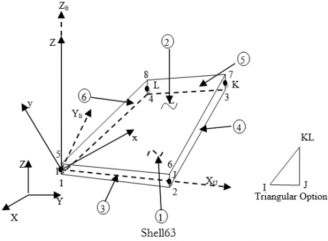
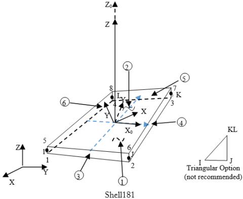
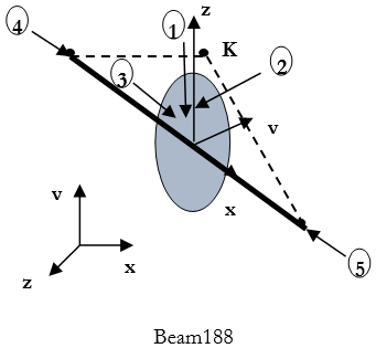
Figure 4. (a) Shell 63, (b) Shell 181, (c) Beam 188
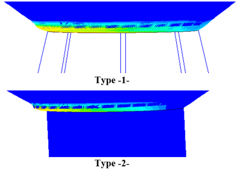
In this study, two elevated tanks with different supporting systems are modeled by Ansys software using the finite element technique. The wall and roof are modeled in this study by using Shell63 for modal analysis and shell181 “plastic capability’’ for transient analysis. The two elements have six degrees of freedom at each node: translations in the nodal x, y, and z directions and rotations about the nodal x, y, and z-axes. For the shaft support the beam188 with 2-node and six degrees of freedom at each node is used [32], as shown in Figure 4.
3.1 Fluid structure interaction
The effect of the fluid-structure interaction is taken into account by properly coupling the nodes that lies in the common faces of these two domains [33], as shown in Figure 5.
Figure 5. Fluid–structure models
3.2 Fluid domain
FLUID80 is used to model fluids contained within vessels having no net flow rate (Figure 6). This fluid element is particularly suitable for calculating hydrostatic pressures and fluid/solid interactions, acceleration effects, such as in sloshing problems. The element is defined by eight nodes having three degrees of freedom at each node: translation in the nodal x, y, and z directions. The stress-strain relationships used to develop the stiffness matrix and thermal load vector are as follows [32]:
$\left\{\begin{array}{l}\varepsilon_{B u l k} \\ \gamma_{x y} \\ \gamma_{y z} \\ \gamma_{x z} \\ R_{x} \\ R_{y} \\ R_{z}\end{array}\right\}=\left[\begin{array}{ccccccc}\frac{1}{K} & 0 & 0 & 0 & 0 & 0 & 0 \\ 0 & \frac{1}{S} & 0 & 0 & 0 & 0 & 0 \\ 0 & 0 & \frac{1}{S}& 0 & 0 & 0 & 0 \\ 0 & 0 & 0&\frac{1}{S} & 0 & 0& 0\\ 0 & 0 & 0 & 0 & \frac{1}{B} & 0 & 0 \\ 0 & 0 & 0 & 0 & 0&\frac{1}{B} &0 \\ 0 & 0 & 0 & 0 & 0 & 0&\frac{1}{B} \\\end{array}\right]=\left\{\begin{array}{l}P \\ x_{x y} \\ \tau_{y z} \\ \tau_{x z} \\ M_{x} \\ M_{y} \\ M_{z}\end{array}\right\}$
where,
$\varepsilon_{\mathrm{Bulk}}=\frac{\partial \mathrm{u}}{\partial \mathrm{x}}+\frac{\partial \mathrm{v}}{\partial \mathrm{y}}+\frac{\partial \mathrm{w}}{\partial \mathrm{z}}=$ Bulk strain
K = fluid elastic (bulk) modulus
P = pressure
γ = shear strain
S = K×10−9 (arbitrarily small number to give element some shear stability)
τ = shear stress
Ri = rotation about axis i
B=K×10−9 (arbitrarily small number to give element some rotational stability)
Mi=twisting force about axis i
A damping matrix is also developed based on:
$\left\{\begin{array}{c}\dot{\varepsilon_{\text {Bulk}}} \\ \dot{\gamma_{x y}} \\ \dot{\gamma_{y z}} \\ \dot{\gamma_{x z}} \\\dot{ R_{x}} \\ \dot{R}_{y} \\ \dot{R}_{z}\end{array}\right\}=\left[\begin{array}{ccccccc}0 & 0 & 0 & 0 & 0 & 0 & 0 \\ 0 & 1 / \eta & 0 & 0 & 0 & 0 & 0 \\ 0 & 0 & 1 / \eta & 0 & 0 & 0 & 0 \\ 0 & 0 & 0 & 1 / \eta & 0 & 0 & 0 \\ 0 & 0 & 0 & 0 & 1 / C & 0 & 0 \\ 0 & 0 & 0 & 0 & 0 & 1 / C & 0 \\ 0 & 0 & 0 & 0 & 0 & 0 & 1 / C\end{array}\right]=\left\{\begin{array}{c}P \\ \tau_{x y} \\ \tau_{y z} \\ \tau_{x z} \\ M_{x} \\ M_{y} \\ M_{z}\end{array}\right\}$
where, η= viscosity and C = 0.00001η.
Figure 6. Fluid 80
3.3 Free vibration analysis
Modal analysis is used to determine the vibration characteristics of this model. The important parameters in the design of a structure under dynamic loading conditions are the natural frequencies and mode shapes. The free system vibration equation is given by:
$[\mathrm{M}]\{\ddot{\mathrm{u}}\}+[\mathrm{K}]\{\mathrm{u}\}=0$ (11)
where, [M]=structural mass matrix, [K]=structural stiffness matrix, $\{\ddot{\mathrm{u}}\}$=nodal acceleration vector, and {u} nodal displacement vector. For a linear system, free vibration will be expressed as:
$\mathrm{u}=\phi_{\mathrm{i}} \mathrm{cosw}_{\mathrm{i}} \mathrm{t}$ (12)
where, $\phi_{i}$: eigenvector representing the mode shape of the ith natural frequency, wi: ith natural circular frequency in radians per unit time, t = time in seconds. Substitution of Eq. (12) in Eq. (11) gives [32]:
$\langle[K]-[M]\rangle \phi_{i}=0$ (13)
3.4 Transient analysis
For reasons of large displacements and relatively large deformations, the material and geometrical nonlinearities are considered. Plasticity was included using the software offers several options, among which we selected the simplest consisting of a bilinear kinematic hardening curve, taking into account the Beauschinger effect.
The transient dynamic analysis solves the basic equation:
of motion:
$[\mathrm{M}]\{\ddot{\mathrm{u}}\}+[\mathrm{C}]\{\dot{\mathrm{u}}\}+[\mathrm{K}]\{\mathrm{u}\}=\{\mathrm{F}(\mathrm{t})\}$ (14)
where, [C] = damping matrix, $\{\dot{\mathrm{u}}\}$=nodal velocity vector and {F(t)} = load vector [16].
3.5 Stability criteria
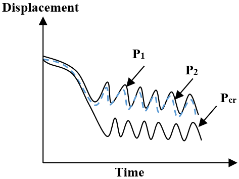
The most used stability criteria such as that of Budiansky-Ruth, the phase plane of energy is very time consuming (Figure 7-8). In this work, a prediction of the critical level is obtained by the Pseudo-Dynamic criterion. This prediction is then checked and improved using the conventional criteria [34-36].
(a) Criteria of Budiansky and Roth
(b) Criteria of Ari Gur and Simonetta
Figure 7. Critical load
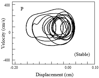
Figure 8. Phase plane diagram before and after the Pcr
In this section, free vibration analysis is carried out on the two elevated tanks to validate the proposed numerical model using the proposed FE technique (Figure 9). The values for the convective and impulsive responses were obtained and compared with the current practice values (which is based on the Housner’s formula). The results of modal analysis are summarized in Table 2 and 3, and Figures 10-11.
Figure 9. Elevated tank geometries
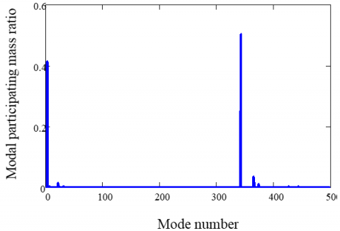
Figure 10. Mode participation mass ratio (Type 1)
Table 2. Frequency and effective mass fraction (Type 1)
|
Finite elements |
Eurocode 8 |
||||
|
Type |
Order |
Frequency |
Effective mass fraction |
Frequency |
|
|
|
1* |
0.156 |
0.41 |
0.155 |
|
|
Convective |
2 |
0.286 |
0.013 |
/ |
|
|
|
3 |
0.35 |
0.0035 |
/ |
|
|
|
1* |
0.77 |
0.51 |
0.95 |
|
|
Impulsive |
2 |
6.01 |
0.035 |
/ |
|
|
|
3 |
16.57 |
0.011 |
/ |
|
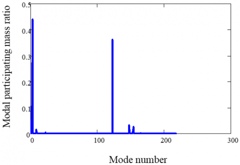
Figure 11. Mode participation mass ratio (Type 2)
Table 3. Frequency and effective mass fraction (Type 2)
|
Finite elements |
Eurocode 8 |
||||
|
Type |
Order |
Frequency |
Effective mass fraction |
Frequency |
|
|
|
1* |
0.156 |
0.54 |
0.157 |
|
|
Convective |
2 |
0.29 |
0.016 |
/ |
|
|
|
3 |
0.35 |
0.00013 |
/ |
|
|
|
1* |
2.87 |
0.37 |
3.5 |
|
|
Impulsive |
2 |
9.99 |
0.033 |
/ |
|
|
|
3 |
15.37 |
0.027 |
/ |
|
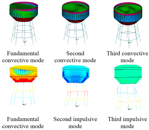
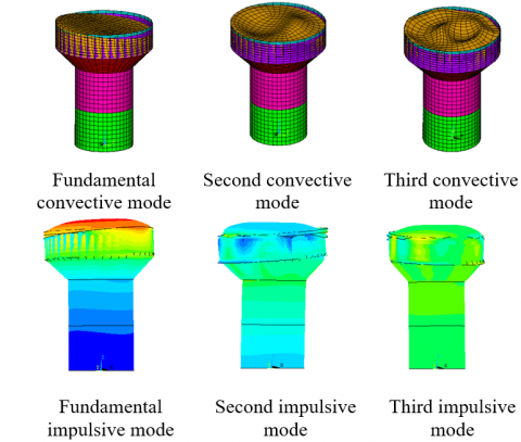
The obtained mode shows that the shapes of fundamental mode involve sloshing of the contained liquid without any participation of the shell walls (given by Veletsos) [27], as shown in Figures 12-13. The fundamental impulsive mode is a column mode type. It can be observed that the calculated FE results are in reasonable agreement with current practice values. The two fundamentals (impulsive and convective) modes can achieve modal mass participation for more than 90% of the total mass of the system which means that the two modes are the most dominant. The tank undergoes one of the large deformations. This is due to higher stiffness of the support in comparison with the tank part [9]. These results indicate the validity of the proposed FE model.
Figure 12. Modal shape (Type 1)
Figure 13. Modal shape (Type2)
From Tables 2 and 3, we can realize that the convective period remains the same for the two types of the supporting systems, which means that the convective component is independent of the support type. On the contrary, a significant difference is observed between the impulsive periods of the two types of elevated tanks.
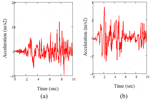
The Budiansky and Roth criterion, which was used in the literature to determine the dynamic buckling load, is employed in this study. Different analyses of the two elevated tanks for rising PGA (peek ground acceleration) levels are done, and the two types of support are subjected to the horizontal excitations of the San Fernando 1971 and El Centro1940 earthquakes (Figure 14).
Figure 14. Accelerograms (a) San Fernando, PGA =12.02 m/ s², (b) El centro PGA =3.41 m/ s² San Fernando 1971 earthquakes
5.1 San Fernando earthquake
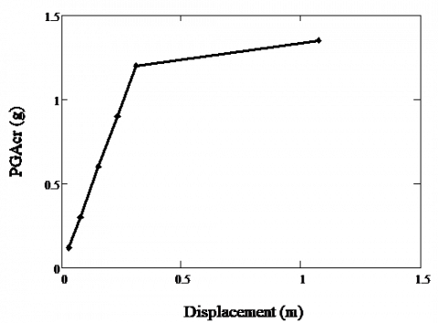
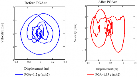
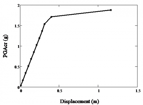
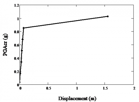
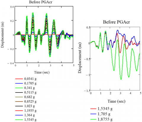
Shows the pseudo equilibrium path for the two type of elevated tanks. The discontinuity on curve indicates that the (PGAcr) occurs at 1.5 for type 2 and 1.2 g for type 1. It shows several history curves corresponding to different levels of excitation. Figures 15-16 show clearly the difficulty of using the Budiansky-Ruth criterion for determining the (PGA)cr which requires, in fact, a lot of experience and attention. At level 1.2 and 1.5, a disproportionate increase in displacements is distinguished.
Figure 15. Pseudo-Equilibrium path for elevated tank type-2-
Figure 16. Pseudo-equilibrium path for elevated tank type-1-
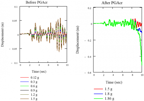
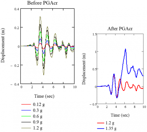
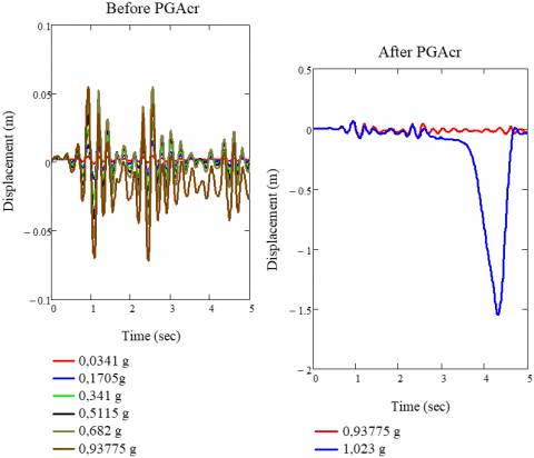
Figures 17-18, show several history curves corresponding to different levels of excitation. These Figures show clearly the difficulty of using the Budiansky-Ruth criterion for determining the (PGA)cr which requires, in fact, a lot of experience and attention.
Figure 17. Time history curves before and after PGAcr for elevated tank type-2-
Figure 18. Time history curves before PGAcr for elevated tank type-1-
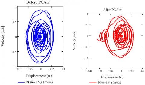
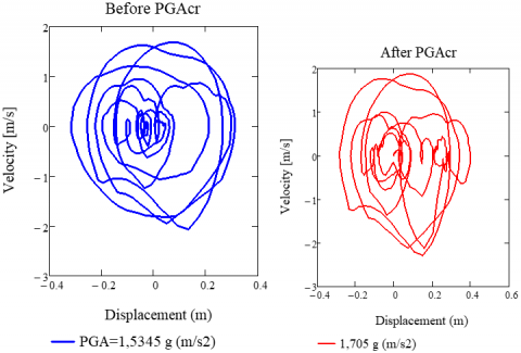
This increase does not correspond to a monotonic jump for the above-mentioned reasons. The phase planes criterion illustrated in Figures 19 and 20 shows more easily in this case the instability in the vicinity of the (PGA). The difficulty for using this criterion is, in some cases, the same as that reported for Budiansky and Ruth, but the use of the two criteria simultaneously can be more illustrative.
Figure 19. Phase plane before and after PGAcr for elevated tank type-2-
Figure 20. Phase plane before and after PGAcr for elevated tank type-1-
Figure 21. Dynamic buckling of elevated tanks under San Fernando earthquake
5.2 El Centro earthquake
Figures 22-27 give the PGAcr for this excitation. Using an estimation given by the pseudo dynamic path, the Budiansky–Ruth and phase plane criteria are then used to confirm the obtained value.
Figure 22. Pseudo-equilibrium path for the elevated tank. Type -1-
Figure 23. Pseudo-equilibrium path for the elevated tankType -2-
Using an estimation given by the pseudo dynamic path, the Budiansky–Ruth and phase plane criteria are then used to confirm the obtained value
Figure 24. Time history curves before PGAcr for elevated tank type-1-
Figure 25. Time history curves before PGAcr for elevated tank type-2-
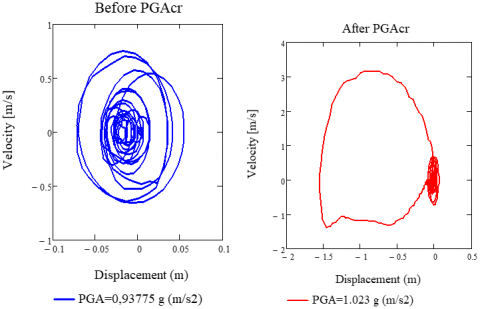
Figure 26. Phase plane before PGAcr for elevated tank type-1-
Figure 27. Phase plane before PGAcr for elevated tank type-2-
5.3 Discussion of the results
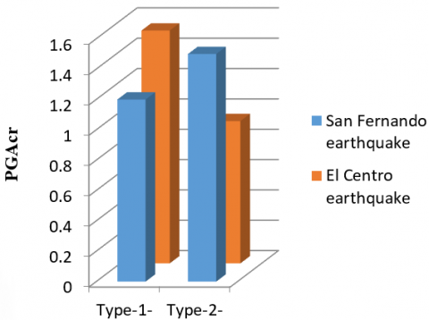
The comparison between the pseudo dynamic path curves for the two elevated tanks clearly shows the big difference between the displacements that corresponds to each PGA for the two elevated tanks. Comparing the PGAcrt obtained for two models, it can be seen that the PGAcr of the elevated tank with tower support is 1.5 g m / s2 and 1.2g m / s2 for a raised tank with frame support; with 20% difference for San Fernando earthquake. 1.5345 g m / s2 for elevated tank with a frame support and 0.93775 g m / s2 for elevated tank with a tower support; and 38.88% difference for El Centro earthquake.
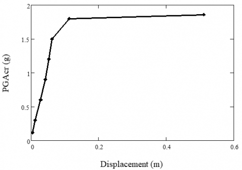
The curve of the type 1 model indicates that the critical value PGA (PGAcr) occurs at 1.5345 g (El Centro excitation), and it is increased by 21.79% compared to the San Fernando earthquake result (Figure 28).
In the curve of the type 2- model, the PGAcr occurs at level 0.93775 g (El Centro excitation), and it is decreases by 37.48% compared to the San Fernando earthquake result (Figure 28).
From Figure 21, it is concluded that the maximum stresses are located along the support-tank interface, and this is due to the change of rigidity and geometry at this interface.
Figure 28. Comparison between the values of PGAcr
In high seismicity areas and high population density, a tank rupture following an earthquake can cause enormous damage and loss of property and human life. In addition, the use of tanks in the nuclear industry and the storage of chemical or toxic materials make this type of structure very sensitive to their safety with regard to seismic effect. In the present work, an efficient 3D finite element method analysis was used to analysis the dynamic behavior of two elevated tanks, considering nonlinear temporal analysis, wall flexibility, the material and geometric non-linearities, and fluid-structure interactions, using ANSYS software. First, a modal analysis was carried out and compared with the Eurocode Code 8 to confirm the numerical models, and to view the effect of the support system on the frequencies of the two structures. Secondly, the dynamic buckling analysis of the two elevated tanks was performed to review also the effect of the support system on the dynamic behavior of these two elevated tanks, the obtained results showed that:
The frequency of the convective component is independent of the rigidity of the structure, and the frequency of the impulsive component depends on the rigidity of the structure which confirms Housner’s theory. The impulsive mode frequency of elevated tank with tower support is higher than the raised tank with frame type which means that tower type is more rigid than frame type. The two fundamental modes (impulsive and convective) reach modal mass participation of more than 90% of the total mass of the system, which means that the two fundamental modes are dominant.
The transient study of the elevated tanks under the earthquakes of San Fernando1971 and El Centro 1940 shows that:
Comparing the PGAcrt obtained for two models, it can be seen that the type of support has a great influence on the dynamic behavior of the elevated tanks.
The PGAcr of the structure does not only depend on the characteristics of the structure, but also the frequency content and characteristics of the earthquake.
Most of the deformations in the support tank interface resulted from the sudden change of rigidity and geometry of the interface (higher stiffness in the support of the tank).
The criterion of dynamic buckling response is studied through testing the deformations of the excitation critical level. The results of the deformations of tanks indicated a high level of explosiveness in plastic buckling type.
Finally, based on the comparison made between two elevated tanks results, it can be concluded that the highest value of PGAcr does not always occur in the more rigid supporting system, and PGAcr does depend on characteristics of the earthquake excitation These results indicate the need for consideration of the support rigidity and frequency content of earthquake excitation design in current practice.
This work was supported by FIMAS Laboratory, University of Tahri Mohammed Bechar, Algeria.
[1] Hadj-Djelloul, N.D., Djermane, M. (2020). Effect of geometric imperfection on the dynamic of elevated water tanks. Civil Engineering Journal, 6(1): 85-97. https://doi.org/10.28991/cej-2020-03091455
[2] Housner, G.W. (1963). The dynamic behavior of water tanks. Bulletin of the seismological society of America, 53(2): 381-387.
[3] Joshi, S. (2000). Equivalent mechanical model for horizontal vibration of rigid Intze tanks. ISET Journal of Earthquake Technology, 37(1-3): 39-47.
[4] Dutta, S.C., Jain, S.K., Murty, C.V.R. (2000). Assessing the seismic torsional vulnerability of elevated tanks with RC frame-type staging. Soil Dynamics and Earthquake Engineering, 19(3): 183-197. https://doi.org/10.1016/S0267-7261(00)00003-8
[5] Dutta, S.C., Jain, S.K., Murty, C.V.R. (2000). Alternate tank staging configurations with reduced torsional vulnerability. Soil Dynamics and Earthquake Engineering, 19(3): 199-215. https://doi.org/10.1016/S0267-7261(00)00004-X
[6] Dutta, S.C., Jain, S.K., Murty, C.V.R. (2001). Inelastic seismic torsional behavior of elevated tanks. Journal of Sound and Vibration, 242(1): 151-167. https://doi.org/10.1006/jsvi.2000.3343
[7] Shrimali, M.K., Jangid, R.S. (2003). Earthquake response of isolated elevated liquid storage steel tanks. Journal of Constructional Steel Research, 59(10): 1267-1288. https://doi.org/10.1016/S0143-974X(03)00066-X
[8] Livaoğlu, R., Doğangün, A. (2006). Simplified seismic analysis procedures for elevated tanks considering fluid–structure–soil interaction. Journal of Fluids and Structures, 22(3): 421-439. https://doi.org/10.1016/j.jfluidstructs.2005.12.004
[9] Moslemi, M., Ghaemmaghami, A.R., Kianoush, M.R. (2016). Parametric based study for design of liquid-filled elevated tanks. Canadian Journal of Civil Engineering, 43(7): 619-630. https://doi.org/10.1139/cjce-2015-0218
[10] Allen, L.R., Hutchinson, G.L., Stevens, L.K. (1990). Buckling considerations in the design of elevated steel water tanks. Thin-Walled Structures, 9(1-4): 389-406. https://doi.org/10.1016/0263-8231(90)90054-3
[11] Malhotra, P.K., Wenk, T., Wieland, M. (2000). Simple procedure for seismic analysis of liquid-storage tanks. Structural Engineering International, 10(3): 197-201. https://doi.org/10.2749/101686600780481509
[12] Algreane, G.A., Osman, S.A., Karim, O.K., Kasa, A. (2011). Behavior of elevated concrete water tank subjected to artificial ground motion. EJGE, 16: 387-406.
[13] Omidinasab, F., Shakib, H. (2012). Seismic response evaluation of the RC elevated water tank with fluid-structure interaction and earthquake ensemble. KSCE J Civ Eng, 16: 366-376. https://doi.org/10.1007/s12205-011-1104-1
[14] Sweedan, A.M.I. (2009). Equivalent mechanical model for seismic forces in combined tanks subjected to vertical earthquake excitation. Journal of Thin Walled Structures, 47: 942-952. https://doi.org/10.1016/j.tws.2009.02.001
[15] Chaduvula, U., Patel, D., Gopalakrishnan, N. (2013). Fluid-structure-soil interaction effects on seismic behaviour of elevated water tanks. Procedia Engineering, 51: 84-91. https://doi.org/10.1016/j.proeng.2013.01.014
[16] Jabar, A.M., Patel, H.S. (2012). Seismic Behavior of RC Elevated Water Tank under different staging pattern and earthquake characteristics. International Journal of Advanced Engineering Research and Studies, IJAERS, 1.
[17] Mor Vyankatesh, K., More Varsha, T. (2017). Comparative Study on Dynamic Analysis of Elevated Water Tank Frame Staging and Concrete Shaft Supported. IOSR Journal of Mechanical and Civil Engineering (IOSR-JMCE), 14(1): 38-46. https://doi.org/10.9790/1684-1401013846
[18] Pole, S.M., Khedikar, A. (2017). Seismic behaviour of elevated water tank under different staging pattern. International Journal of Engineering and Management Research (IJEMR), 7(3): 199-205.
[19] Liu, W.K., Lam, D. (1983). Nonlinear analysis of liquid-filled tank. Journal of Engineering Mechanics, 109(6): 1344-1357. https://doi.org/10.1061/(ASCE)0733-9399(1983)109:6(1344)
[20] Nagashima, H., Kokubo, K., Takayanagi, M., Saitoh, K., Imaoka, T. (1987). Experimental study on the dynamic buckling of cylindrical tanks: Comparison between static buckling and dynamic buckling: Solid-mechanics, strength of materials. JSME International Journal, 30(263): 737-746. https://doi.org/10.1299/jsme1987.30.737
[21] Virella, J.C., Godoy, L.A., Suárez, L.E. (2006). Dynamic buckling of anchored steel tanks subjected to horizontal earthquake excitation. Journal of Constructional Steel Research, 62(6): 521-531. https://doi.org/10.1016/j.jcsr.2005.10.001
[22] Djermane, M., Zaoui, D., Labbaci, B., Hammadi, F. (2014). Dynamic buckling of steel tanks under seismic excitation: Numerical evaluation of code provisions. Engineering Structures, 70: 181-196. https://doi.org/10.1016/j.engstruct.2014.03.037
[23] Soroushnia, S., Tafreshi, S.T., Omidinasab, F., Beheshtian, N., Soroushnia, S. (2011). Seismic performance of RC elevated water tanks with frame staging and exhibition damage pattern. Procedia Engineering, 14: 3076-3087. https://doi.org/10.1016/j.proeng.2011.07.387
[24] Steinbrugge, K.V. (1970). Earthquake damage and structural performance in the United States. pp. 183-226.
[25] European Committee for Standardization (CEN). (2006). Eurocode 8: Design of structures for earthquake resistance—Part 4: Silos, tanks and pipelines.
[26] Veletsos, A.S., Yang, J.Y. (1977). Earthquake response of liquid storage thanks. Proc. 2nd Adv. Civil. Eng. through Eng. Mech. Conf., ASCE, North Carolina, pp. 1-24.
[27] Veletsos, A. S. (1984). Seismic response and design of liquid storage tanks. Guidelines for the Seismic Design of Oil and Gas Pipeline Systems, pp. 255-370.
[28] Haroun, M.A., Housner, G.W. (1981). Earthquake response of deformable liquid storage tanks. Journal of Applied Mechanics, 48: 411-418. https://doi.org/10.1115/1.3157631
[29] ACI Committee 350. (2006). Seismic Design of Liquid-containing Concrete Structures and Commentary (ACI 350.3-06): An ACI Standard. American Concrete Institute.
[30] American Water Works Association (AWWA), 1984 and 2005, Welded steel tanks for water storage. AWWA D100, CO.
[31] Capra, A., Davidovici, V. (1980). Calcul dynamique des structures en zone sismique (No. BOOK). Eyrolles.
[32] The ANSYS Structural Software System. ANSYS INC, Vol. 12.
[33] Cheng, X., Jing, W., Yin, C., Li, C. (2018). Stability parameter analysis of a composite foundation of an oil storage tank in a loess area treated with compaction piles. Soils and Foundations, 58(2): 306-318. https://doi.org/10.1016/j.sandf.2018.02.004
[34] Budiansky, B. (1962). Axisymmetric dynamic buckling of clamped shallow spherical shells. NASA TN, 1510: 597-606.
[35] Djermane, M., Chelghoum, A. (2007). Nonlinear dynamic and dynamic buckling of thin shells using a drilling finite element. International Journal of Advanced Manufacturing Technology, 1(2): 175-84.
[36] Ari-Gur, J., Simonetta, S.R. (1997). Dynamic pulse buckling of rectangular composite plates. Composites Part B: Engineering, 28(3): 301-308. https://doi.org/10.1016/S1359-8368(96)00028-5