Ihsan Z. Salim*![]() | Najim A. Jassim
| Najim A. Jassim![]()
© 2024 The authors. This article is published by IIETA and is licensed under the CC BY 4.0 license (http://creativecommons.org/licenses/by/4.0/).
OPEN ACCESS
This study examines the influence of hot air flow trajectories within steam generators on their thermal efficiency. Specifically, the investigation focuses on the augmentation of the convection heat transfer coefficient, achieved through enhanced contact efficiency between hot air and water pipes, thereby increasing convective heat. Computational Fluid Dynamics (CFD) served as a preliminary tool for evaluating the thermal dynamics of the steam generator, encompassing the movement of flame and hot air as well as steam generation within the pipes. The introduction of partitions was found to refine the convective heat transfer coefficient in the steam generator, particularly in the inner and outer coils. However, a decrease in the heat transfer coefficient was noted around the vertical cylinder, compared to the configuration without partitions. The inclusion of a single separator in the evaporator generator led to a 29% increase in the total convective heat transfer coefficient, while the utilization of two separators resulted in a 23% increase. These findings highlight the significance of structural modifications in steam generators, specifically through the strategic placement of separators and partitions, in elevating thermal efficiency.
convection heat-transfer coefficient, steam generator, two phase flow
A steam generator is a container in which steam is generated from water by the heat generated from burning fuel. A steam generator is used in many engineering applications (power plant and building heating, in addition to multiple uses in the chemical and oil industries).
The evaluation of steam generator performance depends on the maximum heat absorbed and the minimum heat loss. In this case, using a water tube steam generator is preferable, as this type has a higher steam generation rate in addition to being smaller and less expensive [1].
The design of various thermal equipment, especially combustion equipment in recent times, depends mainly on the simulation of flow and heat transfer using CFD as an initial stage to evaluate the thermal performance of the equipment in addition to fluid flow (flame movement and hot air as well as steam generation inside the pipes), where CFD models are fundamental values for steam generator designers, to study the efficiency in generating steam [2].
The proposed design of the steam generator consists of a vertical cylinder connected to a two-layer spiral coil. Due to the special geometric structure of the spirally coiled tube, the stages of phase change from liquid to vapor in the tube are affected not only by gravitational and shear forces but also by centrifugal force and secondary flow, while we do not notice the presence of centrifugal force when boiling processes occur inside the vertical tube. Steam diverts in and up the cross-section, so drying first takes place locally in the inner part and upper part of the cross-section of a spirally wound tube. As the secondary fluid is heated even more, the drying zone along the spirally coiled tube slowly grows to cover the whole cross-section, causing the complete change from water to vapor [3]. Because centrifugal force creates a secondary flow inside a helically coiled tube, the boiling process inside is more complex than in a straight tube [4].
Mahvelati et al. [5] presented a study on the coupled combustion inside the furnace and the steam generation inside the radiant and convection tubes through a typical Once-Through Steam Generator (OTSG). A 3D CFD model coupling the combustion and the two-phase flow was developed to model the entire system of OTSG. The results represented the shape of the jet and showed that the flow gas goes through the transition part, passes over the convective tubes, and then reaches the entrance of the stack. The temperature profiles indicated that the flow gas passing the transition zone and entering the convective section has a considerably high temperature (1152.8℃), which is the consequence of combustion and heat production in the radiant section [5].
Riyandwita et al. [6] presented a study on the analytical design of a helical coal steam generator for a hot-temperature gas reactor. A compact design of a once-through counter-flow helical coil steam generator is proposed. A simple thermodynamic analysis combined with an empirical heat transfer coefficient for the convective and boiling processes inside the steam generator at constant pressure was performed. It is shown that with an inlet water temperature of 418.15K and a helium gas inlet temperature of 973.15K at 4.27 kg/s and 34.2 bar, the heating fluid produced an output helium gas temperature of 511.42K.
da Silva et al. [7] applied exergy analysis to evaluate boilers, which are responsible for considerable exergy destruction in traditional, rankine-based power plants. The study case considered a coal-fueled water tube boiler. The reference steam generator defined herein to develop the different equations is just a way in which the relevance of the science is demonstrated. From an energy assessment viewpoint, the major potential for improvement identified was the use of exhaust gases (68%). Exergy assessment indicated that more exergy was destroyed due to combustion and heat transfer within the boiler (82%), while exhaust gases represented only 11% of destroyed exergy.
Kang and Rong [8] also suggest simplified models based on numerical simulations and analytical methods for radiation calculation, convection, and conduction heat transfer in heat treatment processes. View factors between the furnace and workpieces, especially among workpieces, are estimated by evaluating exposed surface areas and integrating the heat transfer models with the furnace model to simulate the heat treatment processes of workpieces in the furnace and then to improve heat treatment quality and efficiency by optimizing workpiece loading and the thermal schedule. Drosatos's work an in-house-built code was incorporated into the CFD model for the simulation of the boiler's convection section. The investigation followed a parametric approach, assuming three different ash contamination thickness distributions. The three distributions were appropriately chosen to fit the CFD results of the internally designed model at full load with the results of the CFD using the total heat exchanger model provided by ANSYS Fluent® as well as the results of the ASPEN Plus® process model plus experimental data before retrofitting procedures. Based on the results, it can be concluded that the internally designed model is robust, consistent, and validated [9].
Wu et al. [10] provided dynamic simulations of a movable trinomial volute, a one-time steam generator, and a controller design. This model includes three zones moving along the boundary of the OTSG spiral. The OTSG is divided into a sub-cooled region, a two-phase region, and a superheated region, with moving boiling boundaries between each region. Results show good agreements among the nonlinear model, the linear model, and the RELAP5 model, with acceptable errors. This model can be applied to dynamic simulations and the controller design of a helical coil OTSG with a constant primary-side flow rate.
The path taken by the hot air flow inside the steam generator affects the heat transfer properties between the hot air and the water pipes inside the steam generator. During this study, we examined the effect of controlling the hot air path on the thermal efficiency of the steam generator by increasing the convection heat transfer coefficient due to increasing the contact efficiency between the hot air and the pipes and thus increasing the convective heat, as well as increasing the heat efficiency due to reducing the temperature of the exhaust air exiting the steam generator.
This present work aims to reduce the heat lost with the exhaust gas flow rate by controlling the flow of hot air inside the oven and producing exhaust gases with temperatures as low as possible by studying the effect of adding partition between the helical coil tubes on the hot air path and thus changing the values of the heat transfer coefficient by convection, which in turn works to improve the heat transfer between the hot air in the steam generator and the water inside the tubes.
2.1 General calculation
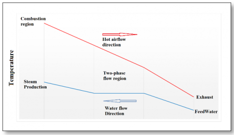
The steam generator depends on the principle of its work on the conversion of thermal energy from the chemical energy resulting from the combustion of the fuel-air mixture, where this heat is transferred to the cold water entering the steam generator to converted into hot water as a first stage of flow. Then the water flow form moves to a two-phase (Liquid-Vapor) before the water turns into steam. The heating continues after that in the superheat phase. Conversely, the air temperature inside the Furnace gradually decreases in conjunction with the stages of changing the water phase from liquid to vapour, as shown in Figure 1. Notable features of the heat transfer process within a steam generator include.
Figure 1. Heat exchanger depiction
Table 1 shows all the main parameters used in the design of the steam generator in this research paper.
Table 1. A typical steam generator's main parameter
|
Parameter |
Value |
|
Inlet water flow rate (kg/hr.) |
30 |
|
Inlet water Temperature (℃) |
80 |
|
Inlet water Pressure (bar) |
8 |
|
Outlet Steam Temperature (℃) |
180-300 |
2.1.1 Water and steam circuit
To design a steam generator, first know the thermal energy transferred from hot gases to water and steam inside the tubes by knowing the incoming and outgoing temperatures of both water and hot gases, knowing that the transferred thermal energy is related to both the heat transfer coefficient and the surface area of the heat exchanger, as well as the difference in degrees the heat.
The heat needed to generate steam is divided into three phases inside the steam generator shown in Figure 1, which is the heat needed to raise the water temperature to the boiling point, the heat needed to turn water into steam (latent heat) and the heat needed to raise the steam temperature to a degree Design steam temperature, so the total amount of heat is:
$Q_{\text {total }}=m_{\text {water }}\left(h_{\text {Water inlet }}-h_{\text {Steam outlet }}\right)$ (1)
$Q_{\text {total }}=Q_{\text {Liq. }}+Q_{\text {Lat. }}+Q_{\text {Vap. }}$ (2)
where:
$Q_{\text {Liq. }}=m_{\text {water }} C_{\text {water }}\left(T_{\text {Water }}-T_{\text {sat. }}\right)$ (3)
$Q_{\text {Lat. }}=m_{\text {water }}($L.H.) (4)
Hence (L.H.) is specific latent heat of a substance:
$Q_{\text {Vap. }}=m_{\text {Vap. }} C_{p . \text { Vap. }}\left(T_{\text {Sat. }}-T_{\text {Exit }}\right)$ (5)
But the total heat required to convert water into steam all comes from the external heat applied to the walls of the tubes:
$Q_{\text {total }}=Q_{\text {flux }}$ (6)
2.1.2 Furnace
Convective heat resistance between the primary fluid and the outer tube wall, heat conduction resistance of the tube wall, convective heat resistance between the hot air and the inner tube wall, and fouling thermal resistance brought on by impurities deposited on the inner tube wall are the four thermal resistances that occur during the heat transfer process [11]. The thermal efficiency of the steam generator, according to thermodynamics, is the amount of thermal energy expected to be produced from burning fuel minus the total dissipated energies, which are divided into [7]:
1. Energy losses due to incomplete combustion (Q1)
2. Energy losses in exhaust gases (Q2)
3. Surface heat losses (Q3)
4. Energy losses in ashes (Q4)
5. Energy losses due to blowdowns (Q5)
$\eta_{\text {furn }}=1-\frac{\left(Q_1+Q_5+Q_3+Q_4+Q_5\right)_{\text {Loss }}}{\dot{m}_{\text {fuel }}(L H V)}$ (7)
In other words, the energy produced by fuel combustion is divided into two main parts. The first is the heat energy applied to the pipes (the energy used), and the second part includes the wasted energy, so:
$\dot{m}_{\text {fuel }}(L H V)=Q_{\text {flux }}+\left(Q_1+Q_5+Q_3+Q_4+Q_5\right)_{\text {Loss }}$ (8)
2.1.3 Fuel-burning system
The energy generated by the gas ignition process inside the steam generator, as well as the characteristics of the air involved in the representation of the liquid flow inside the steam generator (including temperature, viscosity, density, etc.), is essential to comprehend the series of chemical reactions of gas ignition.
In the full burning of propane equation, which accounts for 70% of LPG, enough oxygen is required for propane to burn completely, producing water vapour, carbon dioxide, and approximately (49 MJ/kg) of heat in the process. Thus, the whole propane combustion equation in both language and chemical formulae is as follows:
Propane + Oxygen → Carbon Dioxide + Water + Heat (49 MJ/kg)
$\begin{aligned} \mathrm{C}_{3.5} \mathrm{H}_9+5.75 \mathrm{O}_2 & +(5.75 * 3.8) \mathrm{N}_2 \rightarrow 3.5 \mathrm{CO}_2 \\ & +4.5 \mathrm{H}_2 \mathrm{O}+22 \mathrm{~N}_2 \\ & +(49 \mathrm{MJ} / \mathrm{kg})\end{aligned}$ (9)
The combustion of 1 kilogram of LPG requires about 15.6 kilograms of air (that is, given the composition of the air, about 12 kilograms of nitrogen and 3.6 kilograms of oxygen); the reaction produces about 12 kilograms of nitrogen (this gas being chemically neutral, it did not participate in the combustion), 3 kilograms of carbon dioxide (CO2) and 1.6 kilograms of water (H2O) and the temperature reaches (2000℃).
Notes:
2.2 Mathematical calculation
The first stage of this research is to calculate the dimensions of the steam generator using the three heat transfer equations (heat transfer by conduction, heat transfer by convection, and heat transfer by radiation) by entering the engagement data, including the specifications and quantities of water entering the steam generator, as well as the specifications of the steam produced, in addition to some hypotheses. To facilitate calculations where steam generator efficiency and hot air specifications are imposed.
2.2.1 Conduction calculation
Fundamental equations for steady heat conduction through cylindrical geometry where the heat transfer is normal to the axis, as in heat flow through a cylindrical vessel or pipe wall:
$Q_{\text {cond. }}=\frac{2 . \pi . L . k . \Delta T}{\ln \left(D_o / D_i\right)}$ (10)
2.2.2 Convection calculation
Heat transfer occurs between a solid and a moving fluid next to it due to the movement of the molecules of the fluid itself. This is after replacing the hot particles close to the surface of the solid with the cold particles that come in their place. Heat transfer of this type occurs in the thin film or layer adjacent to the solid surface. Newton's law of cooling applies to convective heat transfer.
$Q_{\text {conv. }}=h . A . \Delta T$ (11)
Numerous empirical correlations of the heat transfer coefficient of flows through cylinders have been developed experimentally by several researchers [12]. The average Nusselt number for flow across cylinders can be expressed compactly as:
$N u=\frac{h \cdot D}{k}=C \cdot \operatorname{Re}^m \cdot \operatorname{Pr}^n$ (12)
The flow parallel to the length of the vertical tube is treated as a flat plate exposed to a uniform heat flow, and thus the average Nusselt number over the entire length of the tube is determined in Table 2.
For the forced load on the cross-section of the cylinder (n=1/3) and the following table of experimentally determined constants C and m depending on the Reynolds number because the cases studied in this report include different Reynolds numbers depending on the Variety and the location of the tube [12].
Table 2. Empirical correlations for the average Nusselt number for forced convection
|
Type of Flow |
Range of Re |
C |
m |
n |
Nu |
|
|
The flow parallel to the vertical cylinder |
Laminar |
0.664 |
0.5 |
1/3 |
$(0.664) \operatorname{Re}^{0.5} \cdot \operatorname{Pr}^{1 / 3}$ |
|
|
Flow cross coil tube |
Inner coil |
40-4000 |
0.683 |
0.466 |
1/3 |
$(0.683) R e^{0.466} \cdot \operatorname{Pr}^{1 / 3}$ |
|
Outer coil |
||||||
The total amount of heat transferred by convection is equal to the sum of heat transferred by convection in each area, so:
$\begin{gathered}Q_{\text {conv. }}=\left[\left(h_1 \cdot A_1\right) \cdot \Delta T_1+\left(h_2 \cdot A_2\right) \cdot \Delta T_2+\cdots\right. \left.+\left(h_n \cdot A_n\right) \cdot \Delta T_n\right]\end{gathered}$ (13)
2.2.3 Radiation calculation
Heat transfer by radiation takes place between two opposite surfaces, but in the furnace, the process takes place between the hot gas and the outer surface of the water pipes, so calculating the heat transferred by radiation, in this case, requires equations that include a specific shape coefficient.
Furnace heat transfer calculation involves the radiative heat transfer from the flame or high-temperature combustion products around the furnace wall. Assume that the furnace surface equals the effective radiative heating surface of the same side of the furnace wall. The radiative heat transfer of the flame is transferred to the water wall through the plane parallel to a water wall panel; this plane can be considered the flame’s radiative plane, the temperature of which is equal to the average flame temperature. The emissivity equals the radiative emissivity from the flame to the furnace surface. According to the heat transfer principle, radiative heat transfer between the flame and furnace surface can be expressed as follows [13]:
$Q_{\text {rad. }}=\frac{\sigma A_r\left(T_g^4-T_w^4\right)}{\frac{1}{\varepsilon_g}+\frac{1}{\varepsilon_w}-1}$ (14)
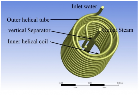
The previous literature was relied upon in the design of the current steam generator with the integration of the steam separation cylinder with the conical tubes in the steam generator, where the isolation cylinder was placed in the core of the fireside as shown in Figure 2 and Figure 3, which represents the integrated design of the steam model.
Figure 2. Steam generator
Through preliminary calculations that resulted in the necessary pipe length, in addition to choosing suitable diameters with those who work with it in such a case, and to improve the thermal performance of the steam generator, a partition was added consisting of a cylindrical container turned upside down (open from the bottom) between the inner helical tube and the tube The outer conical partition, as well as adding another cylindrical wall open from the top between the vapour isolation cylinder in the core of the fireside and the inner helical tube. The purpose of adding these partitions is to increase the length of the path that the hot air takes inside the steam generator before leaving the chimney. Thus, these partitions increase the speed of the air passing around the helical tubes, which in turn works to transfer the enormous amount of heat from the hot air to the water tubes, and this is what the results obtained in this study will show. Table 3 shows all the dimensions of the steam generator along with the dimensions of the internal pipes used, while the other table shows the data used in the design calculations of the steam generator.
Figure 3. Steam generator (Water-Vapor side)
Table 3. Steam generator dimensions
|
Item |
Dimension (mm) |
|
The diameter outer wall of the steam generator $\left(D_{S G}\right)$ |
360 |
|
The height outer wall of the steam generator $\left(H_{S G}\right)$ |
600 |
|
The vertical Separator diameter $\left(D_{VS}\right)$ |
30 |
|
The vertical Separator height $\left(H_{VS}\right)$ |
400 |
|
Inner helical tube diameter $\left(D_{IC}\right)$ |
16 |
|
Inner helical tube length $\left(L_{IT}\right)$ |
7,540 |
|
Inner helical tube coil diameter $\left(D_{IC}\right)$ |
240 |
|
Number of tubes in Inner coil |
11 |
|
Outer helical tube diameter $\left(D_{OT}\right)$ |
16 |
|
Outer helical tube length $\left(L_{OT}\right)$ |
11,060 |
|
Outer helical tube coil diameter $\left(D_{OC}\right)$ |
320 |
|
Number of tubes in Outer coil |
11 |
|
First partition diameter $\left(D_{FP}\right)$ |
200 |
|
First partition tube height $\left(H_{FP}\right)$ |
450 |
|
Second partition diameter $\left(D_{S P}\right)$ |
280 |
|
Second partition height (Li) $\left(H_{S P}\right)$ |
450 |
|
Inlet hot air diameter $\left(D_{AI}\right)$ |
50 |
|
Outer hot air diameter $\left(D_{AO}\right)$ |
50 |
2.3 CFD modeling
2.3.1 Fireside CFD modeling
Using the CFD ANSYS Fluent software, solve the combustion model for the Reynolds Averaged Navier Stokes (RANS) equation with an achievable perturbation model [4].
Continuity equation:
$\frac{\partial \rho}{\partial t}+\nabla \cdot(\rho U)=0$ (15)
The Navier-Stokes equation for viscous compressible fluid with constant viscosity:
$\rho \frac{\partial U}{\partial t}+U . \nabla U=\rho X-\nabla p+\mu \nabla^2 U+\frac{\mu}{3} \nabla(\nabla . U)$ (16)
Hence: (U) is velocity vector and (X) is body force per unit mass.
An achievable (k$-\varepsilon$) turbulence model was used for the current simulations for the flow inside the furnace to be completely turbulent. This is an appropriate empirical model for predicting flows involving shear stress which is based on the transfer equations for turbulence kinetic energy(k) and dissipation rate ($\varepsilon$) at large turbulent Reynolds number.
Energy equation for viscous compressible fluid:
$\rho \frac{\partial Q}{\partial t}+\phi=\rho \frac{\partial h}{\partial t}-\frac{\partial p}{\partial t}$ (17)
Hence:
$\boldsymbol{h}=E+\frac{p}{\rho}=C_p T$ (18)
$\rho \frac{\partial Q}{\partial t}=\nabla \cdot(k \nabla T)$ (19)
$\nabla \cdot(k \nabla T)+\phi=\rho \frac{\partial h}{\partial t}-\frac{\partial p}{\partial t}$ (20)
where, $\phi$ is called the dissipation function and represents the time rate at which energy is being dissipated.
The general relationship that governs the radiative heat transfer in the presence of emitting-absorbing is given by [14]:
$\begin{aligned} \frac{d I(r, \hat{s})}{d s}+\hat{s} . \nabla I(r, & \hat{s}) =\kappa I_b-\beta I(r, \hat{s}) +\frac{\sigma_s}{4 \pi} \int_{4 \pi} I\left(\widehat{s}_l\right) \phi\left(\widehat{s}_l, \hat{s}\right) d \Omega_i\end{aligned}$ (21)
where, $\mathrm{I}(\mathrm{r}, \hat{s})$ is the radiation intensity at a given location $\mathrm{r}$, in the direction $\hat{s}$ within a small pencil of rays.
To represent the shape of the fire flame in addition to the characteristics of the mixture produced from the combustion process of fuel with air and the production of mixed gases and water vapor, each of the (Eddy-Dissipation Model) and (Species transport equation) were replaced by considering that the flow of gases inside the steam generator is hot air only.
The grid of numerical solutions used on the heater side in Figure 4 matches the complexity of the internal design of the steam generator.
Figure 4. The numerical solution grid for fireside
2.3.2 Water-Vapor side CFD modeling
Several numerical methods are available to model the two-phase flux flow and heat transfer to accurately predict the behavior of each phase. Given that a liquid is composed of a sufficiently large number of molecules that the continuity hypothesis of fluid properties is valid and is one of the most common CFD methods, solving conservation equations using macroscopic fluid imaging [15].
Continuity equation:
$\frac{\partial \rho}{\partial t}+\nabla \cdot(\rho \vec{U})=0$ (22)
The momentum equations:
$\begin{aligned}
\frac{\partial(\rho \vec{U})}{\partial t}+\nabla \cdot(\rho \vec{U} \vec{U}) & =-\nabla p+\nabla \cdot\left[\mu\left(\nabla \vec{U}+\nabla \overrightarrow{U^T}\right)\right]+\rho \vec{g} +\overrightarrow{F_s}
\end{aligned}$ (23)
Energy equation:
$\frac{\partial(\rho E)}{\partial t}+\nabla \cdot[\vec{U}(\rho E+p)]=\nabla \cdot(k \nabla T)+Q$ (24)
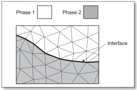
Early approaches to simulating biphasic flows involved the use of separate networks with boundaries for each phase, using a Lagrangian diagram where the Lagrangian method allows an alternative moving lattice to follow phase boundaries during interface deformation as shown in Figure 5 [13].
Figure 5. Lagrangian moving-mesh method
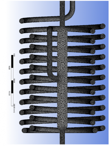
The numerical solution grid used to simulate the flow inside the water-steam pipes of the steam generator is shown in Figure 6. Table 4 the shown number of cells resulting from the mesh generation of the numerical solution for both the waterside and the fireside. Which was approved based on the performance of the flow simulation. A mesh sensitivity analysis was performed to ensure the independence of the numerical mesh of the simulation results to represent the flow in the steam generator. The network independence was evaluated by calculating the percentage change that is less than (1%) and for the smallest number of cells.
Figure 6. The numerical solution grid for Water-Vapor side
Table 4. Mesh statistics
|
Assembly |
Node |
Element |
|
|
Water-Vapor side |
331,103 |
1,524,983 |
|
|
Fireside |
Without partition |
777,104 |
4,190,666 |
|
With one partition |
803,959 |
4,194,438 |
|
|
With two partitions |
806,487 |
4,175,162 |
|
a) The characteristics of the water used are the same as standard pure water, which will be used in the boiling temperature and pressure of water calculations in addition to the specific heat.
b) Without heat transfer from equipment to the atmosphere and vice versa, all heat transferred is inside the system only.
c) Metals used in equipment manufacturers' steam generators are standard materials.
A review of the results obtained from the simulation of heat transfer and fluid flow inside the steam generator for both sides (fireside and water steam side) clearly show the effect of adding circuit breakers inside the steam generator.
4.1 Water-Vapor side
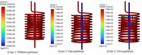
The results of simulating heat transfer inside the tubes of the inner coil, the outer coil, and the central vertical cylinder for the three cases showed that the flow inside the outer coil tube remains in the liquid phase despite the high temperature. Despite the high temperature in the first case (without partition), while it remains below the boiling point. In the second and third cases (one partition and two partition), the temperature exceeds the boiling temperature of the water, and it begins to turn into steam before entering the vertical cylinder (see Figure 7 for the density distribution and Figure 8 for the temperature distribution).
In the first case, the water remains in the liquid phase in the internal coil, despite the high temperature, but it is below the required level to form steam. In the second and third cases, we notice the water turning into steam at the end of the coil, and it is earlier in the third case compared to the second case, and then all of it turns into steam, while in the first case, the water remains in the liquid phase.
4.2 Fireside
Figures 9 and 10 show the apparent effect of adding Partition walls inside the fireside of the steam generator in each of the two cases (one Partition and two Partitions), where we note that the path of hot air near the tubes of the external coil is better than it is in the first case (without Partition) and resulting from Forcing the hot air to follow the new path before leaving the steam generator, in turn, led to a significant increase in the convection heat transfer coefficient. This coefficient depends on the flow rate and the air temperature, as well as an increase in the mass of the heated air, and thus an increase in the amount of heat transferred by the convection because it depends mainly on the coefficient of heat transfer within the system in addition to the temperature difference.
As for the inner coil, we noticed an improvement in heat transfer as happened in the outer coil, but the difference in this case is that in the second case (there is a partition between the inner and outer coils only) is that the speed of hot smoke flowing around the coil is gradual from a region with a slow velocity (at the top of the coil because of the state of stagnation (almost) to an area of good velocity at the bottom of the coil (the area where the air is moves to the external coil) and this in turn led to the heat transferred in this case being slightly less than the third case in which there is a partition between the vertical cylinder and the coil The internal, because the air path in the third case is almost equal along the inner coil, but the second case remains better in terms of heat transfer than the first case in which the direction of the hot air is parallel to the vertical cylinder, and therefore the air speed near the coils is very low, which led to The steam generator should have a lower thermal efficiency compared to the second and third cases.
Figure 7. Water-Vapor side density distribution
Figure 8. Water-Vapor side temperature distribution
Figure 11 shows the vectors and velocity of the hot air inside the steam generator around the vertical cylinder, the inner coil and the outer coil) in each of the three test cases. It shows the effect of the partition on the air distribution around the pipes. Table 5 shows the main parameters (Reynolds numbers, Prandtl numbers and Nusselt numbers) obtained for the outer coil, inner coil and vertical cylinder by representing the hot air flow inside the steam generator.
Figure 9. Fireside (Hot air temperature distribution)
Figure 10. Fireside (Hot air velocity magnitude)
Figure 11. Fireside velocity path lines
Table 5. Result of parameters calculation
|
Type of Tube |
Reynolds Numbers |
Prandtl Number |
Nusselt Number |
Area (m2) |
|
|
Case 1: No Partition |
Vertical Cylinder |
157,894.7368 |
0.694 |
233.599 |
0.0638 |
|
Inner Coil |
2,127.6596 |
0.68 |
21.350 |
0.3306 |
|
|
Outer Coil |
1,463.4146 |
0.68 |
17.933 |
0.4007 |
|
|
Case 2: One Partition |
Vertical Cylinder |
69,230.7692 |
0.697 |
154.904 |
0.0638 |
|
Inner Coil |
1,395.3488 |
0.691 |
17.633 |
0.3306 |
|
|
Outer Coil |
1,690.1408 |
0.685 |
19.225 |
0.4007 |
|
|
Case 3: Two Partition |
Vertical Cylinder |
115,384.6154 |
0.697 |
199.980 |
0.0638 |
|
Inner Coil |
2,903.2258 |
0.683 |
24.713 |
0.3306 |
|
|
Outer Coil |
2,352.9412 |
0.681 |
22.386 |
0.4007 |
|
Figure 12. Heat transfer convection coefficient value
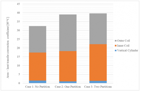
The results of calculating the heat transfer coefficient by convection are shown in Figure 12 for each of the three cases, for each part separately. It is noted in these results that the best heat transfer coefficient by convection for the vertical cylinder is in the first case (No Partition) because the hot air flow, in this case, is stable and has a good speed along the cylinder.
The separating walls on both sides of the outer coil improve the convective heat transfer coefficient higher in the third case compared with the other. The convective heat transfer coefficient of the Inner coil was the best possible in the second case because of the high flow rate of hot air and temperatures.
A comparison of the results of the convective heat transfer coefficient inside the steam generator should be made for each pipe area multiplied by the heat factor of each pipe. This comparison showed that the best values of the overall heat transfer coefficient are in the third case (two partitions) compared to the rest, see Figure 13.
Figure 13. Contact area and heat transfer convection coefficient value
Although the current work is a theoretical study, the present design of the steam generator represents part of an integrated system that has been thoroughly manufactured. This design showed better performance in generating steam in the presence of a partition compared to the absence of a partition.
In this study a coupled thermal analysis model for steam generators containing a helical coil and vertical separator in the core with partition. Using CFD model of the flow and heat transfer process for a steam generator. The temperature field on the inner wall of the helical tube obtained from the thermal analysis model is used as input to analyze the flow and heat transfer characteristics of the fluid in the helical tube. The following conclusions are drawn based on the calculation: results.
It is possible to conduct a study on the effect of using tubes with fins instead of smooth pipes, which is one of the most prominent solutions worked enhancing heat transfer. It is also possible for the partition to be placed in contact with the tubes of the coils and not to leave any distance between them, which will work for the hot air to take a path parallel to the pipes of the internal and external coils and the direction of the hot air flow is opposite to the direction of the water flow inside the tubes along the tube this, in turn, may improve transmission The heat is due to increasing the path that the hot air takes before leaving the steam generator, thus increasing the depletion of thermal energy as much as possible.
|
CFD |
computational fluid dynamics |
|
LPG |
Liquefied petroleum gas |
|
A |
Cross-sectional area $\mathrm{m}^2$ |
|
D |
Diameter mm |
|
m |
mass flow rate kg.s-1 |
|
Nu |
Nusselt number |
|
P |
Pressure bar |
|
Pr |
Prandtl number |
|
R |
Universal gas constant J.kg-1.K-1 |
|
Re |
Renault number |
|
T |
Temperature K |
|
V, U |
Velocity m.s-1 |
|
L |
Length m |
|
t |
Time s |
|
h |
The heat transfer coefficient W.m-2.C-1 |
|
h |
Enthalpy J |
|
E |
Energy J |
|
Q |
Heat J |
|
Cp |
Specific heat capacities at constant pressure J.kg-1.K-1 |
|
Greek letters |
|
|
$\gamma$ |
Isentropic expansion |
|
$\rho$ |
Density kg.m-3 |
|
$\sigma$ |
The Stefan-Boltzmann constant |
|
$\mu$ |
The dynamic viscosity kg. m-1.s-1 |
|
$\varepsilon$ |
The emissivity |
|
$\eta_{\text {furn }}$ |
Furnace thermal efficiency |
[1] Jaya, A., Kolmetz, K. (2011). KLM technology group practical engineering guidelines for processing plant solutions KLM Technology Group #03-12 Block Aronia, Jalan Sri Perkasa 2 Taman Tampoi Utama 81200 Johor Bahru Malaysia BOILER (ENGINEERING DESIGN GUIDELINE). https://www.klmtechgroup.com.
[2] Baukal, C.E. (2012). The John Zink Hamworthy Combustion Handbook, Second Edition: Volume 1 – Fundamentals. CRC Press Taylor & Francis Group. https://doi.org/10.1201/b11619
[3] Yu, X., Sun, B.Z., Li, Y.J., Shi, J.X., Zhang, G.L., Wu, W.Z., Zhao, Z.R. (2019). Numerical investigation of thermal-hydraulic parameter distribution characteristics during dryout evolution in the helically coiled once-through steam generator. International Journal of Heat and Mass Transfer, 139: 373-385. https://doi.org/10.1016/j.ijheatmasstransfer.2019.05.034
[4] Haryoko, L.A.F., Kurnia, J.C., Sasmito, A.P. (2022). Forced convection boiling heat transfer inside helically-coiled heat exchanger. IOP Conference Series: Earth and Environmental Science, 463(1): 1-6. https://doi.org/10.1088/1755-1315/463/1/012030
[5] Mahvelati, E.A., Forcinito, M., Fitschy, L., Maesen, A. (2022). Three-dimensional CFD model development and validation for once-through steam generator (OTSG): Coupling combustion, heat transfer and steam generation. ChemEngineering, 6(2): 23. https://doi.org/10.3390/chemengineering6020023
[6] Riyandwita, B.W., Awwaludin, M, Krismawan, Zacharias, P., Siswanto, E., Setiawan, P.H., Nugroho, A. (2019). Analytical design of helical coil steam generator for hot temperature gas reactor. Journal of Physics: Conference Series, 1198(4): 042014. https://doi.org/10.1088/1742-6596/1198/4/042014
[7] da Silva, J.A.M., Ávila Filho, S., Carvalho, M. (2017). Assessment of energy and exergy efficiencies in steam generators. Journal of the Brazilian Society of Mechanical Sciences and Engineering, 39(8): 3217-3226. https://doi.org/10.1007/s40430-016-0704-6
[8] Kang, J., Rong, Y. (2006). Modeling and simulation of load heating in heat treatment furnaces. Journal of Materials Processing Technology, 174(1-3): 109-114. https://doi.org/10.1016/j.jmatprotec.2005.03.037
[9] Drosatos, P., Nikolopoulos, N., Kakaras, E. (2019). An in-house built code incorporated into CFD model for the simulation of boiler’s convection section. Fuel Processing Technology, 202: 106333. https://doi.org/10.1016/j.fuproc.2019.106333
[10] Wu, S.F., Li, Z.H., Wang, P.F., Su, G.H., Wan, J.S. (2023). A three-region movable-boundary helical coil once-through steam generator model for dynamic simulation and controller design. Nuclear Engineering and Technology, 55(2): 460-474. https://doi.org/10.1016/j.net.2022.10.005
[11] Yao, H., Chen, G., Lu, K.L., Liao, H.Y., Wu, Y.W., Tian, W.X., Su, G.H., Qiu, S.Z. (2021). Study on the thermal and geometrical parameters of helical coil once-through steam generator system. International Journal of Advanced Nuclear Reactor Design and Technology, 3: 80-96. https://doi.org/10.1016/j.jandt.2021.07.001
[12] Cengel, Y.A. (2002). Heat Transfer a Practical Approach, 2nd Edition. McGraw – Hill.
[13] Zhang, Y., Li, Q., Zhou, H. (2016). Theory and Calculation of Heat Transfer in Furnaces. Elsevier Inc.
[14] Malalasekera, W., Versteeg, H.K., Henson, J.C., Jones, J.C. (2002). Calculation of radiative heat transfer in combustion systems. Clean Air, 3(1): 113-143. https://doi.org/10.1080/15614410211849
[15] Kharangate, C.R., Mudawar, I. (2016). Review of computational studies on boiling and condensation. International Journal of Heat and Mass Transfer, 108: 1164-1196. https://doi.org/10.1016/j.ijheatmasstransfer.2016.12.065