Messaoud Kermiche*![]() | Ammar Abdelli
| Ammar Abdelli![]() | Nassim Sayoud
| Nassim Sayoud![]() | Hocine Sissaoui
| Hocine Sissaoui![]()
© 2024 The authors. This article is published by IIETA and is licensed under the CC BY 4.0 license (http://creativecommons.org/licenses/by/4.0/).
OPEN ACCESS
This research focuses on the influence of water turbidity on the thermal efficiency of solar ponds, innovative devices designed for the concurrent collection and storage of solar energy utilizing salinity gradients. A three-dimensional simulation approach is employed to analyze solar ponds under varying turbidity conditions, namely clear, slightly turbid, and very turbid water. The findings reveal that increased turbidity levels lead to reduced solar radiation penetration, consequently decreasing the temperature in the pond's bottom storage zone. Notably, the presence of a temperature profile across horizontal planes in solar ponds, as identified in this study, challenges the adequacy of conventional one-dimensional models in explaining certain phenomena. This insight casts doubt on the widely accepted concept of distinct upper and lower convective zones within solar ponds, suggesting a need to re-evaluate this hypothesis. Moreover, the ground beneath solar ponds is posited as a potential secondary heat storage zone. The study proposes the strategic placement of heat exchangers in the central circular ground plane, just beneath the bottom of the pond. This positioning is recommended to optimize heat extraction efficiency while circumventing the placement of exchangers in the corrosive Lower Convective Zone (LCZ), thereby reducing maintenance costs. The findings underscore the necessity of considering three-dimensional aspects in solar pond analyses for a more comprehensive understanding of their thermal behavior.
solar pond, water turbidity, three-dimensional numerical simulation, finite element method, salinity gradient, thermal efficiency, energy conservation, lower convective zone (LCZ)
In the last twenty years, humankind has become aware of the ineluctable fossil fuel depletion that has become a growing concern over the last twenty years due to their non-renewable nature and the adverse consequences of their burning. According to research based on 2015 data, the current estimates for when our reserves will be emptied are approximately 51 years for oil and 114 years for coal. However, these estimates are subject to change as new reserves are discovered, and the exact date of depletion remains unknown [1, 2]. The combustion of fossil fuels, such as coal, oil, and natural gas, releases harmful gases and soot into the environment, leading to air and water pollution [3].
It also contributes to climate change, resulting in increased temperatures, precipitation, and extreme weather events, which can have severe health impacts, particularly on vulnerable populations. Furthermore, air pollution from the burning of fossil fuels can cause a range of health issues, including respiratory diseases and cancer, and also have a detrimental effect on the environment [4]. As a result, there is a growing need to transition away from fossil fuels towards cleaner, renewable energy sources.
Researchers continuously work on developing alternative resources through new and renewable energy. Solar energy is the most important form of all other available renewable energy. All other forms of renewable energy depend on it. Solar energy's main advantage is that it is harmless with respect to the environment. Many systems, like photovoltaic or solar heating devices, capture solar energy for immediate use but do not have the ability to store it for a long period of time with cost effectiveness. A solar pond is an integrated system that simultaneously collects and stores solar energy with the help of an imposed salt gradient, which constitutes stratified layers [5].
A solar pond is composed of three stacked zones, as indicated in Figure 1:
- An upper convective zone (UCZ) with a low salt concentration;
- A salinity and temperature gradient zone located between the upper and lower zones, namely the non-convective zone (NCZ);
- A lower salt-saturated zone, namely the LCZ, or thermal storage zone.
Initially, the solar rays entering the solar pond will be absorbed by water. These rays will largely be transformed into heat energy and therefore heat up the mass of water in the basin.
The latter, being formed of different zones, will behave differently from a convective pond, where natural convection ensures uniform temperature throughout the pond. The salinity gradient of the solar pond is thus the place of two opposite actions. The first is the effect of temperature, which dilates the liquid at the bottom of the pond, thus decreasing the density and favoring buoyancy. The second is that liquid density increases as salinity itself increases, so natural convection currents will not occur. Therefore, the thermal energy converted becomes trapped in the LCZ. It is from this zone that heat will be extracted to be used in various applications such as the production of electricity, desalination, heating and air conditioning, etc.
A solar pond with an exposed surface to environmental conditions such as rain and wind that carry dust can have a negative impact on the transparency of the water.
Water turbidity is the measure of the relative clarity of a liquid, which depends on the amount of suspended particles in the water. Higher turbidity means more solar radiation scattering, meaning less solar light penetration under water. Clear water increases the amount of radiation that reaches the storage zone at the bottom (LCZ), where, solar energy transforms into heat energy. The blackened liner in contact with water in LCZ absorbs the heat energy and keeps it as sensible heat in this zone. Ensuring a great amount of radiation penetration through water toward the pond bottom is essential to achieving higher energy collection and, hence, a higher temperature. Therefore, water turbidity influences the thermal performance of a solar pond.
Studying the impact of water turbidity is crucial to improving the thermal performance of the solar pond because it directly affects the amount of radiation that reaches the storage zone (LCZ).
Few studies studying the water turbidity effect on solar pond performance have been carried out. Wang6 found that water clarity measured as turbidity level plays a crucial role in the solar radiation amount reaching the storage zone (bottom of the pond).
Wang and Seyed-Yagoobi in 1995 [6] studied how water turbidity affected a solar pond's thermal efficiency and gave an empirical correlation that relates water turbidity to solar radiation attaining a certain depth.
Hull et al. [7] observed the combined impact of bottom reflectivity and water turbidity on the thermal efficiency of a salt gradient solar pond and discovered that, to a certain extent, turbidity compensates for the reflectivity effect.
Researchers of Li et al. [8] were particularly interested in the microorganisms that may reproduce in high-salinity water and affect turbidity. They investigated how well the alum KAl(SO4)2.12H2O worked to control their growth in the brine obtained from the seawater desalination unit.
In the study of Malik et al. [9], various salts were employed to compare their responses to turbidity. They employed a NaCl and MgCl2 combination known as bittern.
It's fundamental to remember that practically all studies on turbidity in solar ponds take the transient thermal behavior of 1D models into account [10]. In other words, only the depth direction is subjected to heat transfer, which is problematic because in authentic solar ponds, heat conduction occurs in all three directions.
Ben Mansour’s numerical solution [11] to the 3D heat conduction equation of a solar pond's transient thermal behavior is reported in. Despite the solar pond's simple geometric structure (a parallelepiped), they employed the Ansys Fluent software, whose resolution is based on the finite volume method. Furthermore, because of the unrealistic boundary conditions at the pond walls, the insulation was assumed to be adiabatic. The turbidity level is not taken into account by their unreliable and simplistic solar radiation attenuation model.
Turbidity is fundamentally one of the most significant variables limiting the operational cost of solar ponds. It has a detrimental effect on the solar pond's thermal efficiency.
The objective of these studies is to know whether the introduction of the 3D model can reveal some aspects that cannot be shown by the majority of preceding studies, especially the turbidity effect, fill some gaps found without the use of 3D formulation, and hence give some recommendations for improving the salt gradient solar pond thermal performance.
Three levels of turbidity have been selected and studied numerically. The boundary conditions are close to those in real-world solar ponds, where soil is the external insulation medium that helps minimize heat losses. Additionally, a model for attenuating solar radiation that accounts for pond turbidity is being examined.
The studied pond consists of a paralellipedic excavation of 7m×7m×2m, with the evolution of the temperature profile simulated numerically over a period of 30 days with three case solar ponds of identical geometry but with different turbidity levels: Relatively clear water (0.5 NTU), slightly turbid (1.5 NTU) water, and very turbid water (4 NTU) (Figure 2).
Figure 1. Three zones in the salt gradient solar pond
Figure 2. Real solar pond constructed at Annaba University (7 m×7 m×2 m)
The mathematical model described below is based on the following assumptions:
The pond geometry is a parallelepiped cavity of size (7m×7m×2m), filled with salt water at different levels of salinity. The fluid is supposed Newtonian weakly compressible. Turbidity is assumed to be uniform. The physicochemical parameters of the fluid vary with the depth z
2.1 Mathematical description of the solar pond
In this work, a three-dimensional numerical model has been presented where the dynamics of the solar pond with salinity gradient is described in terms of 2 main variables namely: temperature and pressure and solved using FEM method.
Density, heat capacity and thermal conductivity depend on temperature and concentration. Due to the complexity of the solution, this numerical model is given in the form of three sub-problems represented in the form of three fundamental equations.
FEM (Finite element method) is a numerical technique for solving differential equations that arise in engineering and mathematical modeling. FEM is suitable for addressing problems that involve especially polygonal geometries, material properties, boundary conditions, and heat sources. FEM works by dividing a large system into smaller, simpler parts called finite elements, and then approximating the unknown function over each element. This reduces the problem to a system of algebraic equations that can be solved efficiently using computers and user friendly commercial software like COMSOL Multiphysics. FEM converge faster than finite volume method FVM another method generally used in Fluid dynamics problem when geometries are complex, so because in our case the geometry is orthogonal (Parallelipedic) FEM is the best choice to reduce the computational cost.
Three cases of the same solar pond of geometry size (7m×7m×2m). Each studied case contains the same salt (NaCl) but with different turbidity levels: relatively clear water (0.5 NTU), slightly turbid water (1.5 NTU) and very turbid water (4 NTU). Turbidity in this paper is symbolized as θ and is found throughout all equations below.
NTU stands for a nepheliometric turbidity unit (NTU) is a unit of measurement for the turbidity or cloudiness of a water, It is based on the amount of light that is scattered by the suspended particles in the fluid at a 90° angle from the incident light source. The higher the NTU value, the more turbid or dirty the water is.
Nephelometers are instruments that measure the turbidity of a fluid using the nephelometric method. They consist of a light source, a detector, and a sample chamber. The light source emits a beam of light that passes through the sample chamber, where the fluid is contained. The detector measures the intensity of the light that is scattered by the particles in the fluid at a 90° angle from the light source. The ratio of the scattered light to the incident light is proportional to the turbidity of nepheliometric turbidity unit which mesure dispersion of light.
The mathematical model described below is based on the following assumptions:
The pond geometry is a parallelepiped cavity of size (7m×7m×2m), filled with salt water at different levels of salinity. The fluid is supposed Newtonian weakly compressible. Turbidity is assumed isotropic. The physicochemical parameters of the fluid vary with the depth z.
2.2 Mathematical description of the solar pond.
In this work, a three-dimensional numerical model has been presented where the dynamics of the solar pond with salinity gradient is described in terms of two main variables namely: Temperature and pressure.
Density, heat capacity and thermal conductivity depend on temperature and concentration. Due to the complexity of the solution, this numerical model is given in the form of three sub-problems represented in the form of three fundamental equations.
Governing equations:
The energy conservation equation is written:
$\rho C_P \mathbf{u} \cdot \nabla \mathrm{T}-\mathrm{k} \cdot \nabla^2 T=-\frac{d E(\theta, z, t)}{d z}$ (1)
The momentum conservation equation:
$\rho \frac{\partial \mathbf{u}}{\partial \mathrm{t}}+(\mathbf{u} \cdot \nabla) \mathbf{u}=\nabla \cdot\left[-\mathrm{p} \mathbf{I}+\mu\left(\nabla \mathbf{u}+(\nabla \mathbf{u})^{\mathrm{T}}\right)-\right.\left.\frac{2}{3} \mu(\nabla \cdot \mathbf{u}) \mathbf{I}\right]+\mathbf{F}+\rho \mathbf{g}$ (2)
The mass conservation equation:
$\rho \frac{\partial \mathbf{u}}{\partial \mathrm{t}}+\nabla(\rho \mathbf{u})=0$ (3)
The specific heat CP, density ρ, and the thermal conductivity k of NaCl depend on temperature as well as concentration.
Initial conditions:
At t=0:
$\mathbf{T}(\mathbf{x}, \mathbf{y}, \mathbf{z}, \mathbf{0})=T_a$ (4)
where, Ta is the constant ambient temperature and is taken equal to 25℃.
Boundary conditions:
z1, z2 and z3 are given in Figure 1.
i. At the surface plane z=z1:
$-\mathbf{n} \cdot \mathbf{q}=q_0$ (5)
where, $q_0=h\left(T_{e x t}-T\right)$.
ii. At the pond bottom there is presence of an inward heat flux due the absorption of the incoming solar radiation Qb:
$-\mathbf{n} \cdot \mathbf{q}=Q_b$ (6)
$Q_b=\mathrm{E}_{\mathrm{s}} *[1-0,1975 \cdot(\theta-0,3)+0,0144\cdot\left.(\theta-0,3)^2\right] \cdot[0,58-0.076 \cdot \ln (100 \cdot z)]$ (7)
where, ES represents the insolation entering at the pond surface.
iii. At the lateral walls:
$\left\{\begin{array}{l}x=-3.5 m \\ x=+3.5 m\end{array}\right.$ and $\left\{\begin{array}{l}y=-3.5 m \\ y=+3.5 m\end{array}\right.$
there is an outward conductive heat losses Qsoil toward soil:
$Q_{\text {soil }}=-k_{\text {soil }} \frac{d T}{d x}$ (8)
iv. On all the walls of the pond, the components of the speed vector U=V=W=0 because of impermeability and non slip condition.
where, ksoil is the soil material thermal conductivity [12].
k represents the thermal conductivity of the water.
2.3 Model for solar radiation
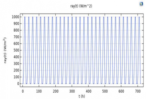
The instantaneous solar radiation Es coming to pond surface was supposed the be a periodic function of the radiation intensity that has been measured locally every 3h for 24 h and then extended to 30 days and is plotted in Figure 3.
The absorption of solar radiation E by the pond is given by [10]:
$\mathrm{E}(\theta, x, t)=\mathrm{E}_s(\mathrm{t}) \cdot \mathrm{H}(\theta, z)$ (9)
$\mathrm{E}_{\mathrm{s}}(\mathrm{t})=\mathrm{E}_{\mathrm{i}}(\mathrm{t}) \cdot(1-\mathrm{r})$ (10)
$r=0.5\left[\frac{\tan ^2\left(\theta_i-\theta_r\right)}{\tan ^2\left(\theta_i+\theta_r\right)}+\frac{\sin ^2\left(\theta_i-\theta_r\right)}{\sin ^2\left(\theta_i+\theta_r\right)}\right]$ (11)
where, Es(t) represents the solar radiation reaching the pond surface.
H(θ,z) is the transmission function (non dimensional).
z is the depth.
$\mathrm{H}(\theta, z)=h(0.3, z) \cdot \mathrm{R}(\theta, z)$ (12)
$\mathrm{h}(0.3, z)=0.58-0.076 \cdot \ln (100 z)$ (13)
$\mathrm{R}(\theta, z)=1-0.1975 \mathrm{z}(\theta-0.3)+0.0144 \mathrm{z}(\theta-0.3)^2$ (14)
with 0.3<θ<5 NTU and 0<z<2 m, where, NTU is the unit of turbidity.
It is important to note that h (0.3, z) represents the reference transmission function based on a turbidity level of 0.3 NTU and R (θ, z) is the ratio of the dimensionless function to a level of turbidity reference.
Here, it is assumed that the relatively clear water corresponds to θ=0.5 NTU, slightly turbid water corresponds to θ=1.5 NTU and very turbid water corresponds to θ=4 NTU, where, NTU is the unit of turbidity.
Figure 3. Solar radiation variation during 30 days
2.4 Numerical details
The solar pond water geometry shown in Figure 5 is constructed using 3 superposed parallelepipeds each one represents a zone (UCZ, NCZ, LCZ) with square face of 7 m length and the depth of each one corresponding to the specific zone.
The whole preceding group are surrounded by greater cube representing the soil of 10 m of edge length as represented in Figure 4.
Figure 4. Solar pond concentration and temperature gradients and different insolation, heat losses
Finite element method consists in approaching a finite dimensional subspace of a problem written in variational form in an infinite dimensional space. After having cut the space into small domains called finite elements, the approximate solution will be given in certain regions called the mesh elements.
Figure 5. The geometry used into the simulation
The advantage of the finite element method is that it makes it possible to converge rapidly giving more precise solutions for fine meshes, but in return, this finer mesh increases the calculation time and hence the needed memory, where the need to use a powerful computer.
Comsol software uses the time depedent solver for solving the system of Eqs. (1), (2), (3). and the constructed mesh is of free tetrahedral elements as shown in Figure 4.
Free tetrahedral elements are a type of mesh that can be used to discretize the domain for solving heat conduction problems. They have some advantages over other types of mesh, such as:
These advantages make free tetrahedral elements a suitable choice for heat conduction problems with complicated shapes, heterogeneous materials, and high gradients.
Comsol Multiphysics uses the finite element method, Comsol software is a multiphysics simulation platform that allows us to couple different physics phenomena, such as fluid flow, heat transfer, salinity transport, and solar radiation, in a unified framework. The advantages of using Comsol software for solar pond simulations are:
If our choice fell on this method it is on the one hand well adapted to our problem and gives many values in many points of the mesh, and on the other hand it accelerates convergence of the basic iterative method and reduces errors. The computer used with the following features: (Intel R Core i5 CPU TM 2400S has 2.5 GHZ and 8 GB RAM). Was used to solve the governing equations.
3D model and temperature profile
Figure 6 gives the 3D temperature profiles as function of different turbidity levels.
Figure 6. The mesh used in this simulation
It is evident from Figure 7 that turbidity has a significant role in lowering the temperature of the storage zone, indicated in the figure by the inferior rectangle in the cutplane the one that is hotter than other regions. The control of turbidity level in solar pond is à key operation that maximize its thermal performance as it prevents solar radiation to reach the solar pond bottom, which transforms it into heat by radiation absorption.
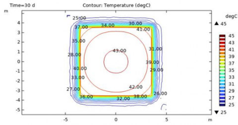
Figure 8 shows the temperature distribution at the horizontal cutplane that contains the solar pond bottom. Engineers blacken the bottom of the solar pond to absorb solar radiation; the liquid of the lower convective zone becomes hotter as it absorbs heat from the blackened bottom plane, making it the hotter plane in the pond. This creates a circular contour of equal temperatures, reaching 47 degrees Celsius (43 in relatively clear water) in the case of clear water, the temperature decreases as we move away from the center of the pond and towards the square wall. Beyond the wall, in the soil zone, the temperature is low and does not exceed 26 degrees Celsius. This is because the soil acts as an insulator. The majority of earlier works used 1D models that did not observe this distribution. The temperature in those models depended only on the z dimension.
(a)
(b)
(c)
Figure 7. 3D Temperature profile in three case of turbidity: (a) relatively clear (0.5 NTU), (b) slightly turbid (1.5 NTU) and (c) very turbid water (4 NTU)
It is also observed that temperature increases as the depth z is greater but it changes its profile into nearly linear shape in the lower convective zone this behavior is also not conventional in 1D models that consider the lower convective zone as isothermal zone, deeper than the bottom of solar pond at the soil zone the temperature decrease as this zone is solid conductive zone.
(a)
(b)
(c)
Figure 8. Temperature cantour at horizontal cutplane z=-2m corresponding to solar pond bottom
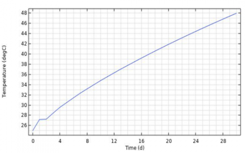
Compared to the other cases of turbidity, the relatively clear water pond with a turbidity level of 0.5 NTU becomes sufficiently hot in a short time for exploitation; this is clear in Figure 9.
The ground zone in a salt gradient solar pond plays a crucial role in storing heat, with its temperature and warm-up period significantly influenced by ground conditions, (Chakrabarty s.d.) [13] both highlighted the significant impact of ground conditions, such as the depth of the water table and the thermal conductivity of the soil, on the storage zone temperature and heat losses in the pond. These findings suggest that a deeper understanding of the temperature decrease in the soil zone beyond the pond walls could enhance the overall understanding of the thermal behavior in salt gradient solar ponds. The ground beneath the pond also contributes to its heat storage capability, with factors such as the depth of the underground water table and the thermal properties of the soil affecting heat loss and recovery rate [14].
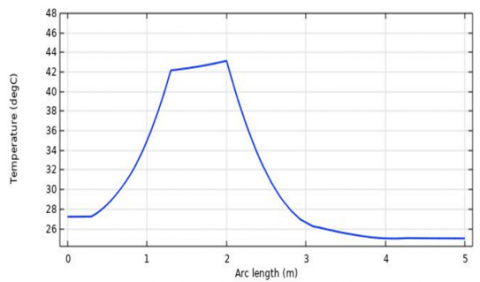
In this study, the temperature profile in the ground zone, Figure 10, shows that nearly 1 m of temperature gradient exists, and this heated soil can play a role as a second storage zone. Figure 8 shows that it is preferred to place the heat exchanger into a circular hotter plane just beneath pond bottom to extract heat, rather than placing it in the corrosive salty water of the LCZ, causing a further maintenance cost [15].
(a)
(b)
(c)
Figure 9. 3D time dependent temperature at cutpoint Z=-2m, x=y=0m for different levels of turbidity: A-Relatively clear water (θ=0.5 NTU). B- Slightly turbid water (θ=1.5NTU). C- Very turbid water (θ=4 NTU)
(a)
(b)
(c)
Figure 10. Temperature profile along z cutline x=y=0
Contrary to what many writers have reported that temperature variations only occur along the z depth, this research demonstrates that in authentic solar ponds, temperature vary in all directions. This disagree the fundamental assumption of 1-D models, which claim that the temperature along a horizontal plane is constant. For each horizontal plane.
The turbidity level's impact is remarkably apparent. The radiation penetration power into water is weaker as this level rises, resulting in a lower temperature in storage zone. This is because dust or microorganisms in suspension absorbed some of the radiation. At any horizontal cut plane, the temperature is higher in the center of any horizontal cut plane, for instance, for z=-2m, the maximum temperature obtained for water that is generally clear is 47℃, for water that is slightly turbid it is 43℃, and for highly turbid water it is just 31.00℃. For x=y=0 m coordinates, this heating can alternatively be shown as a 1D vertical Z temperature profile. The temperature rises in the z direction, reaches its peak close to the bottom, then falls in the soil zone. The 3D approach models of actual solar ponds illustrate the significance of how past efforts do not accurately depict the temperature profile.
This finding challenges the concept of the upper and lower convective zones, which require revision because there is no strong convection enough to totally homogenize the temperature in those zones, since temperature changes in all directions.
The ground beneath pond bottom especially those in direct thermal contact with central zone can be the zone of choice to place extracting heat exchanger, avoiding placing them in corrosive salty water of LCZ.
In Figure 10 the temperature is plotted versus 1 D z direction cutline at coordinate x=y=0.
|
Cp |
Specific heat [kJ/kg℃] |
|
E |
Radiation intensity [w/m2] |
|
Cht |
Heat Transfer Coefficient [w/m2℃] |
|
k |
Heat Conductivity Coefficient [w/m℃] |
|
q or Q |
Heat transfer rate[w/m2] |
|
s |
Salinity of the brine [%] |
|
T |
Temperature [℃] |
|
t |
Time [sec] |
|
µ |
Extinction Coefficient of Transmission Function [m-1] |
|
ρ |
Density [kg/m3] |
[1] Shafiee, S., Topal, E. (2009). When will fossil fuel reserves be diminished? Energy Policy, 37(1): 181-189. https://doi.org/10.1016/j.enpol.2008.08.016
[2] Alazard, N., Montadert, L. (1993). Oil resources for the next century: What’s ahead? Nonrenewable Resources, 2: 197-206. https://doi.org/10.1007/BF02257915
[3] Ryemshak, S.A., Ihom, A.P. (2015). The adverse effects of flue-gas emission and carbon-soot from combustion of fossil fuel leading to the phase-out campaign of coal – A review. International Journal of Modern Trends in Engineering.
[4] Sommer, A. (2016). Burning fossil fuels: Impact of climate change on health. International Journal of Social Determinants of Health and Health Services, 46(1): 48-52. https://doi.org/10.1177/0020731415625253
[5] Akbarzadeh, A., Ahmadi, G. (1980). Computer simulation of the performance of a solar pond in the southern part of Iran. Solar Energy, 24(2): 143-151. https://doi.org/10.1016/0038-092X(80)90388-6
[6] Wang, J., Seyed-Yagoobi, J. (1994). Effects of water turbidity and salt concentration levels on penetration of solar radiation under water. Solar Energy, 52(5): 429-438. https://doi.org/10.1016/0038-092X(94)90120-Q
[7] Hull, J.R., Bushnell, D.L., Sempsrote, D.G., Pena, A. (1989). Ammonium sulfate solar pond: Observations from small-scale experiments. Solar Energy, 43(1): 57-64. https://doi.org/10.1016/0038-092X(89)90100-X
[8] Li, N., Yin, F., Sun, W., Zhang, C., Shi, Y. (2010). Turbidity study of solar ponds utilizing seawater as salt source. Solar Energy, 84(2): 289-295. https://doi.org/10.1016/j.solener.2009.11.010
[9] Malik, N., Date, A., Leblanc, J., Akbarzadeh, A., Meehan, B. (2011). Monitoring and maintaining the water clarity of salinity gradient solar ponds. Solar Energy, 85(11): 2987-2996. https://doi.org/10.1016/j.solener.2011.08.040
[10] Wang, J., Seyed-Yagoobi, J. (1994). Effects of water turbidity and salt concentration levels on penetration of solar radiation under water. Solar Energy, 52(5): 429-438. https://doi.org/10.1016/0038-092X(94)90120-Q
[11] Ben Mansour, R., Nguyen, C., Galanis, N. (2004). Numerical study of transient heat and mass transfer and stability in a salt-gradient solar pond. International Journal of Thermal Sciences, 43: 779-790. https://doi.org/10.1016/j.ijthermalsci.2004.02.018
[12] Berkani, M., Sissaoui, H., Abdelli, A., Kermiche, M., Barker-Read, G. (2015) Comparison of three solar ponds with different salts through bi-dimensional modeling. Solar Energy, 116: 56-68. https://doi.org/10.1016/j.solener.2015.03.024
[13] Saxena, A.K., Sugandhi, S., Husain, M. (2009). Significant depth of ground water table for thermal performance of salt gradient solar pond. Renewable Energy, 34(3): 790-793. https://doi.org/10.1016/j.renene.2008.04.040
[14] Zhang, Z.M. (1990). A study on the thermal storage of the ground beneath solar ponds by computer simulation. Solar Energy, 44(5): 243-248. https://doi.org/10.1016/0038-092X(90)90052-E
[15] Leblanc, J., Akbarzadeh, A., Andrews, J., Lu, H.M., Golding, P. (2011). Heat extraction methods from salinity-gradient solar ponds and introduction of a novel system of heat extraction for improved efficiency. Solar Energy, 85(12): 3103-3142. https://doi.org/10.1016/j.solener.2010.06.005