David Mangallo![]() | Joni*
| Joni*![]()
© 2024 The authors. This article is published by IIETA and is licensed under the CC BY 4.0 license (http://creativecommons.org/licenses/by/4.0/).
OPEN ACCESS
Carbonization is a highly energy-intensive process for converting biomass into solid fuel, especially in conventional systems without heat insulators. During the process, heat losses are unavoidable; thus, it is vital for utilizing insulators to minimize the losses. Clay, a naturally abundant and inexpensive material, could be used as an insulator. The corn cob carbonization process is carried out using a used oil drum as a carbonization kilns (reactor), with 200 L capacity and 1.25 mm thickness, by adding a Y-shaped pipe with a diameter of 100 mm in the center of it. The testing procedure involved coating one drum with a 1.5 cm clay insulator and leaving the other drum uninsulated. Each drum was then filled with 21 kg of dried corn cobs. A type K thermocouple is attached to the reactor's side wall and cover, and then connected to a Graphtec type GL240 datalogger for automated temperature measurement and recording. The study and analysis showed that in the absence of insulators, heat losses due to radiation and convection reached 3611.94 W (55.64%) during a 220-minute charcoal production (carbonization process). Meanwhile, when an insulator was used, the heat loss was reduced to 2320.69 W (35.75%) during the 170-minute charcoal production (carbonization process). Therefore, the utilization of clay insulators can result in 14.89% reduced heat losses and 22.73% shorter carbonization time.
carbonization reactors, charcoal production, clay insulators, convection heat, corn cobs, heat effectiveness, heat loss, radiant heat
Corn cobs are a promising organic agricultural byproduct derived from corn harvests. Despite the abundance of this waste, its utilization remains inefficient, resulting in significant wastage. People have conventionally used corn cob waste as animal feed and direct fuel for cooking; therefore, a solution to increase the value of this waste is required. One feasible solution is utilizing corn cobs as a raw material in producing activated carbon [1]. Activated carbon is produced by chemically and physically activating corn cob charcoal. Acid and base solutions are added during the chemical activation process to enhance the surface area of activated carbon pores [2]. Due to its cellulose (39.1%), hemicellulose (42.1%), lignin (9.1%), protein (1.7%), and ash (1.2%) content, corn cobs have the potential to be used as raw materials for producing activated carbon [3]. As indicated by the aforementioned percentage component, the carbon content of corn cobs is very high. The corn cobs contain 43.42% carbon and 6.32% hydrogen and have a calorific value ranging from 4,934 to 6,034 calories per gram [4].
Carbonization is a process that raises the calorific value of biomass, making it easier to ignite while maintaining a clean and environmentally friendly combustion [5]. Carbonization produces charcoal, which is black formed up of carbon. The initial composition of the biomass determines the amount of charcoal produced. Production will decrease as volatile matter content rises due to increased component release into the atmosphere [6]. The carbonization temperature has a significant impact on the charcoal produced; thus, determining the optimal temperature is critical for producing high-quality charcoal [7]. In order to release the tar that makes up about 30% of the charcoal, the carbonization process must eventually reach a temperature of up to 500℃. It should be noted that reaching this temperature requires relatively high thermal energy [8, 9].
The reactor heat loss is measured in the carbonization process by calculating the energy loss in the outer walls during the combustion process. Valentim et al. [10] investigated the thermal performance of cylindrical sidewalls of charcoal kilns made from various materials and configurations. They discovered that implementing the new configuration significantly reduced the duration of heating and cooling, the amount of heat supplied to the sidewalls, and heat loss to the ambient. The energy losses resulting from conduction through the kiln total 10.57% of the supplied energy [11]. Moreover, simulations of char activation rotary kilns indicate that temperature distribution within the kiln is influenced by operational variables, including fuel and feed rate [6]. Furthermore, studies on industrial carbonization processes have shown that using slow heating techniques and maintaining the kiln or reactor temperatures distribute between 500 and 600℃ will produce high-quality charcoal suitable for export [12].
Insulating the charcoal production (carbonization) reactor can reduce heat loss. Clay is a common insulator material [13] that is affordable and environmentally sustainable. The main components of it are phyllosilicate minerals, which include silica, aluminum oxide, calcium, iron, magnesium, and potassium oxide. The Loss on Ignition (LOI) values of the raw material were assessed to be 12.83% at a temperature of 1,010℃ [14]. The objective of this study is to analyze the application of clay insulators in the conventional charcoal-production (carbonization) process, with a particular focus on enhancing the efficiency of charcoal production time and minimizing fuel consumption resulting from heat loss.
2.1 Material
This study uses a repurposed mild stainless-steel drum with 200 L in capacity and 1.25 mm in thickness as a carbonization kilns (reactor). The drum has been modified in terms of its shape and size, as depicted in Figure 1. A 100 mm in diameter and 1.5 mm thick Y-shaped pipe is placed in the center of the reactor and welded into its wall to prevent any potential leaks. To evaluate the reactor's performance as a container for charcoal production, 21 kg of corn cob waste raw material was used in each condition of the reactor, e.g., without and with an insulator. The test uses an insulator made of wet clay with a thickness of 1.5 cm that is attached to the entire outer surface of the reactor.
Figure 1. Construction of the carbonization reactor
The temperature was measured with a type K thermocouple attached to the rector's outer wall and cover. The thermocouple was connected to a Graphtec GL240 data logger to read and record the temperature. The Graphtec GL240 data logger has 10 analog input channels and can sample data at intervals ranging from 0 milliseconds to 1 hour (with a resolution of 10 to 50 milliseconds). It can also display waveforms with a time scale ranging from 1 second to 24 hours per division. The available input voltage options range from 20 to 500 millivolts and from 1 to 100 volts, including both discrete values and a full-scale voltage range of 1 to 5. The humidity range is from 0 to 100% RH. When using a type K thermocouple with a temperature -100<TS≤1370℃, the temperature measurement accuracy is within ± 0.05% of the temperature +1.0℃.
A digital scale with a maximum capacity of 150 kilograms and a precision of 100 grams is used for measuring the weight of raw materials. The carbonization reactor utilizes 40 kg of fuel derived from waste wood chips obtained from the processing site as its heat source.
2.2 Methods
The carbonization process of a 21 kg batch of corn cobs involves the initial step of preparing and removing undesired substances, such as dust or sand, present in the husk openings. The cleaned corn cobs are then transferred to a 200 L capacity reactor that has been pre-prepared and placed in a combustion furnace. The carbonization process in reactors with clay insulation on the outer wall is the same as in reactors without it. Wood pieces weighing 40 kg are then loaded into the combustion chamber as fuel and ignited to heat the reactor (Figure 2).
Figure 2. Carbonization reactor: a. without insulator; b. with clay insulator
To obtain temperature readings in real-time during the carbonization process, a type K thermocouple is connected to a datalogger that stores the collected data. Temperature sensors are strategically positioned on the left, right, and top surfaces of the reactor, as well as in the ambient environment for accurate measurement. The sensors are referred to as T1, T2, Tp, and T∞, respectively.
Heat transfer from the reactor chamber to the outer wall and cover is examined using radiation and convection. Convective heat transfer mechanism, however, is assumed as negligible because it is very minimal and has no significant effect on heat transfer process [15]. A heat loss analysis was conducted on the carbonization reactor under two conditions: without insulators and with clay insulators applied to the outer wall, with a thickness of 1.5 cm, to prevent heat loss. Reactor testing was carried out for each corncob carbonization process, and the average temperature increase was recorded. The process to estimate heat transfer losses involves calculating the physical property of air, i.e., thermal conductivity, kinematic viscosity, and Prandtl number. These properties are obtained by applying Eqs. (1)-(3) to the measured temperature parameters. The dimensionless Nusselt (Nu) and Gasthof (Gr) numbers are computed using Eqs. (5)-(12). The convection coefficients and heat losses are calculated using Eqs. (2) and (6).
2.2.1 Physical properties of air
For the computation of forced and natural air convection coefficients, information regarding the physical properties of air is essential. Therefore, the average air film temperature parameter (Tf) is required to calculate the kinematic viscosity, thermal conductivity, and Prandtl number [16].
-Thermal conductivity of air (k, W/(m℃)) for temperatures ranging from 0 to 1000℃
$\begin{aligned} & k=4.629 \times 10^{-12} T^3-2.520 \times 10^{-8} T^2+\ldots \\ & +7.571 \times 10^{-5} T+0.02364\end{aligned}$ (1)
-Kinematic viscosity of air (v, m2/s) for temperatures ranging from 0 to 1000℃
$\begin{aligned} & v=-1.725 \times 10^{-14} T^3+8.853 \times 10^{-11} T^2+\ldots \\ & +8.947 \times 10^{-8} T+1.329 \times 10^{-5}\end{aligned}$ (2)
-Prandtl number (Pr) for temperatures ranging from 0 to 1000℃
$\begin{aligned} & \operatorname{Pr}=2.916 \times 10^{-13} T^4-8.291 \times 10^{-10} T^3+\ldots \\ & +8.653 \times 10^{-7} T^2-3.387 \times 10^{-4} T+0.7371\end{aligned}$ (3)
2.2.2 Reactor blanket heat loss
The heat loss to the ambient environment during corn cob carbonization is studied using a natural heat transfer approach. Heat loss is transferred through the modified reactor's walls and lid, which are made of repurposed oil drums and 100-mm-diameter Y steel pipes. Heating and combustion occur naturally, with no mechanical means to circulate the surrounding air. As a result, the analysis is carried out using the principles of natural convection and radiation heat transfer, as denoted by Eq. (4) [17].
$q_{\text {loss }}=h A\left(T_s-T_{\infty}\right)+\varepsilon \sigma A\left(T_s^4-T_{\infty}^4\right)$ (4)
where, ε is the surface emissivity (ε = 0.91 for clay and ε=0.85 for mild stainless steel) [18], A is the surface area, and is the Stefan-Boltzmann constant (5.67×10⁻⁸ W/m2. K4).
Assuming that natural convection has negligible fluid motion in comparison to forced convection, the fluid was moved through a density gradient within the fluid due to temperature differences between the fluid and the surface. Due to the low velocity of the fluid, the Reynolds number (Re) can be substituted for the dimensionless Gasthof number (Gr), which possesses both the coefficient of thermal expansion (β) and gravitational acceleration (g).
$\mathrm{Gr}_L=\frac{g \beta\left(T_s-T_{\infty}\right) L^3}{v^2}$ (5)
where, g is the gravitational acceleration, β = 1/Tf the thermal expansion coefficient of the fluid, L is the geometric characteristic length, v is the kinematic viscosity of the fluid, Ts and T∞ are the fluid and ambient temperatures.
Experimental data for natural convection are correlated using the Gasthof, Prandtl, and Nusselt numbers:
$\mathrm{Nu}_L=\frac{h L}{k}=f(G r, P r)$ (6)
where, the Rayleigh number (Ra) is the product of the Gasthof and Prandtl numbers, or:
$\mathrm{Ra}_L=\frac{g \beta\left(T_s-T_{\infty}\right) L^3}{v^2}(\mathrm{Pr})$ (7)
Eq. (8) calculates the ratio of height to diameter (L/D) and the Rayleigh number in relation to the average Nusselt number on a vertical cylinder, where the Prandtl number (Pr) ranges from 0.01 to 100. Because it is based on an exact solution for calculating the laminar free convection of a vertical cylinder in air, this equation is recommended [19].
$N u_L / N u_{L-F P}=1+B\left[32^{0.5}\left(G r_L\right)^{-0.25}\left(\frac{L}{D}\right)\right]^C$ (8)
where, NuL is the average Nusselt number; NuL-FP is the flat plate average Nusselt number; B=0.0571322 + 0.20305 Pr-0.43; and C=0.9165 - 0.0043 Pr0.5 + 0.01333 ln (Pr) + 0.0004809/Pr. This equation is valid for laminar boundary layer areas with the Gasthof number, GrL-cr ≤ 64 × 109. The lower limit calculation is valid if the Rayleigh number (RaL) is ≥104; otherwise, the boundary layer estimate is invalid [20]. The Churchill and Chu correlation equation can be used to cvalculate the average Nusselt number of a vertical flat plate [21].
$N u_{L-F P}=0.68+\frac{0.670 R a_L^{1 / 4}}{\left[1+(0.492 / \mathrm{Pr})^{9 / 16}\right]^{4 / 6}}$ (9)
2.2.3 Reactor cover heat loss
Several studies [22, 23] on natural convection from horizontal plates have been conducted. The correlation equation for a hot surface oriented downwards or a cold surface oriented upwards is as follows:
$\mathrm{Nu}_L=\frac{h L}{k}=0.54 \mathrm{Ra}_L^{1 / 4}$ for $2 \times 10^4<\mathrm{Ra}_L<8 \times 10^6$ (10)
$\mathrm{Nu}_L=\frac{h L}{k}=0.15 \mathrm{Ra}_L^{1 / 3}$ for $8 \times 10^6<\mathrm{Ra}_L<2 \times 10^9$ (11)
Meanwhile, the equation for a hot surface facing up or a cold surface facing down is:
$\mathrm{Nu}_L=\frac{h L}{k}=0.27 \mathrm{Ra}_L^{1 / 4}$ for $10^5<\mathrm{Ra}_L<10^{10}$ (12)
2.2.4 Energy use effectiveness
The ratio of energy lost during the process to the energy used to heat the reactor with wood chip fuel constitutes the effective energy requirement for the carbonization process. This is represented by the following equation [24]:
$\eta_{eff}=1-\left(\frac{Q_{f u e l}-Q_{\text {loss }}}{Q_{f u e l}}\right)$ (13)
From the collected test results and reactor temperature data under varying conditions, it is evident that heat loss within the reactor is an unavoidable result of the corncob carbonization process. This occurrence has an impact on the extended duration of carbonization because the efficiency of heat transfer for accelerating the carbonization process is hampered due to heat loss into the ambient. The application of an insulating material reduces heat loss in the ambient and results in a more efficient carbonization duration. In more precise terms, the carbonization process requires 220 minutes to complete in the absence of an insulator, whereas its utilization shortens the duration by 170 minutes.
3.1 Temperature distribution and physical properties of air during the carbonization process
Temperature measurements were taken at regular 30-minute intervals during the corn cob combustion process in both reactor conditions, i.e., with and without insulators. These measurements were continued until the formation of a charcoal product.
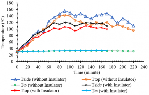
Figure 3. Temperature distribution during the carbonization process
Figure 3 shows the mean temperature distribution for each reactor condition. Higher temperatures have been released into the environment due to the lack of an insulator in the reactor; the average temperatures of the reactor cover and outer surface are 103.57℃ and 108.48℃, respectively. Nevertheless, applying a clay insulator spanning 1.5 cm in thickness across the entire reactor surface reduced the mean temperatures of the reactor cover and outer surface to 88.23℃ and 99.36℃, respectively.
As indicated by the temperature distribution over time intervals, the carbonization process results in a substantial increase in temperature response. The presence of a moderate temperature difference ranging from 15 to 19℃ suggests that the clay insulators used to line the outer wall of the reactor may not be optimal because the water contained in the clay insulator evaporates due to heat transmission during the carbonization process from the walls to the insulator. This condition leads to the formation of cracks in the insulator, which facilitates the escape of heat into the ambient environment and consequently impacts heat loss [10].
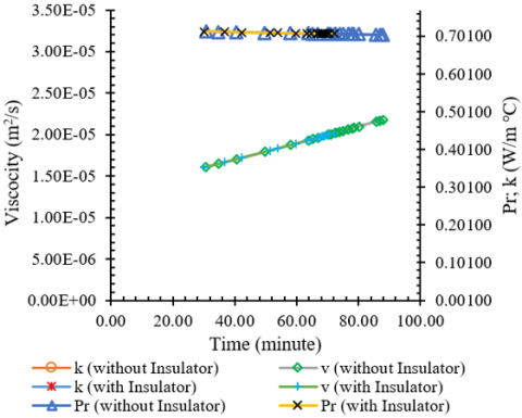
The physical properties of air are significantly impacted by temperature during natural convection heat transfer. It affects the viscosity, thermal conductivity, constant pressure specific heat, density, and the mean free path of air molecules [25]. The amount of heat lost to the environment will be determined by the kinematic viscosity, thermal conductivity, and Prandtl number obtained from film temperature measurements on the wall and cover of the reactor (Figure 4). The maximum kinematic viscosity values on the reactor side and the cover are 2.25×10⁻⁵ m2/s and 2.18×10⁻⁵ m2/s, respectively. The maximum thermal conductivity on the reactor side and the cover is 0.0309 W/m.℃ and 0.0305 W/m.℃) respectively. In the meantime, both Prandtl numbers are 0.7136. The difference in maximum kinematic viscosity and maximum thermal conductivity values demonstrates that temperature influences natural convection heat transfer by determining the physical properties of air.
Figure 4. Air physical properties comparison (k, v & Pr)
3.2 Heat loss in the reactor
The dominant modes of heat transfer in microreactors are conduction and convection, which together contribute to 90% of the heat flux. Meanwhile, radiation only contributes to less than 10% of the heat transfer. However, radiation can constitute a significant proportion of the overall heat transfer in larger wall-heated reactors and can be modeled using the Stefan-Boltzmann law [26]. The total heat transfer of the surface can be calculated by adding the convective and radiative heat transfer coefficients, which results in the equalized heat transfer coefficient. This approach allows for a more accurate application of dimensionless numbers [27]. According to Wakao et al. [28], when Re is less than 10, the heat transfer from particles to the fluid contributes negligibly to the overall increase in heat transfer within the system. As a result, no precise Nu value can be determined. Nu's accuracy is quite high, within the range of 10<Re<100.
Figure 5 shows the heat loss process that occurs during charcoal production, comparing the use of clay insulators with no insulation. It shows that the drum walls experience greater heat loss than the drum cover. This is because the drum wall has a significantly larger surface area for heat transfer than the drum cover [29]. The maximum heat loss occurred at 90 minutes, i.e., 3146.47 W on the drum wall (consisting of convection heat 1,323.95 W and radiation 1,822.53 W) and 465.46 W on the drum cover (consisting of convection heat 198.07 W and radiation 267.40 W). As a result, the total heat loss is 3611.94 W. The heat lost during the carbonization process increases until the 90th minute, then fluctuates and tends to decrease to 1.942.71 W. Using clay insulators, the heat loss reaches a maximum of 2,320.69 Watts, with 285.22 W attributed to cover heat loss and 2,035.48 W attributed to wall heat loss. The heat loss experienced during the carbonization process in the absence of an insulator is higher compared to the heat loss during the carbonization process with insulation. The reason for this is that the temperature of the charcoal production (carbonization) drum, which is covered with a clay insulator, is lower than the temperature of the drum without an insulator. The graph shows that the production time for charcoal from corn cobs is quicker, taking only 170 minutes, compared to 220 minutes for the uninsulated reactor.
Figure 5. Heat loss during the carbonization process
3.3 Energy use effectiveness
The thermal energy generated through the combustion of wood, which serves to heat the reactor, is subsequently transferred to the chamber containing the corn cobs. The transfer of heat occurs via conduction from the bottom of the reactor, leading to a gradual rise in room temperature and subsequent release of steam from the corn cobs. At a maximum temperature of 155.70℃ (reactor without insulator) and 119.80℃ (reactor with insulator), complete decomposition took place, as evidenced by the temperature in the reactor chamber remaining constant and gradually declining between the 90th and 100th minute.
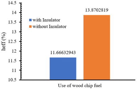
The effectiveness of heat absorption is evaluated by comparing the heat loss during the process to the higher heating value (HHV=234 J/g) of wood chip fuel used in charcoal production [30]. Figure 6 shows the heat loss percentage during the carbonization process, which is 88.33% (reactor without insulation) and 86.12% (reactor with clay insulator). Meanwhile, heat absorption effectiveness reached 11.67% (for reactors without insulators) and 13.87% (for reactors with insulators), as shown in Figure 7. Valentim et al. [10] confirmed the effectiveness of using insulators in carbonization reactors by demonstrating significant reductions in heating time. These reductions ranged from 66.0% to 99.7% when using different configurations of insulators in the reactors. The configurations included: (I) fixed side walls made of AISI 1020 stainless steel, (II) fixed side walls covered with insulators, and (III) a rotating side wall with an insulator coating for the heating stage.
Figure 6. Heat losses for the carbonization process
Figure 7. Effectiveness of heat absorption
It demonstrates that the amount of heat needed for reactor combustion is minimal, while convection and radiation are responsible for a greater amount of heat loss into the ambient environment. The carbonization process of 21 kg of corn cobs in an uninsulated reactor resulted in the production of 10.4 kg of charcoal at a rate of 2.84 kg per hour, resulting in an efficiency of 45.22% rendement. Meanwhile, a total of 21 kg of corn cobs underwent carbonization in a reactor equipped with a clay insulator, resulted in the production of 9.8 kg of charcoal at a rate of 3.46 kg per hour, resulting in an efficiency of 46.67% rendement. Based on the analysis of the two carbonization processes, it is evident that the yield and production capacity of corn cobs carbonized in a reactor coated with a clay insulator are higher than to those carbonized in a reactor without insulation.
Applying a clay insulator to the reactor surface for carbonizing corn cobs reduces heat losses by 35.75% and accelerates the process by 50 minutes (22.72%) compared to an uninsulated reactor. Therefore, the carbonization process could potentially be accelerated and heat loss reduced through the application of an insulator. During the carbonization process, the reactor without an insulator lost the most heat (3,611.94 watts) at 90 minutes. Meanwhile, the reactor with a clay insulator had the highest recorded heat loss of 2,320.69 watts at the 70-minutes. The carbonization yield (rendement) in reactors without an insulator coating was recorded at 45.22%, while the reactor coated with a clay insulator achieved 46.67%. During the carbonization process, the carbonization tool achieved a capacity of 2.84 kg/hour in the absence of an insulator coating. The addition of a clay insulator to the carbonization process resulted in a notable increase in this value to 3.46 kg/hour.
This research was supported by the Institute for Research and Community Service (LPPM) of Cenderawasih University and the Mechanical Engineering Laboratory.
|
h |
heat transfer coefficient, W/ (m2 K) |
|
g |
gravitational acceleration, m/s2 |
|
k |
thermal conductivity, W/ (m. K) |
|
L |
length, m |
|
GrL |
local Grashof number |
|
Pr |
Prandtl number |
|
NuL |
local Nusselt number along the heat source |
|
q |
heat, W |
|
Ra |
Rayleigh number |
|
Re |
Reynold number |
|
Greek symbols |
|
|
α |
thermal diffusivity, m2/s |
|
β |
thermal expansion coefficient, K-1 |
|
e |
emissivity |
|
h |
effectiveness |
|
s |
Stefan-Boltzmann constant |
|
n |
kinematic viscosity, m2/s |
[1] Haslina, Nazir, N., Sampurno, A. (2021). Different drying duration of corncobs powders and its effects on physical, nutritional and phytochemical. International Journal on Advanced Science, Engineering and Information Technology, 11(3): 1232-1238. https://doi.org/10.18517/ijaseit.11.3.15321
[2] Sych, N.V., Trofymenko, S.I., Poddubnaya, O.I., Tsyba, M.M., Sapsay, V.I., Klymchuk, D.O., Puziy, A.M. (2012). Porous structure and surface chemistry of phosphoric acid activated carbon from corncob. Applied Surface Science, 261: 75-82. https://doi.org/10.1016/j.apsusc.2012.07.084
[3] Avila-Segura, M., Barak, P., Hedtcke, J.L., Posner, J.L. (2011). Nutrient and alkalinity removal by corn grain, stover and cob harvest in Upper Midwest USA. Biomass and Bioenergy, 35(3): 1190-1195. https://doi.org/10.1016/j.biombioe.2010.12.010
[4] Rahmawati, S., Pathuddin, Sakung, J., Suherman, Fudholi, A., Sushmita, L. (2020). The utilization of corncob for the manufacture of charcoal briquette as an alternative fuel. Journal of Physics: Conference Series, 1563(1): 012022. https://doi.org/10.1088/1742-6596/1563/1/012022
[5] Sangsuk, S., Suebsiri, S., Puakhom, P. (2018). The metal kiln with heat distribution pipes for high quality charcoal and wood vinegar production. Energy for Sustainable Development, 47: 149-157. https://doi.org/10.1016/j.esd.2018.10.002
[6] Kim, Y.H. (2011). Process simulation of activated carbon production using a rotary kiln. Korean Journal of Chemical Engineering, 28(1): 27-31. https://doi.org/10.1007/s11814-010-0367-4
[7] Mahmoudi, A., Mejri, I. (2015). Isothermal carbonization of wood particle: Application of the lattice Boltzmann method. International Journal of Heat and Technology, 33(2): 129-134. https://doi.org/10.18280/ijht.330221
[8] Lestari, L., Variani, V.I., Sudiana, I.N., Firihu, M.Z., Raharjo, S., Agusu, L., Dewi, A. (2019). Production and characterization of briquette from the activated charcoal of corncob. Journal of Physics: Conference Series, 1153: 012076. https://doi.org/10.1088/1742-6596/1153/1/012076
[9] Joni, Numberi, J.J., Tambing, E., Siregar, S.P., Setiawan, R.P.A., Tambunan, A.H., Siregar, K. (2023). Evaluating the application of bubble wet scrubber systems for gas cleaning in gasification. Instrumentation Mesure Métrologie, 22(10): 21-27. https://doi.org/10.18280/i2m.220103
[10] Valentim, A.R., Behainne, J.R., Junior, A.B. (2022). Thermal performance analysis of materials and configurations for cylindrical sidewalls of charcoal kilns. Energies, 15(16): 5872. https://doi.org/10.3390/en15165872
[11] Guerrero-Goméz, G., Moreno-Gamboa, F., Vera-Duarte, L.E. (2020). Temperature acquisition and heat loss on the wall of an intermittent kiln. Journal of Physics: Conference Series, 1708(1): 012008. https://doi.org/10.1088/1742-6596/1708/1/012008
[12] García-Quezada, J., Musule-Lagunes, R., Prieto-Ruíz, J.A., Vega-Nieva, D.J., Carrillo-Parra, A. (2023). Evaluation of four types of kilns used to produce charcoal from several tree species in Mexico. Energies, 16(1): 333. https://doi.org/10.3390/en16010333
[13] Al-Malah, K., Abu-Jdayil, B. (2007). Clay-based heat insulator composites: Thermal and water retention properties. Applied Clay Science, 37(1-2): 90-96. https://doi.org/10.1016/j.clay.2007.01.001
[14] Farnood Ahmadi, P., Ardeshir, A., Ramezanianpour, A.M., Bayat, H. (2018). Characteristics of heat insulating clay bricks made from zeolite, waste steel slag and expanded perlite. Ceramics International, 44(7): 7588-7598. https://doi.org/10.1016/j.ceramint.2018.01.175
[15] Sakin, M., Kaymak-Ertekin, F., Ilicali, C. (2009). Convection and radiation combined surface heat transfer coefficient in baking ovens. Journal of Food Engineering, 94(3-4): 344-349. https://doi.org/10.1016/j.jfoodeng.2009.03.027
[16] Forsberg, C.H. (2021). Multimode heat transfer. Heat Transfer Principles and Applications, 391-427. https://doi.org/10.1016/B978-0-12-802296-2.00010-X
[17] Çengel, Y.A., Ghajar, A.J. (2020). Heat and Mass Transfer: Fundamentals and Applications (6th ed); McGraw Hill Education: New York, NY.
[18] Bergman, T.L., Lavine, A.S., Incropera, F.P. (2017). Fundamentals of Heat and Mass Transfer (8th ed). John Wiley & Sons: Hoboken, NJ.
[19] Popiel, C.O. (2008). Free convection heat transfer from vertical slender cylinders: A review. Heat Transfer Engineering, 29(6): 521-536. https://doi.org/10.1080/01457630801891557
[20] Popiel, C.O., Wojtkowiak, J., Bober, K. (2007). Laminar free convective heat transfer from isothermal vertical slender cylinder. Experimental Thermal and Fluid Science, 32(2): 607-613. https://doi.org/10.1016/j.expthermflusci.2007.07.003
[21] Churchill, S.W., Chu, H.H.S. (1975). Correlating equations for laminar and turbulent free convection from a vertical plate. International Journal of Heat and Mass Transfer, 18(11): 1323-1329. https://doi.org/10.1016/0017-9310(75)90243-4
[22] Fujii, T., Imura, H. (1972). Natural-convection heat transfer from a plate with arbitrary inclination. International Journal of Heat and Mass Transfer, 15(4): 755-767. https://doi.org/10.1016/0017-9310(72)90118-4
[23] Lloyd, J.R., Moran, W.R. (1974). Natural convection adjacent to horizontal surface of various planforms. Journal of Heat Transfer, 96(4): 443-447. https://doi.org/10.1115/1.3450224
[24] Ayele, L., Eneyew, Y. (2022). Experimental investigation on renovation of locally manufactured electrical cooking stove. Case Studies in Thermal Engineering, 30: 101712. https://doi.org/10.1016/j.csite.2021.101712
[25] Weng, H.C., Chen, C.K. (2008). Variable physical properties in natural convective gas microflow. Journal of Heat Transfer, 130(8): 082401. https://doi.org/10.1115/1.2927400
[26] Flamant, G., Lu, J.D., Variot, B. (1994). Radiation heat transfer in fluidized beds: A comparison of exact and simplified approaches. Journal of Heat Transfer, 116(3): 652-659. https://doi.org/10.1115/1.2910919
[27] Sakin, M., Kaymak-Ertekin, F., Ilicali, C. (2009). Convection and radiation combined surface heat transfer coefficient in baking ovens. Journal of Food Engineering, 94(3-4): 344-349. https://doi.org/10.1016/j.jfoodeng.2009.03.027
[28] Wakao, N., Kaguei, S., Funazkri, T. (1979). Effect of fluid dispersion coefficients on particle-to-fluid heat transfer coefficients in packed beds. Chemical Engineering Science, 34(3): 325-336. https://doi.org/10.1016/0009-2509(79)85064-2
[29] Peng, Z., Doroodchi, E., Moghtaderi, B. (2020). Heat transfer modelling in Discrete Element Method (DEM)-based simulations of thermal processes: Theory and model development. Progress in Energy and Combustion Science, 79: 100847. https://doi.org/10.1016/j.pecs.2020.100847
[30] Mancini, M., Rinnan, Å., Pizzi, A., Toscano, G. (2018). Prediction of gross calorific value and ash content of woodchip samples by means of FT-NIR spectroscopy. Fuel Processing Technology, 169: 77-83. https://doi.org/10.1016/j.fuproc.2017.09.021