Yong Sun![]() | Meiqi Lv
| Meiqi Lv![]() | Shuo Ji
| Shuo Ji![]() | Wenhao Pei
| Wenhao Pei![]() | Min Li*
| Min Li*![]()
© 2024 The authors. This article is published by IIETA and is licensed under the CC BY 4.0 license (http://creativecommons.org/licenses/by/4.0/).
OPEN ACCESS
This investigation delves into the enhancement of heat exchange efficiency in heat exchange stations employing large temperature differential absorption (LTDA) heat pumps, a challenge often attributed to suboptimal operational adjustments. The focus is placed on LTDA heat pump systems within these stations, where operational adjustments are meticulously modified. The criterion for evaluation, energy efficiency, is rigorously applied throughout. A comprehensive approach combining experimental research with data simulation has been adopted, leading to the establishment of a mathematical model for the unit. Utilizing Matlab software, the simulation of adjustment methods for both the primary and secondary sides of the system is conducted in a phased manner, aiming to identify the most favorable operating conditions across various adjustment methods. Findings from this study reveal that the activation of lithium bromide absorption heating units for volume adjustment on the system's secondary side markedly underperforms in terms of heat exchange efficiency when compared to both mass adjustment and mass-volume adjustment strategies. Crucially, it is identified that superior operating conditions under varying adjustment methods are achieved when the primary side supply water temperature is maintained at 110°C, coupled with a 20% ratio of temperature-driven heat exchanger flow to the actual flow on the secondary side, culminating in a peak heat exchange efficiency of 2.18. These results guide LTDA heat pump operational strategies in heat exchange stations, stressing strategic adjustments for better energy efficiency.
large temperature differential absorption (LTDA) heat pump system, heat exchange station, numerical simulation, heat exchange efficiency, operational adjustment methods
Since the beginning of the twentieth century, the global economy has witnessed rapid development, leading to an ever-increasing demand for energy. The widespread development and consumption of non-renewable energy sources have precipitated a steady decline in energy reserves. Moreover, inefficient energy utilization has contributed to serious environmental issues, thrusting the world into an increasingly critical energy and environmental crisis.
In recent years, as urban areas expand, so too has the area requiring heating, thereby escalating the demand for heating solutions. Traditional heating systems have become inadequate in meeting the evolving heating needs of users. Consequently, LTDA heat pump systems are gradually being adopted within thermal stations to address these challenges. Despite this, their application in heat exchange stations is still in its infancy, with the technology remaining underdeveloped. There lacks a unified approach towards the operational adjustment strategies for LTDA heat pump systems in heat exchange stations. The heating season often witnesses irregular fluctuations in primary and secondary side supply and return water temperatures, alongside temperature differentials due to outdoor temperature changes. These fluctuations, combined with the unreasonable primary and secondary side supply water temperatures, result in diminished heat exchange efficiency.
Therefore, enhancing the heat exchange efficiency of LTDA heat pump in heat exchange stations is imperative. This paper proposes to undertake this enhancement through rigorous experimental research, complemented by project case studies and simulation analyses of the operational adjustment methods for LTDA heat pump systems. By focusing on heat exchange efficiency as the primary evaluation criterion, this research aims to develop and propose more effective operational adjustment schemes. These schemes will be informed by a comprehensive analysis of experimental research and simulation data, aiming to optimize the performance of LTDA heat pump systems and contribute to the alleviation of the global energy and environmental crisis.
2.1 Physical model
The main subject of this study is the first-type absorption heat pump system, which uses a lithium bromide solution as the absorbent and water as the refrigerant.
2.1.1 Working principle of the first-type absorption heat pump
The operation of an LTDA heat pump system is divided into the tube side and the shell side, as shown in Figure 1. The working temperature for the tube side is 100°C-120°C. The primary side supply water first enters the generator, where it releases heat to heat and concentrate the dilute lithium bromide solution into a concentrated lithium bromide solution. After the first cooling, it enters the temperature-driven heat exchanger to exchange heat with part of the secondary side water, then enters the evaporator. In the evaporator, it releases heat to heat the refrigerant water and evaporates it into refrigerant vapor. Finally, the temperature drops to 30°C as it flows out of the evaporator before entering the generator again, thus completing the cycle. Part of the secondary side return water enters the temperature-driven heat exchanger to exchange heat with the primary side water flowing out of the generator. Another part enters the absorber, where it absorbs heat released during the dilution process of the lithium bromide solution, heating up before entering the condenser. In the condenser, it absorbs heat from the refrigerant vapor, condensing it into refrigerant water. After this, the two parts of the secondary side water mix and flow as secondary side supply water into the user side for heating, thus completing the cycle [1-8].
Figure 1. Working principle of the first-type absorption heat pump
2.1.2 Model establishment
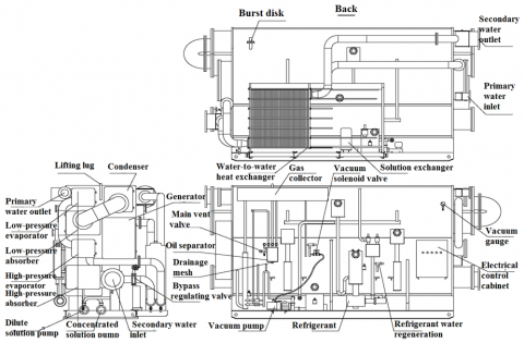
The research object is the LTDA heat pump system shown in Figure 2. This system mainly consists of an evaporator, a condenser, a generator, an absorber, a solution heat exchanger, and a temperature-driven heat exchanger.
The primary side water goes through the generator's tube side for the first cooling, the evaporator's tube side for the second cooling, and the temperature-driven heat exchanger when the LTDA heat pump system is activated. The secondary side water passes through the absorber's tube side, the condenser's tube side, and, when the LTDA heat pump system is partially activated, some of the secondary return water directly goes through the temperature-driven heat exchanger to exchange heat with the primary water that has been cooled once by the generator. Afterward, it mixes with the secondary water coming out of the condenser from the absorption unit, together providing heat to the thermal users.
In the generator, the lithium bromide solution exists in the shell side at a lower concentration, absorbing heat from the primary water cooling, evaporating into a higher temperature concentrated lithium bromide solution and superheated water vapor. After cooling in the solution heat exchanger, it enters the absorber. In the absorber, the concentrated lithium bromide solution combines with the saturated water vapor produced by the evaporator, diluting into a dilute lithium bromide solution and releasing heat during the dilution process. The tube side heats the secondary water. The dilute lithium bromide solution, after exchanging heat with the concentrated solution through the solution heat exchanger, enters the generator, completing a single cycle of the absorbent. The superheated water vapor produced in the generator enters the condenser, where it condenses into a saturated water solution and releases heat. The produced saturated water solution, after throttling, enters the evaporator. In the low-temperature, low-pressure evaporator, the unsaturated water vapor absorbs heat from the primary water's second cooling, producing saturated water vapor that enters the absorber to dilute the shell side's concentrated lithium bromide solution, releasing heat and heating the secondary water for the first time [9, 10].
Figure 2. Diagram of an LTDA heat pump system for heat exchange stations
Figure 3. Simplified process flow diagram of the LTDA heat pump system
2.2 Mathematical model
2.2.1 Model assumptions
The process flow of the LTDA heat pump system is simplified as shown in Figure 3.
The state points in the diagram are described as follows in Table 1.
The following assumptions are made to establish the model:
(1) Ignore heat transfer losses between the unit and the external environment.
(2) The entire system is in a steady flow state, and each component meets the condition of energy balance.
(3) The refrigerant liquid water is always in a saturated state.
(4) The lithium bromide solution leaving the absorber and generator is a saturated solution.
(5) Ignore thermal resistance, thermal losses, and pressure losses.
(6) Ignore the energy consumption of various pumps.
Table 1. Description of state points in the simplified process flow diagram of the LTDA heat pump system
|
State Point |
Description |
|
Point 1 |
Saturated liquid of the working substance under evaporating pressure |
|
Point 2 |
Dilute solution exiting the absorber |
|
Point 3 |
Saturated liquid of the working substance under condensing pressure |
|
Point 4 |
Concentrated solution exiting the generator |
|
Point 5 |
Concentrated solution at the start of the generation process |
|
Point 6 |
Dilute solution at the start of the absorption process |
|
Point 1’ |
Saturated water vapor corresponding to the absorber pressure |
|
Point 4’ |
Water vapor produced at the end of the generation process |
2.2.2 Model establishment
Since the absorption unit accounts for 70% of the heat load, the temperature corresponding to 70% of the heat load is determined as the critical temperature for the operation of the lithium bromide absorption heat exchanger unit alone.
Mathematical models are established based on the different characteristics of the system's heating process.
Heat load calculation of equipment:
(1) Heat absorbed by the evaporator $Q_e$:
$Q_e=D\left(h_1^{\prime}-h_3\right)$ (1)
(2) Heat absorbed by the condenser $Q_c$:
$Q_c=D\left(h_4^{\prime}-h_3\right)$ (2)
(3) Heat released by the evaporator $Q_a$:
$\begin{aligned} Q_a & =\left(M_L-M_H\right) h_1^{\prime}+M_H \cdot h_6-M_L \cdot h_2^{\prime} \\ & =D\left[h_1^{\prime}-(a-1) h_6-a \cdot h_2\right]\end{aligned}$ (3)
(4) Heat released by the generator $Q_g$:
$\begin{aligned} Q_g & =\left(M_L-M_H\right) h_4^{\prime}+M_H \cdot h_4-M_L \cdot h_5 \\ & =D\left[h_4^{\prime}+(a-1) h_4-a h_5\right]\end{aligned}$ (4)
The actual circulating flow rate of the heat pump working substance:
$D=\frac{Q}{\frac{Q_a+Q_c}{D}}=M_L-M_H$ (5)
$a=\frac{X_H}{X_H-X_L}$ (6)
The heat exchange efficiency η:
$\eta=\frac{Q_a+Q_c}{Q_g}$ (7)
These calculations assume energy balance across the system, ignoring energy losses in various parts, and focus on the transfer of heat from the primary side through changes in lithium bromide solution concentration and phase changes of water to the secondary side. This includes heat changes in the generator, absorber, condenser, evaporator, and temperature heat exchanger. The heat exchange efficiency serves as the evaluation criterion. A program was developed in Matlab to solve the mathematical model.
3.1 Project overview
The experimental study focuses on a LTDA heat pump system in a heat exchange station responsible for a heating area of 47,000 square meters, with radiators at the heating ends. The system, with a heating capacity of 2500kW, can handle up to 70% of the heat load at the design outdoor temperature through the absorption unit, with the temperature-driven heat exchanger handling up to 30% of the load.
3.2 Experimental content and purpose
The study investigates the operational modes of the LTDA heat pump system used in heat exchange stations. It examines mass adjustment, volume adjustment, and mass-volume adjustment when only the absorption unit is activated, based on ambient temperature. When the entire system is activated, it varies the flow rate ratio entering the temperature-driven heat exchanger and secondary return water according to outdoor temperature changes. Data was collected, organized, and analyzed to validate and analyze the established system model, assessing its accuracy and applicability. The experimental scheme aims to improve system efficiency while ensuring heating supply, considering changes in external temperature and load.
During the experiments, flow and temperature were adjusted using valve openings. Ultrasonic flow meters and thermometers were used to measure primary and secondary side supply and return water temperatures and flows, as well as flows entering the unit and temperature-driven heat exchanger. Experimental data was recorded, processed, and analyzed in detail.
3.3 Experimental instruments
The selection criteria for temperature and flow measurement instruments and meters include accuracy in measuring the required parameters, suitability for the experimental site and climate, and compliance with the principles and accuracy requirements of the testing method. The parameters for the remote transmission thermometers used in the experiment are as follows (Table 2):
Table 2. Parameters of remote transmission thermometer
|
Measuring Range (℃) |
Relative Humidity (%) |
Indication Accuracy |
Ambient Temperature (℃) |
Probe Shock Resistance (MPa) |
Probe Diameter (mm) |
|
-40~600 |
5~95 |
1.5 |
-10~55 |
6 |
8~10 |
Parameters of the electromagnetic flowmeter are shown in Table 3.
Table 3. Parameters of electromagnetic flowmeter
|
Fluid Temperature (℃) |
Rated Pressure (MPa) |
Conductivity (μs/m) |
Ambient Temperature (℃) |
Electrical Interface |
|
-40~250 |
1.6 |
5 |
-35~60 |
M20*1.5 |
3.4 Experimental method
Based on the actual project overview, the unit can provide up to 70% of the maximum heat load. In severe cold regions, the outdoor temperature during the heating season ranges from -13.6℃ to 5℃. Thus, the temperature range for operating only the lithium bromide absorption heating unit is set from -4℃ to 5℃ for research; the temperature-driven heat exchanger provides up to 30% of the heat load, with its operational temperature range determined to be from -13.6℃ to -4℃.
When only the lithium bromide absorption heating unit is used, i.e., when the heat load ratio is 0.4-0.7, at a certain outdoor temperature, parameters such as the primary and secondary side flow and temperature under different adjustment methods were recorded. When the entire LTDA heat pump heating system is in use, i.e., when the heat load ratio is 0.7-1, the flow ratio of secondary return water entering the temperature-driven heat exchanger and secondary return water is adjusted under different temperatures. The temperatures and flows of the primary supply and return water, secondary water entering the unit and temperature-driven heat exchanger, secondary water temperature exiting the temperature-driven heat exchanger and unit, and the supply water temperature on the user side were recorded.
3.5 Experimental conditions and data processing
(1) During the experiment, required parameters such as primary and secondary side supply and return water temperatures under all experimental scheme conditions were recorded.
(2) After changing the operation mode, the first data recording was done 5 minutes after the system showed stable data, with three recordings for each adjustment method, totaling 15 minutes.
(3) All recorded data for each adjustment method was orderly filled into the experimental record sheet, and was processed by calculating the arithmetic mean.
(4) All outliers in the test process were excluded.
When only the LTDA heat pump unit was activated, i.e., when the heat load ratio was 0.4-0.7, multiple experiments were conducted. The temperatures and flows of the primary supply and return water, as well as the secondary supply and return water temperatures and flows under three different adjustment methods (mass adjustment, volume adjustment, and mass-volume adjustment), were measured at environmental temperatures of -4℃, -1℃, 2℃, and 5℃.
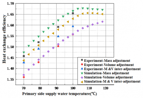
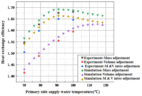
Data collected under different environmental temperatures was organized for comparison between simulation data and experimental data, as shown in Figures 4 to 7, to verify the reliability of the model and program.
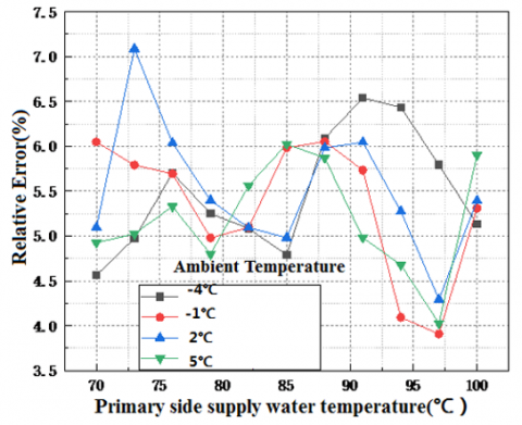
Figure 4. Experimental verification of heat exchange efficiency at -4°C under different adjustment methods
Figure 5. Experimental verification of heat exchange efficiency at -1°C under different adjustment methods
Figure 6. Experimental verification of heat exchange efficiency at 2°C under different adjustment methods
Figure 7. Experimental verification of heat exchange efficiency at 5°C under different adjustment methods
The experimental verification of heat exchange efficiency at various outdoor temperatures and under different adjustment methods demonstrates a consistent trend in heat exchange efficiency changes across mass adjustment, volume adjustment, and mass-volume adjustment strategies. This consistency was observed in the operational range of primary side supply water temperatures between 70°C and 100°C. When examining the heating unit alone and disregarding heat transport losses, the system exhibits higher heat exchange efficiency under mass adjustment and mass-volume inter-adjustment strategies, with lower efficiency under volume adjustment. This aligns with practical observations.
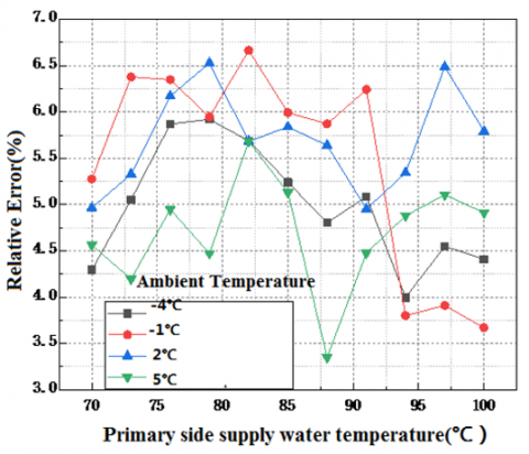
The average of multiple experimental data under the same conditions is processed as the true experimental value. Across different conditions, absolute error reflects the deviation of measured values from true values.
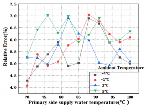
Figure 8. Relative error during secondary side mass adjustment
Under various conditions, the relative error between true values and experimental values, as shown in Figures 8 to 10, is defined as the ratio of absolute error to measured values, representing the percentage of absolute error in relation to the true value. Analysis of the graphs reveals that for the absorption unit operating process, the relative error in heat exchange efficiency ranges from 3.3% to 7.05% under mass adjustment conditions; the relative error under volume adjustment conditions ranges from 3.9% to 7.08%; and the relative error in energy efficiency under mass-volume inter-adjustment conditions ranges from 4.2% to 7.02%.
Figure 9. Relative error during secondary side volume adjustment
Figure 10. Relative error during secondary side mass-volume inter-adjustment
In summary, the relative error ranges between 3.30% and 7.08%, not exceeding 10%, which proves the reliability of the mathematical model and validates the correctness of the Matlab program, providing support for the model and software for subsequent research.
The simulation study involves implementing mass adjustment with phased flow changes on the primary side using the lithium bromide absorption heating unit, as well as mass adjustment, volume adjustment, and mass-volume adjustment on the secondary side. When activating the LTDA heat pump heating system, mass adjustment was applied to the primary side, with changes to the ratio of flow entering the temperature-driven heat exchanger and secondary return water. Using heat exchange efficiency as the evaluation criterion, the aim is to identify the most effective operational adjustment methods for the LTDA heat pump system in heat exchange stations across different heat load ratio stages.
6.1 Simulation study of adjustments when using the lithium bromide absorption heating unit
Based on the design of the actual engineering system where the absorption unit is responsible for up to 70% of the maximum heat load, the optimal operational mode of the unit was analyzed for a heat load ratio of 0.4-0.7.
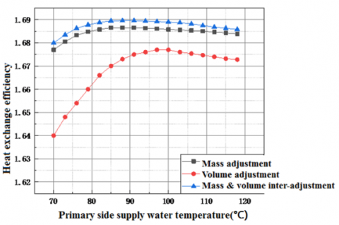
As illustrated in Figures 11 to 14, taking the average operational conditions, the optimal primary side supply water temperature ranges from 83°C to 86°C with a heat load ratio of 0.40-0.41, and the secondary side adjustment method is mass-volume inter-adjustment, achieving the highest heat exchange efficiency of 1.69. For a heat load ratio of 0.41-0.44, the optimal primary side supply water temperature ranges from 86°C to 90°C with mass-volume inter-adjustment on the secondary side, reaching a heat exchange efficiency of 1.691. With a heat load ratio of 0.44-0.47, the optimal primary side supply water temperature ranges from 90°C to 93°C with mass adjustment, achieving a heat exchange efficiency of 1.685. Lastly, for a heat load ratio of 0.47-0.51, the optimal primary side supply water temperature ranges from 93°C to 95°C with mass adjustment on the secondary side, reaching the highest heat exchange efficiency of 1.68.
Figure 11. Heat exchange efficiency of the unit at a heat load ratio of 0.40-0.41
Figure 12. Heat exchange efficiency of the unit at a heat load ratio of 0.41-0.44
Figure 13. Heat exchange efficiency of the unit at a heat load ratio of 0.44-0.47
Figure 14. Heat exchange efficiency of the unit at a heat load ratio of 0.47-0.51
Figure 15. Heat exchange efficiency of the unit at a heat load ratio of 0.51-0.54
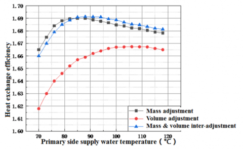
As shown in Figures 15 to 17, considering actual conditions and their average temperatures, with a primary side supply water flow rate ratio of 80%, and a heat load ratio of 0.51-0.54, the optimal primary side supply water temperature ranges from 79°C to 85°C, with the secondary side adjustment method being mass-volume inter-adjustment, achieving the highest heat exchange efficiency of 1.694. For a heat load ratio of 0.54-0.57, the optimal primary side supply water temperature ranges from 85°C to 90°C, with mass adjustment on the secondary side, resulting in the highest heat exchange efficiency of 1.685. For a heat load ratio of 0.57-0.6, the optimal primary side supply water temperature ranges from 90°C to 94°C, with mass adjustment on the secondary side, leading to the highest heat exchange efficiency of 1.72.
Figure 16. Heat exchange efficiency of the unit at a heat load ratio of 0.54-0.57
Figure 17. Heat exchange efficiency of the unit at a heat load ratio of 0.57-0.60
Figure 18. Heat exchange efficiency of the unit at a heat load ratio of 0.60-0.63
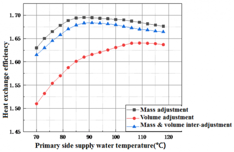
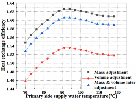
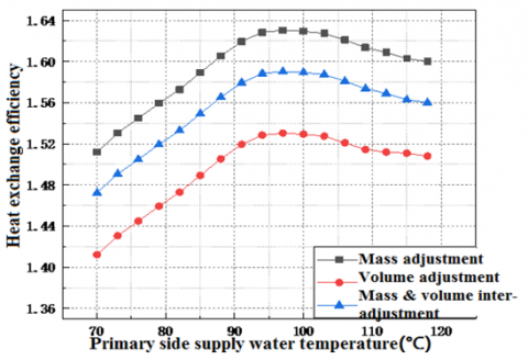
As illustrated in Figures 18 to 20, taking into account actual conditions and their average temperatures, with a primary side supply water flow rate ratio of 100%, and a heat load ratio of 0.60-0.63, the optimal primary side supply water temperature ranges from 80°C to 85°C, with mass adjustment on the secondary side, achieving the highest heat exchange efficiency of 1.618. For a heat load ratio of 0.63-0.66, the optimal primary side supply water temperature ranges from 85°C to 90°C, with mass adjustment on the secondary side, resulting in the highest heat exchange efficiency of 1.628. For a heat load ratio of 0.66-0.7, the optimal primary side supply water temperature ranges from 90°C to 96°C, with mass adjustment on the secondary side, leading to the highest heat exchange efficiency of 1.63.
Figure 19. Heat exchange efficiency of the unit at a heat load ratio of 0.63-0.66
Figure 20. Heat exchange efficiency of the unit at a heat load ratio of 0.66-0.70
In summary, at a heat load ratio of 0.4-0.7, under the operational state of only activating the lithium bromide absorption unit, using heat exchange efficiency as the standard, the efficiency of volume adjustment on the secondary side is significantly lower than that of mass adjustment and mass-volume inter-adjustment when the primary side changes the flow rate in phases. The optimal primary side supply water temperatures and the adjustment methods on the unit's secondary side are as shown in Table 4.
6.2 Simulation study of adjustments when using the LTDA heat pump system
For heat load ratios from 0.70 to 1.00, where the heating demand exceeds 70% of the maximum heat load, the absorption unit alone cannot meet the required heating demand. Thus, it's necessary to activate the temperature-driven heat exchanger alongside the unit to provide heat. The ratio of the flow entering the temperature-driven heat exchanger to the actual secondary side flow is defined as the secondary side temperature-driven heat exchanger flow rate ratio. The ratio of the heating capacity provided by the absorption unit to that of the temperature-driven heat exchanger is referred to as the system heat exchange ratio.
Table 4. Operating adjustment methods for the lithium bromide absorption heat exchanger unit
|
Heat Load Ratio |
Primary Side Flow Rate |
Primary Side Supply Water Temperature (℃) |
Secondary Side Adjustment Method |
|
0.40-0.41 |
60% |
83-86 |
Mass-Volume Inter-adjustment |
|
0.41-0.44 |
86-90 |
Mass-Volume Inter-adjustment |
|
|
0.44-0.47 |
90-93 |
Mass Adjustment |
|
|
0.47-0.51 |
93-95 |
Mass Adjustment |
|
|
0.51-0.54 |
80% |
79-85 |
Mass-Volume Inter-adjustment |
|
0.54-0.57 |
85-90 |
Mass Adjustment |
|
|
0.57-0.60 |
90-94 |
Mass Adjustment |
|
|
0.60-0.63 |
100% |
80-85 |
Mass Adjustment |
|
0.63-0.66 |
85-90 |
Mass Adjustment |
|
|
0.66-0.70 |
90-96 |
Mass Adjustment |
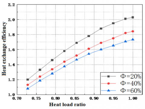
As shown in Figures 21 to 23, the heat exchange efficiency curve follows a parabolic trend under conditions of constant secondary side temperature-driven heat exchanger flow rate ratio but varying primary side supply water temperatures. The efficiency increases with the heat load ratio but the increase diminishes as the load increases. The maximum heat exchange efficiency occurs at a primary side supply water temperature of 110°C, with the lowest efficiency observed at 100°C.
Figure 21. Heat exchange efficiency when Φ=20%
Figure 22. Heat exchange efficiency when Φ=40%
Figure 23. Heat exchange efficiency when Φ=60%
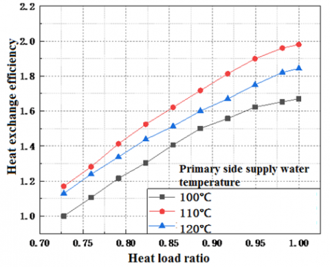
Figure 24. Heat exchange efficiency when primary side supply water temperature is 100℃
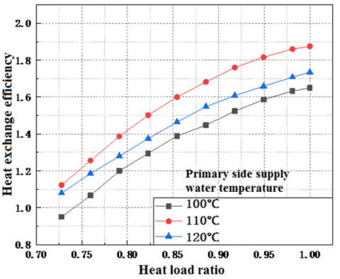
Figures 24 to 26 indicate that the heat exchange efficiency curve also follows a parabolic trend under conditions of constant primary side supply water temperature but varying secondary side temperature-driven heat exchanger flow rate ratios. Heat exchange efficiency is directly proportional to the heat load ratio, but the magnitude of efficiency change decreases as the heat load ratio increases. With heat exchange efficiency as the evaluation criterion, the optimal secondary side temperature-driven heat exchanger flow rate ratio for activating the LTDA heat pump heating system is 20%.
Figure 25. Heat exchange efficiency when primary side supply water temperature is 110℃
Figure 26. Heat exchange efficiency when primary side supply water temperature is 120℃
In summary, when activating the LTDA heat pump heating system with the primary side flow at rated capacity, primary side supply water temperature at 110°C, and a secondary side temperature-driven heat exchanger flow to actual flow ratio of 20%, the system achieves a high heat exchange efficiency of 2.18.
Addressing the challenges faced by LTDA heat pump systems in heat exchange stations within engineering applications, this study, integrated with a residential heating project, explores changes in operational adjustments during the winter heating season. Taking the LTDA heat pump system for heat exchange stations as the subject, and energy efficiency as the evaluation criterion, a mathematical model of the unit was developed through experimental research and data simulation. The model was analyzed using Matlab software to simulate the adjustment methods on both the primary and secondary sides of the system, identifying the optimal operational conditions under different adjustment methods. The conclusions are as follows:
(1) The LTDA heat pump system, consisting of an absorption unit and a temperature-driven heat exchanger, was designed to handle the maximum heat load. The heat load ratio for operating solely the absorption unit during the heating season was calculated to be between 0.4-0.7, with the combined operation of the unit and temperature-driven heat exchanger covering a heat load ratio of 0.7-1.0.
(2) When only activating the lithium bromide absorption heat exchanger unit during the heating season, with a heat load ratio of 0.4-0.7, mass adjustment with phased flow changes is applied to the primary side. Simulations are conducted with primary side supply water temperatures ranging from 70°C to 100°C, in 2°C temperature gradients, and adjustments on the secondary side include mass adjustment, volume adjustment, and mass-volume inter-adjustment, using system efficiency as the evaluation criterion to determine the optimal operating conditions. For a primary side flow rate ratio of 60% and a heat load ratio of 0.40-0.44, the optimal primary side supply water temperature is 86°C-90°C, with mass-volume inter-adjustment on the secondary side; for a heat load ratio of 0.44-0.51, the optimal primary side supply water temperature is 93°C-95°C, with mass adjustment on the secondary side; at a primary side supply water flow rate ratio of 80%, with a heat load ratio of 0.51-0.54, the optimal primary side supply water temperature is 85°C, with mass-volume inter-adjustment on the secondary side; for a heat load ratio of 0.54-0.60, the optimal primary side supply water temperature is 90°C-94°C, with mass adjustment on the secondary side. At a primary side supply water flow rate ratio of 100%, with a heat load ratio of 0.60-0.70, the optimal primary side supply water temperature is 85°C-96°C, with mass adjustment on the secondary side.
(3) During the heating season, when the LTDA heat pump heating system is activated, with a heat load ratio of 0.7-1.0, the concept of the heat exchange ratio is introduced. The primary side of the unit operates at rated flow, and the supply water temperatures are considered at 100°C, 110°C, and 120°C. The discussions cover the heat exchange ratios between the unit and the temperature-driven heat exchanger at secondary side temperature-driven heat exchanger flow to actual flow ratios of 20%, 40%, and 60%, along with the secondary side outlet temperatures, using heat exchange efficiency as the evaluation criterion. Analysis indicates that the optimal operational mode for the system, when activating the LTDA heat pump heating system, is achieved with a primary side supply water temperature of 110°C and a secondary side temperature-driven heat exchanger flow to actual flow ratio of 20%. Under these conditions, the system's highest heat exchange efficiency is 2.18.
Research on LTDA heat pump systems both domestically and internationally has primarily focused on their application and study in cogeneration plants, with optimization of performance and operational adjustments targeting those used in cogeneration facilities, achieving significant research outcomes [11-21]. However, studies on LTDA heat pump systems for heat exchange stations have been less frequent, with the main research still focusing on optimizing the internal structure and parameters of the units, enhancing efficiency through multi-stage efficiency methods, and conducting in-depth investigations into internal lithium bromide crystallization issues and solution flow problems within these systems for heat exchange stations. Yet, there has been a lack of systematic and in-depth research on the adjustment and operational methods of LTDA heat pump systems during the heating season when applied in heat exchange stations. This paper focuses on the LTDA heat pump system used in heat exchange stations, conducting experimental and simulation studies on the adjustment methods of the system's primary and secondary sides in phases to identify the optimal operational conditions, namely, the operating conditions that result in the maximum heat exchange efficiency.
This project is supported by the Science Research Project of the Education Department of Hebei Province (Grant No.: QN2022084).
[1] Lin, F., Li, Y., Zhang, S.G., Jiang, Y., Zhao, X.L. (2010). Concept and application of absorption heat transfer. Building Science, 10: 136-140. https://doi.org/10.3969/j.issn.1002-8528.2010.10.028
[2] Zhang, S., Fu, L., Li, Y., Lai, Z., Xiao, C. (2015). Process and equipment based on absorption heat exchange. Heating Ventilating & Air Conditioning, 45(9): 85-90.
[3] Xie, X., Jiang, Y. (2015). An ideal model of absorption heat pump with ideal solution circulation. Journal of Refrigeration, 36(1): 13-23. https://doi.org/10.3969/j.issn.0253-4339.2015.01.001
[4] Cai, H., Xie, X., Jiang, Y. (2019). Research on design method of multistage absorption heat exchanger with large temperature difference and performance measurement in late cold season. District Heating, 2019(1): 1-7+25. https://doi.org/10.16641/j.cnki.cn11-3241/tk.2019.01.001
[5] Wang, Z. (2018). Research on application of lithium bromide absorption heat pump in central heating heat exchange station. Dissertation, Harbin Institute of Technology, Heilingjiang, China.
[6] Zhu, T. (2015). Research and development and Performance experiment of single-effect lithium bromide absorption heat exchanger unit, Dissertation, Harbin Institute of Technology, Heilongjiang, China.
[7] He, Y. (2017). Research on safe operation regulation of single-effect lithium bromide absorption heat exchanger unit, Dissertation. Harbin Institute of Technology, Heilongjiang, China.
[8] Chen, Q., Wang, X. (2020). Analysis of design conditions for LiBr absorption heat pump. Building Energy & Environment, 39(3): 49-53+11.
[9] Shen, J., Su, S., Zou, T. (2001). Study on the counter series connection TC triple effect lithium bromide absorption refrigeration cycle. Journal of Engineering Thermophysics, 2001(4): 417-419. https://doi.org/10.3321/j.issn:0253-231X.2001.04.007
[10] Zhu, H., Yao, H., Li, J., Tang, L., Zhang, F., Zhao, W., Yang, Y. (2020). Aspen plus process simulation of lithium bromide absorption heat pump unit. Guangdong Chemical Industry, 47(16): 149-150. https://doi.org/10.3321/j.issn:0253-231X.2001.04.007
[11] Yue, H. (2009). Study on modeling and dynamic simulation of lithium bromide absorption heat pump. Dissertation, North China Electric Power University Beijing, China.
[12] Xiong, J., Liao, Y., Hu, X., Huang, P. (2022). Analysis of dynamic of modeling and operation characteristics of LiBr absorption heat pump. Thermal Power Engineering, 37(2): 122-128+159. https://doi.org/10.16146/j.cnki.rndlgc.2022.02.017
[13] Zhou, Z. (2014). Research and application on optimal operation of heating system with large temperature difference. Dissertation, Beijing University of Civil Engineering and Architecture, Beijing, China.
[14] Zhong, J., Sun, Y., Li, W. (2017). The application of absorption type large temperature difference heat exchanger in heating system is discussed. District Heating, 6: 123-126+134. https://doi.org/10.16641/j.cnki.cn11-3241/tk.2017.06.023
[15] Jia, M. (2002). Several main calculating equations of properties parameter of LiBr-H2O. Journal of Zhanjiang Ocean University, 3: 52-58. https://doi.org/10.3969/j.issn.1673-9159.2002.03.011
[16] Grossman, G., Zaltash, A., Abusamra, H. (2001). ABSIM-modular simulation of advanced absorption systems. International Journal of Refrigeration, 24: 531-543. https://doi.org/10.1016/S0140-7007(00)00051-7
[17] Jeong, S. (1998). Dynamic simulation of an absorption heat pump for recovering low grade waste heat. Applied Thermal Engineering, 18(1-2): 4-12. https://doi.org/10.1016/S1359-4311(97)00040-9
[18] Ahmadi, P., Rosen, M.A., Dincer, I. (2012). Multi-objective exergy-based optimization of a polygeneration energy system using an evolutionary algorithm. Energy, 46(1): 21-31. https://doi.org/10.1016/j.energy.2012.02.005
[19] Ahmadi, P., Dincer, I., Rosen, M.A. (2014). Thermoeconomic multi-objective optimization of a novel biomass-based integrated energy system. Energy, 68: 958-970. https://doi.org/10.1016/j.energy.2014.01.085
[20] Bulgan, A.T. (1995). Optimization of the thermodynamic model of aqua-ammonia absorption refrigeration systems. Energy Conversion and Management, 36(2): 135-143. https://doi.org/10.1016/0196-8904(94)00028-X
[21] Yang, B., Jiang, Y., Fu, L., Zhang, S. (2018). Modular simulation of cogeneration system based on absorption heat exchange (Co-ah). Energy, 153: 369-386. https://doi.org/10.1016/j.energy.2018.04.063