Sulistyo*![]() | Mohamad Said Kartono Tony Suryo Utomo
| Mohamad Said Kartono Tony Suryo Utomo![]() | Reza Abdu Rahman
| Reza Abdu Rahman![]()
© 2023 IIETA. This article is published by IIETA and is licensed under the CC BY 4.0 license (http://creativecommons.org/licenses/by/4.0/).
OPEN ACCESS
The efficacy of a latent thermal battery (LTB) system is significantly enhanced through the implementation of a multistage configuration. This study is centered on the utilization of organic phase change material (OPCM) as the storage medium within the LTB, aimed at augmenting the charge and discharge rates of the system. The adoption of a multistage approach effectively mitigates the impact of partial phase transitions within the OPCM, facilitating a higher cumulative charging rate of 2.39℃/min. This arrangement is instrumental in minimizing the instability of heat release from each tank, thereby ensuring a consistent heating process for the working fluid throughout the discharge cycle. Consequently, the multistage LTB demonstrates an elevated power rate, reaching up to 7.64 Watts, with a sustained power duration of 45.5 minutes. Such performance signifies an efficacious heat discharge mechanism, substantially improving the overall functionality of the LTB system. The proposed multistage LTB configuration is particularly advantageous for thermal systems operating at low temperatures, including solar water and air heaters. Additionally, the enhanced charge and discharge rates contribute to an increased effective energy density of the LTB, aligning with the objectives of developing compact and efficient energy storage systems. The findings of this research underscore the potential of multistage LTB systems in maximizing operational efficiency in thermal energy storage, thereby contributing to the advancement of sustainable energy solutions.
energy, heat, phase change material, storage, thermal
Energy storage technology (EST), a pivotal element in renewable energy systems, has seen a significant evolution over the past decade, particularly in the widespread adoption of wind and solar energy facilities. This growth is attributed to advancements in EST, as documented in recent studies [1-3]. EST encompasses a range of storage solutions, including both electric and thermal batteries. Electric batteries are predominantly utilized in systems focused on generating electricity from renewable sources. Conversely, thermal batteries find application in renewable thermal systems and are increasingly recognized for their role in industrial processes, particularly in harnessing waste heat. This application enhances the thermal efficiency of systems and contributes to an increase in net positive energy output, demonstrating the versatility and broad applicability of thermal batteries in various thermal systems [4].
Thermal batteries are categorized into three primary types based on the storage material used. The first type, the sensible system, leverages the sensible properties of the storage material and has already achieved commercialization. However, it is constrained by low energy density, limiting its feasibility for large-scale and mobile applications [5]. The second type, the thermochemical system, is characterized by minimal thermal losses and is thus suited for long-term operations. Despite its potential, the thermochemical system remains primarily in the experimental phase due to operational complexities [6]. The most promising among these is the LTB, which utilizes phase change material (PCM). LTBs offer a higher energy density and can integrate the sensible properties of the storage material, enhancing their applicability. This combination positions LTBs favorably in terms of technology readiness, making them suitable for a variety of thermal systems, including space heating and water heaters [7, 8].
PCM, particularly effective in low-temperature LTB ranging from 50-100°C, has garnered significant interest [9]. These OPCMs are favored for their high heat of fusion and cost-effective storage properties. However, a primary limitation is their slow thermal response, primarily due to low thermal conductivity. Various enhancement methods have been explored, such as incorporating high-metal content volcanic ash [10], amalgamating with polymers [11], and adding nano-additives to the working fluid [12]. Nevertheless, these methods encounter a significant challenge: a decrease in storage capacity, attributed to the incorporation of solid additives and binders in the composite. An alternative strategy involves modifications to the storage tank design. This has been achieved through the utilization of metal foam [13], coil heat exchangers [14], and copper wire mesh [15], which generally improve the average thermal response of the LTB during operation. However, this approach is not without drawbacks, as the increased surface area of the heat exchanger within the storage tank can lead to a reduction in the system's effective volumetric capacity.
Another avenue for enhancing LTB performance is through the microencapsulation of the storage material [16]. Additionally, incorporating a bypass line for the working fluid has proven to be a viable method, effectively reducing total melting time by up to 67% and thus enhancing system charging efficiency [17]. Adjustments to the piping arrangement within the storage tank also influence LTB operation, particularly in accelerating the PCM melting process by approximately 18.2% during the charging process [18]. Common solutions often involve modifying the operation of the working fluid and the dimensions of the storage tank. Despite these efforts, further advancements are required to optimize the operational efficiency of LTB units.
Improving the operational efficiency of an LTB unit typically focuses on utilizing a single storage tank. However, this approach is constrained by a low-temperature gradient [19], particularly evident in active LTB systems employing liquid as the working fluid, thereby limiting overall performance [20]. Research by Mao et al. [21] on single tank LTB for water heating applications revealed a maximum heat release of only 13.8% when the working fluid's inlet temperature dropped to 4℃. To address this limitation, Abtahi Mehrjardi et al. [22] proposed the use of auxiliary fluid, which increased the energy storage rate to 0.341 kW/kg. Furthermore, Shalaby et al. [23] transformed the storage tank into a direct heat exchanger unit, achieving a daily efficiency of approximately 65%. Despite these advancements, these modifications still relied on a single storage tank, facing inherent limitations, especially in terms of effective storage capacity.
A potential solution to overcome these limitations involves integrating multiple storage tanks into a single system, enhancing both storage capacity and operational efficiency [24]. For instance, the multistage hydrogen refueling system has demonstrated reduced specific energy consumption for hydrogen refueling, thereby boosting the system's net positive energy [25]. Similarly, cascaded molten salt technology has shown promise in augmenting the storage capacity of high-temperature thermal storage tanks [26]. Consequently, a multistage LTB, particularly one that utilizes organic phase change material (OPCM), emerges as a promising strategy to enhance the thermal operation of low-temperature Thermal Energy Storage (TES) systems. However, a comprehensive evaluation of the characteristics of a multistage LTB utilizing OPCM is requisite.
The current study is directed towards assessing the performance and operational characteristics of a three-stage LTB unit employing OPCM. This involves an evaluation of the charging characteristics and power profile, aimed at elucidating the efficacy of the multistage OPCM-LTB concept. It is anticipated that the outcomes of this study will contribute to the enhancement of the effective storage capacity of LTB systems. Moreover, the proposed methodology can be integrated with recent advancements in storage materials and heat transfer enhancements within the storage tank. Hence, the findings of this study are anticipated to be pivotal in advancing the development of LTB systems for energy storage applications.
Figure 1(a) shows the arrangement of the proposed multistage LTB, which operated in active mode. The active mode involves working fluid as the heating/cooling medium to provide convective heat transfer within the system [27]. Three storage tank was arranged in series connection relative to the working fluid flow direction. The fluid enters the LTB from tank A. The heat transfer process was done using working fluid AT-400 with the detailed thermophysical properties can be found here [28]. During the charge cycle, the working fluid was heated by two consecutive electric heaters employed as a heat source. The heat source was designed to maintain the outlet temperature of working fluid around 150℃. The charge cycle was stopped once the PCM's temperature reached 100℃. After that, the discharge cycle was performed. In this stage, two recirculating oil chiller was used as heat sink to maintain the temperature of working fluid at 25℃. The discharge cycle was stopped once the PCM's temperature reached 40℃.
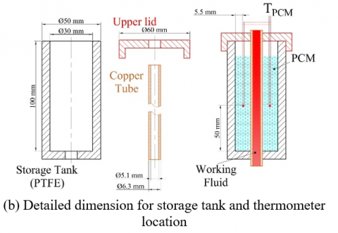
Figure 1. Multistage arrangement for experiment test and dimension of the storage tank
Figure 1(b) presents the detailed dimensions of the storage tank and thermometer position. The performance of multistage LTB from the heating and cooling test was analyzed using the temperature as the working indicator [29]. Thus, several thermometers were installed to measure the temperature of the PCM within the tank. The heat releasement characteristics and power indicators can be analyzed by evaluating the temperature of the working fluid during the cooling test. Therefore, two thermometers were used to measure the working fluid's inlet (TA) and outlet (TB) temperature. The measurement was taken using K-type thermocouples with an absolute error ± 0.2℃.
The PCM was located within the storage tank. The tank was made of polytetrafluoroethylene (PTFE) with a melting temperature of around 300℃, suitable for the desired working temperature of the multistage LTB. The mass of the PCM within each tank was 54 grams. The OPCM for each storage tank were tetradecanoic acid (tank A), hydrocarbon wax (tank B) and octadecanoic acid (tank C). The thermal capacity of each storage material was assessed through the calorimetry method (DSC method with a scanning rate of 10 K/min). The same method was also used for evaluating the melting and solidification temperature of the storage material.
The heating profile for each storage tank is presented in Figure 2. It shows that all PCM demonstrates non-plateau lines during solid-liquid transition. It is affected by the unstable phase transition, which makes the solid-liquid transition followed by temperature increment [30]. The heating process is started by solid-sensible region, which is done after 3.5 minutes for hydrocarbon wax (HW), 4 minutes for tetradecanoic acid (TA) and 6 minutes for octadecanoic acid (OA). The TA is located in the first tank but shows a slower charging rate in the solid-sensible region than HW. It is affected by the low heat transfer rate for TA, which requires further adjustment to improve its heat transfer rate [31].
The longest duration for phase transition is obtained by HW which is located in tank B. The average charging rate for HW during phase transition is only 0.47℃/min, much lower than TA (0.87℃/min) and OA (1.02℃/min). OA obtains the highest temperature increment during phase transition with a temperature gradient of 16.3℃. As a result, OA has the lowest charging rate compared to the other tanks. The average charging rate for OA is only 2.13℃/min. It is affected by the location of OA in the last arrangement since the energy of the working fluid is absorbed notably in tank A and tank B. Thus, it has the lowest temperature when entering tank C.
Figure 2. Temperature increment of each PCM in the multistage LTB
Figure 3. Thermal properties for each PCM within the multistage LTB
Each tank's charge characteristic is also related to the thermal capacity for each PCM within the tank. For example, the lowest charging rate is obtained by OA. As seen in Figure 3, OA has the highest heat of fusion compared to TA and HW. Locating the OA in the last arrangement is advantageous since the residual heat from the working fluid can be absorbed effectively, increasing the energy ratio during the charging process. HW obtains the highest deviation between melting and freezing temperatures with a supercooling degree of around 9.3℃. It makes the heat transfer rate during phase transition ineffective [32], which explains the lowest charging rate for HW compared to OA and TA. TA has the lowest melting temperature, initiating an early phase transition process during the charging process (Figure 2).
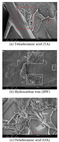
The surface profile for each PCM within the storage tank is displayed in Figure 4. It helps to explain the change in charging rate for each OPCM during the heating stage. The carboxyl profile for fatty acid (TA and OA) is observed distinctively compared to the hydrocarbon profile for HW. The fatty acids show a tiny hole (red circle in Figure 4(a) and Figure 4(c)), which is affected by the presence of oxygen in their chemical formula [33]. Local agglomeration is found for TA (red square in Figure 4(a)), while a fragmented surface is found for OA (white circle in Figure 4(c)). In contrast, the corrugated profile for HW is notable due to the slow freezing process during solidification (white square in Figure 4(b)). It explains the high-temperature gradient for the HW (Figure 3).
The multistage arrangement promotes a better state of charge or charge indicator level (CIL) level for each storage tank. The CIL level comes from the temperature increment of each tank during the charging process [34]. As seen in Figure 5, the cumulative charge level for solid sensible stage is 38.23%, implying that all storage tanks can be charged effectively at this stage. Thus, the effect of thermal properties for each PCM can be minimized. For example, TA reaches the final solid sensible stage with CIL 33.1% since it has the lowest melting temperature compared to paraffin (Figure 3). The low heat of fusion for paraffin that located in the second tank can be minimized by the presence of TA in the first tank, which minimizes the charge level variation. The high melting temperature and heat of fusion for OA that located in the final arrangement is advantageous to promotes a higher charge level. The CIL clearly demonstrates the key performance of multistage LTB.
Figure 4. Surface observation for the PCM
Figure 5. Charging level profile for each storage tank
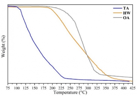
The decomposition profile for each PCM is plotted in Figure 6. Each PCM shows a direct thermal decomposition. The TA has direct decomposition from 110℃-230℃, which is much lower compared to OA, which starts to decompose between 230℃-350℃. OA has a higher molecular chain than TA, allowing it to decompose at higher temperatures. In contrast, HW has a more extended decomposition range between 190℃-395℃, which is affected by the alkane profile for HW. Despite all the variations, each PCM has a direct decomposition above 100℃, making it favorable for low-temperature applications, particularly solar water and air heaters.
Figure 6. Decomposition profile for each PCM
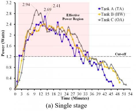
The heat is released during the discharge process, which can be drawn as a power curve according to the energy balance of the working fluid. The cut-off value for each tank is set at 1.2 Watts by considering the size of each tank. As seen in Figure 7(a), the power profile for each storage tank varies. The highest power is achieved by tank C, which uses OA as the PCM. OA has the highest melting temperature and heat of fusion (Figure 3), which delivers a higher power rate. Moreover, the tank C is located at the end of the tank arrangement, which makes the power rate can be elevated significantly. It indicates that PCM's thermal properties also play a significant role in promoting a better power rate for LTB.
Figure 7. The power profile of each tank and system
The power curve for tank B is generally steady, with the highest power of 2.41 Watts. It is affected by the slow discharge process of HW, which reduces the average heat release from the PCM to the working fluid. Contrary to that, tank A indicates a better power rate (2.69 Watts), which can be affected by its location. However, the low melting point of TA decreases the effective power duration from tank A. Moreover, the profile fluctuates notably, which is undesirable for specific applications that requires steady power rates.
The combined effect for each tank is shown in Figure 7(b). It shows the cumulative power rate as a system much higher than each tank. The effective power duration can be increased, making the LTB discharge the stored energy effectively. The steady power rate (6 Watts - 7.64 Watts) is achieved in more than 20 minutes. It shows that the LTB promotes a stable discharge process with a higher power rate. It makes the arrangement favorable for a fast response system. Moreover, the combined effect from each PCM within the storage tank can be an advantage to utilizing the organic-based PCM more effectively for low-temperature applications.
The operation and performance of multistage LTB are evaluated in this work. The finding indicates that using a multistage arrangement can improve the charging process. The partial melting process from organic PCM can be minimized by cascading the storage tank. The partial melting process is found at only 8.1℃ for HW, which is located in the middle arrangement. It promotes a higher effective charge process during the partial melting process for the LTB arrangement with the highest cumulative charge rate of 2.39℃/min. The effective power rate for the LTB improves by more than 200%, compared to power effective from a single storage tank. The thermal properties of each PCM are applicable for low-temperature operations such as solar water and air heaters, which operate below 100℃.
The proposed LTB arrangement can be applied to improve the performance of renewable thermal systems, especially for low-temperature operations such as solar water and air heaters. The LTB arrangement increases the effective charge and discharge process, which is essential for a better volumetric storage system. The proposed method can be considered a suitable approach to improve the operation characteristic of LTB in the thermal system. However, the work is limited to preliminary study and uses a small storage tank. Thus, further development can be focused on analyzing the large-scale system's cumulative energy balance, including further modification of the heat exchanger within each storage tank.
[1] Khademi, A., Darbandi, M., Schneider, G.E. (2020). Numerical study to optimize the melting process of phase change material coupled with extra fluid. AIAA Scitech 2020 Forum, 1-6. https://doi.org/10.2514/6.2020-1932
[2] Ismail, I., Rahman, R.A., Haryanto, G., Pane, E.A. (2021). The optimal pitch distance for maximizing the power ratio for Savonius turbine on inline configuration. International Journal of Renewable Energy Research, 11(2): 595-599. https://dorl.net/dor/20.1001.1.13090127.2021.11.2.10.9
[3] Favakeh, A., Khademi, A., Shafii, M.B. (2019). Experimental study of double solid phase change material in a cavity. In 7th International Conference on Energy Research and Development, ICERD 2019, pp. 24-31.
[4] Favakeh, A., Khademi, A., Shafii, M.B. (2023). Experimental investigation of the melting process of immiscible binary phase change materials. Heat Transfer Engineering, 44(2): 154-174. https://doi.org/10.1080/01457632.2022.2034085
[5] Caraballo, A., Galán-Casado, S., Caballero, Á., Serena, S. (2021). Molten salts for sensible thermal energy storage: A review and an energy performance analysis. Energies. 14(4): 1197. https://doi.org/10.3390/en14041197
[6] Alsabawi, K., Gray, E.M.A., Webb, C.J. (2019). The effect of ball-milling gas environment on the sorption kinetics of MgH2 with/without additives for hydrogen storage. International Journal of Hydrogen Energy, 44(5): 2976-2980. https://doi.org/10.1016/j.ijhydene.2018.12.026
[7] Khademi, A., Abtahi Mehrjardi, S.A., Tiari, S., Mazaheri, K., Shafii, M.B. (2022). Thermal efficiency improvement of Brayton cycle in the presence of phase change material. International Conference on Fluid Flow, Heat and Mass Transfer, Paper No. 135, 1-9. https://doi.org/10.11159/ffhmt22.135
[8] Gandhi, M., Kumar, A., Elangovan, R., Meena, C.S., Kulkarni, K.S., Kumar, A., Bhanot, G., Kapoor, N.R. (2020). A review on shape-stabilized phase change materials for latent energy storage in buildings. Sustainability (Switzerland), 12(22): 1-17. https://doi.org/10.3390/su12229481
[9] Brahma, B., Shukla, A.K., Baruah, D.C. (2023). Design and performance analysis of solar air heater with phase change materials. Journal of Energy Storage, 61: 106809. https://doi.org/10.1016/j.est.2023.106809
[10] Suyitno, B.M., Rahmalina, D., Rahman, R.A. (2023). Increasing the charge / discharge rate for phase-change materials by forming hybrid composite paraffin / ash for an effective thermal energy storage system. AIMS Material Science, 10(1): 70-85. https://doi.org/10.3934/matersci.2023005
[11] Suyitno, B.M., Pane, E.A., Rahmalina, D., Rahman, R.A. (2023). Improving the operation and thermal response of multiphase coexistence latent storage system using stabilized organic phase change material. Results in Engineering, 18: 101210. https://doi.org/10.1016/j.rineng.2023.101210
[12] Hosseininaveh, H., Rahgozar Abadi, I., Mohammadi, O., Khademi, A., Behshad Shafii, M. (2022). The impact of employing carbon nanotube and Fe3O4 nanoparticles along with intermediate boiling fluid to improve the discharge rate of phase change material. Applied Thermal Engineering. 215: 119032. https://doi.org/10.1016/j.applthermaleng.2022.119032
[13] Veismoradi, A., Ghalambaz, M., Shirivand, H., Hajjar, A., Mohamad, A., Sheremet, M., Chamkha, A., Younis, O. (2021). Study of paraffin-based composite-phase change materials for a shell and tube energy storage system: A mesh adaptation approach. Applied Thermal Engineering. 190: 116793. https://doi.org/10.1016/j.applthermaleng.2021.116793
[14] Ode, L., Firman, M., Rahmalina, D., Rahman, R.A. (2023). Hybrid energy-temperature method (HETM): A low-cost apparatus and reliable method for estimating the thermal capacity of solid – liquid phase change material for heat storage system. HardwareX. 16: e00496. https://doi.org/10.1016/j.ohx.2023.e00496
[15] Ebadi, S., Tasnim, S.H., Aliabadi, A.A., Mahmud, S. (2020). An experimental investigation of the charging process of thermal energy storage system filled with PCM and metal wire mesh. Applied Thermal Engineering, 174: 115266. https://doi.org/10.1016/j.applthermaleng.2020.115266
[16] Xu, Q., Zhu, L., Pei, Y., Yang, C., Yang, D., Liu, Z., Guan, B., Qiang, Y., Yang, H., Zang, Y., Ding, Y. (2023). Heat transfer enhancement performance of microencapsulated phase change materials latent functional thermal fluid in solid/liquid phase transition regions. International Journal of Heat and Mass Transfer, 214: 124461. https://doi.org/10.1016/j.ijheatmasstransfer.2023.124461
[17] Baghaei Oskouei, S., Bayer, Ö. (2023). Effect of bypassing the heat transfer fluid on charging in a latent thermal energy storage unit. Journal of Energy Storage, 62: 106959. https://doi.org/10.1016/j.est.2023.106959
[18] Olimat, A.N., Ismail, M., Abu Shaban, N., Al-Salaymeh, A. (2022). The effectiveness of the heat transfer fluid pipe orientation angle inside a latent heat thermal energy storage system. Case Studies in Thermal Engineering, 36: 102174. https://doi.org/10.1016/j.csite.2022.102174
[19] Elfeky, K.E., Mohammed, A.G., Wang, Q. (2021). Cycle cut-off criterion effect on the performance of cascaded, sensible, combined sensible-latent heat storage tank for concentrating solar power plants. Energy, 230: 120771. https://doi.org/10.1016/j.energy.2021.120771
[20] Bijarniya, J.P., Sudhakar, K., Baredar, P. (2016). Concentrated solar power technology in India: A review. Renewable and Sustainable Energy Reviews, 63: 593-603. https://doi.org/10.1016/j.rser.2016.05.064
[21] Mao, Q., Li, Y., Chen, M. (2021). Design and investigation of single tank phase change thermal storage domestic hot water system. Case Studies in Thermal Engineering, 25: 100903. https://doi.org/10.1016/j.csite.2021.100903
[22] Abtahi Mehrjardi, S.A., Khademi, A., Said, Z., Ushak, S., Chamkha, A.J. (2023). Enhancing latent heat storage systems: The impact of PCM volumetric ratios on energy storage rates with auxiliary fluid assistance. Energy Nexus, 11: 100227. https://doi.org/10.1016/j.nexus.2023.100227
[23] Shalaby, S.M., Kabeel, A.E., Moharram, B.M., Fleafl, A.H. (2020). Experimental study of the solar water heater integrated with shell and finned tube latent heat storage system. Journal of Energy Storage, 31: 101628. https://doi.org/10.1016/j.est.2020.101628
[24] Suyitno, B.M., Ismail, I., Rahman, R.A. (2023). Improving the performance of a small-scale cascade latent heat storage system by using gradual melting temperature storage tank. Case Studies in Thermal Engineering, 45: 103034. https://doi.org/10.1016/j.csite.2023.103034
[25] Yu, Y., Lu, C., Ye, S., Hua, Z., Gu, C. (2022). Optimization on volume ratio of three-stage cascade storage system in hydrogen refueling stations. International Journal of Hydrogen Energy, 47(27): 13430-13441. https://doi.org/10.1016/j.ijhydene.2022.02.086
[26] Mao, Q., Zhang, Y. (2020). Thermal energy storage performance of a three-PCM cascade tank in a high-temperature packed bed system. Renewable Energy, 152: 110-119. https://doi.org/10.1016/j.renene.2020.01.051
[27] Gautam, A., Saini, R.P. (2020). A review on technical, applications and economic aspect of packed bed solar thermal energy storage system. Journal of Energy Storage, 27: 101046. https://doi.org/10.1016/j.est.2019.101046
[28] Rahman, R.A., Suwandi, A., Nurtanto, M. (2021). Experimental investigation on the effect of thermophysical properties of a heat transfer fluid on pumping performance for a convective heat transfer system. Journal of Thermal Engineering, 7(7): 1628-1639. https://doi.org/ 10.18186/thermal.1025910
[29] Gibb, D., Seitz, A., Johnson, M., Romani, J., Gasia, J., Cabeza, L.F., Gurtner, R. (2018). Applications of Thermal Energy Storage in the Energy Transition. IEA Technology Collaboration Programme.
[30] Rahmalina, D., Rahman, R.A., Ismail, I. (2022). Improving the phase transition characteristic and latent heat storage efficiency by forming polymer-based shape-stabilized PCM for active latent storage system. Case Studies in Thermal Engineering. 31: 101840. https://doi.org/10.1016/j.csite.2022.101840
[31] Li, C., Li, Q., Ge, R., Lu, X. (2023). A novel one-step ultraviolet curing fabrication of myristic acid-resin shape-stabilized composite phase change material for low temperature thermal energy storage. Chemical Engineering Journal. 458: 141355. https://doi.org/10.1016/j.cej.2023.141355
[32] Lilley, D., Lau, J., Dames, C., Kaur, S., Prasher, R. (2021). Impact of size and thermal gradient on supercooling of phase change materials for thermal energy storage. Applied Energy, 290: 116635. https://doi.org/10.1016/j.apenergy.2021.116635
[33] Noël, J.A., Kreplak, L., Getangama, N.N., De Bruyn, J.R., White, M.A. (2018). Supercooling and nucleation of fatty acids: Influence of thermal history on the behavior of the liquid phase. Journal of Physical Chemistry B, 122(51): 12386-12395. https://doi.org/10.1021/acs.jpcb.8b10568
[34] Beyne, W., Couvreur, K., T’Jollyn, I., Lecompte, S., De Paepe, M. (2022). Estimating the state of charge in a latent thermal energy storage heat exchanger based on inlet/outlet and surface measurements. Applied Thermal Engineering, 201: 117806. https://doi.org/10.1016/j.applthermaleng.2021.117806