Mohammed F. Mohammed Ali*![]() | Ibrahim S. Resen
| Ibrahim S. Resen![]() | Isam Jabbar Ibrahim
| Isam Jabbar Ibrahim![]()
© 2023 IIETA. This article is published by IIETA and is licensed under the CC BY 4.0 license (http://creativecommons.org/licenses/by/4.0/).
OPEN ACCESS
Refrigerant R12, or Freon 12, has been a predominant choice in various refrigeration and air conditioning applications due to its versatility across a broad spectrum of operating conditions. However, R12, a chlorofluorocarbon (CFC) with the chemical formula CCl2F2, poses a significant threat to the ozone layer, contributing to the greenhouse effect. Consequently, the phasing out of R12 is imperative. This study explores viable alternatives to R12, focusing on the impact of external temperature and other parameters on capillary tube length. A detailed comparison between refrigerant R-134a and R-12 is conducted using Engineering Equation Solver (EES) software at Q=366.5 W, d= 1.2 mm, Tconf =45℃ and tsurr=35℃. The software utilizes refrigerant thermodynamic and transport properties, including dynamic viscosity, density, thermal conductivity, and specific enthalpy, in the analysis. The research is aimed at understanding the flow dynamics in a capillary tube based on a model that aligns with the requirements of contemporary refrigerator design. Parameters such as operating conditions and tube diameter are scrutinized, with an emphasis on the direct relationship between them. The study also investigates the performance variability of the two refrigerants under identical conditions. A key finding is the superior quality of R-134a over R-12 in the two-phase region, coupled with the observation that the capillary tube length for R-134a is approximately 20% shorter than that for R-12. These results underscore the intricate relationship between refrigerant type, capillary tube dimensions, and overall system efficiency, thereby informing the design and optimization of next-generation refrigeration systems.
adiabatic capillary tube, air conditioners, EES, R134a, R-12, two-phase
Air conditioning and refrigeration systems are integral components in a diverse range of sectors, including industries such as food, textiles, chemicals, printing, and transportation, as well as in various infrastructural settings like banks, restaurants, schools, hotels, and recreational facilities. Consequently, the effective installation, repair, and maintenance of these systems are crucial for the seamless operation of the associated activities. Within these systems, the capillary tube, typically fabricated from copper with diameters ranging from 0.5 mm to 5 mm and lengths between 0.5 m to 5 m, plays a vital role. The selection of the capillary tube's size is contingent upon the power and load capacity of the system, and it is particularly suited for systems with small or fluctuating cooling loads, such as refrigerators, water coolers, and small air conditioners. This study focuses primarily on straight capillary tubes, often necessitated by their extensive length requirements.
The capillary tube, serving as a throttling device in refrigeration and air conditioning systems, offers several advantages: Firstly, its simplicity allows for easy and cost-effective manufacturing. Secondly, the capillary tube limits the maximum refrigerant charge in the system, obviating the need for a receiver. Thirdly, upon cessation of the refrigeration plant, the pressure across the capillary tube equalizes, ensuring constant pressure throughout the refrigeration cycle. This feature significantly reduces the load on the compressor upon restart, as it does not need to counteract high pressures.
Distinguished from thermostatic expansion valves, capillary tubes lack moving components, contributing to their widespread application as expansion devices in air-conditioning and refrigeration machines. Their appeal has grown in tandem with the development of more adaptable compressors, advanced refrigerants, and near leak-proof systems [1]. Most small refrigeration and air conditioning systems employ capillary tubes as expansion devices due to their simplicity and low cost [2].
Research on capillary tubes, pivotal in air conditioning and refrigeration systems, dates back to the 1940s. This paper focuses on studies conducted in the last decade. Dawood and Ibrahim Hasan [3] developed a mathematical model using EES software to analyze R134a refrigerant flow through straight and helical capillary tubes. The model revealed that flow behavior, in terms of pressure, temperature drop, velocity, and entropy distribution, was consistent across both tube designs. However, helically coiled tubes were invariably shorter than straight tubes under identical conditions. Tube length was found to increase with higher degrees of subcooling, condenser temperature, and tube diameter, but decreased with increased mass flow rate and roughness.
Zareh et al. [4] conducted numerical simulations and experimental analyses on two-phase refrigerant flow in both helical and straight capillary tubes, employing the drift flux model. The momentum, energy, and mass conservation equations were resolved using the Fourth-order Runge-Kutta method. Their findings indicated that the mass flux through a 40 mm diameter straight capillary tube was approximately 11% higher than that through a helical tube, with the straight tube being about 14% longer than the helical tube for the same refrigerant mass flux.
Shokouhmand and Zareh [5] experimentally studied and modeled choked refrigerant flow through straight and helical adiabatic capillary tubes. The study examined the impact of tube length, inner diameter, coil diameter, relative roughness, and various test conditions like inlet temperature, intake pressure, and refrigerant sub-cooling degree. Both experimental and numerical simulations provided insights into pressure distribution, critical mass flux, temperature variations, vapor quality, void fraction variation, and vapor velocity. It was observed that mass flux peaked at a predetermined evaporator pressure under choked conditions and decreased with increasing capillary tube length.
Chingulpitak et al. [6] researched correction factors and new selection charts for sizing helical adiabatic capillary tubes working with alternative refrigerants. Their model, based on fluid mass, energy, and momentum conservation in the capillary tube, assumed homogeneous flow in the two-phase flow region. The model's precision was validated against experimental data and existing literature. Following validation, the study proposed correction and selection charts, incorporating crucial parameters for determining the sizing of helical adiabatic capillary tubes.
Rocha et al. [7] investigated the effect of surface roughness on the mass flow rate through adiabatic capillary tubes. Experimental measurements were conducted on two different capillary tubes, using a few roughness parameters. The study encompassed algebraic solutions for helical and straight adiabatic capillary tubes for refrigerants CO2 and R600a. Results demonstrated that changes in surface roughness had a more pronounced impact on CO2 compared to R600a, approximately 2.5 times greater.
Salem et al. [8] experimentally explored the effect of heat exchanger tube material type on refrigeration system performance, using R134a as the working fluid in capillary tubes with varying lengths. Their results indicated that performance coefficients (COP), the number of transfer units (NTU), and evaporator effectiveness (e) decreased with increasing refrigerant mass flow rates. However, significant improvements in e, NTU, and COP were noted when comparing capillary tube lengths of 120 cm and 150 cm.
Rabde et al. [9] experimentally investigated R134a refrigerant and a mix of R134a and hydrocarbon refrigerant in coiled helical capillary tubes of various diameters. The study found that the mass flow rate was maximal for the 1.52 mm diameter capillary tube, recording 3.7g/s. The lowest mass flow rate was observed in the 1.12mm diameter tube at 2.72g/s under the same operating conditions. The study concluded that the mixture of refrigerant R134a/HC performed better than R134a alone.
Surawattanawan and Chutikusol [10] developed a mathematical model for R-410A refrigeration capillary tubes, which was verified through experimentation. The model was used to examine the impact of varying capillary tube width and length. The study resulted in a simplified chart for capillary tube selection for various cooling capacities, indicating that smaller diameters require shorter lengths, and vice versa, balancing efficiency with cost.
3.1 Replacements for R-12
As mentioned earlier due to environmental concerns for R12, it has unusually high potential to cause the depletion of the ozone layer in the upper layers of the atmosphere that causes the greenhouse effect. R-134a is considered the finest R12 substitute. R134a's chemical name is tetrafluoromethane, and its chemical formula is (CF3CH2F). It is a hydrofluorocarbon (HFC) with little greenhouse effect and does not contribute to ozone depletion. R-134a is nonflammable and nonexplosive, with high chemical stability despite a little affinity for moisture. R-401a and R-401b refrigerants are considered good replacements that may be used instead of R12. R-401A is a 34% R-124, 13% R-152a, and 53% R-22 combination by weight. It is a suitable substitute for R12 when the temperature of evaporator is -23℃ or above. It may be utilized in applications such as home refrigerators, dairy display cases, food, walk-in coolers, vending machines and beverage dispensers. R-401b is a 61% R22, 28% R-124 and 11% R-152a combination by weight. This refrigerant is appropriate for home and commercial freezers and transportation refrigeration [11].
3.2 Assumptions used to analyze the flow through the tube
1- The capillary tube inner diameter and surface roughness are constant.
2- The capillary tube is completely insulated.
3- Pure refrigerant (oil-free) is fill the capillary tube.
4- Steady state, one-dimensional flow.
5- The flow is homogenous in the two-phase.
6- The entrance point lies on saturated liquid or sub-cooled liquid.
7- The capillary tube is horizontal.
8- The capillary tube is adiabatic.
3.3 Govering equations
The governing equations used to describe the physical flow behaviour through all capillary tube forms depend principally on the basic equations of the conservation of energy, momentum and mass and the basic fundamentals of fluid flow through the tubes, which are explained by considering an infinitesimal control volume as shown in Figure 1 and applying the conservation equations as follows.
- Mass conservation:
$\begin{gathered}\frac{d(\rho \mathrm{u})}{d x}=0 \\ \frac{\dot{m}}{A}=\frac{u_1}{v_1}=\frac{u_2}{v_2} \quad \mathrm{~A}_1=\mathrm{A}_2\end{gathered}$ (1)
- Momentum conservation in x-direction:
$\frac{d\left(\rho \mathrm{u}^2\right)}{d x}=-\frac{\mathrm{dp}}{\mathrm{dx}}-\frac{f}{d} \frac{1}{2} \rho \mathrm{u}^2$ (2)
$\begin{gathered}\rho u A d u=p \cdot A-(p+d p) A-\tau_w d A \\ \dot{m} d u=-d p \cdot A-\tau_w \cdot \pi \cdot d \cdot \Delta \mathrm{L} \\ \tau_w=\frac{f \rho u^2}{8}{ Darcy \, equation }\end{gathered}$ (3)
Substitute shear stress and divide on A in the momentum equation:
$\begin{gathered}\frac{\dot{m}}{A}\left(u_2-u_1\right)=\left(p_1-p_2\right) \frac{A}{A}-\frac{f \cdot \rho \cdot u^2 \cdot \pi \cdot d \cdot \Delta \mathrm{L}}{8 \cdot A} \\ \frac{\dot{m}}{A}\left(u_2-u_1\right)=\left(p_1-p_2\right)-\frac{4 \cdot f \cdot \rho \cdot u^2 \cdot \pi \cdot d \cdot \Delta \mathrm{L}}{8 \cdot \pi \cdot d^2} \\ \frac{\dot{m}}{A}\left(u_2-u_1\right)=\left(p_1-p_2\right)-\frac{f \cdot \rho \cdot u^2 \cdot \Delta \mathrm{L}}{2 \cdot d}\end{gathered}$ (4)
Simplify the last part of the equation:
$f \frac{\rho \cdot u^2 \cdot \Delta \mathrm{L}}{d .2}=f \frac{\Delta \mathrm{L} \cdot u}{d \cdot 2} \frac{u}{v}=f \frac{\Delta \mathrm{L} \cdot u}{d .2} \frac{\dot{m}}{A}$
For Reynolds's number of turbulent regions, an applicable equation for the friction factor f is:
$\begin{aligned} & f=\frac{0.33}{R e^{0.25}} \\ & \operatorname{Re}=\frac{\rho d u}{\mu}\end{aligned}$ (5)
The viscosity of the two-phase refrigerant at a given position in the tube is a function of the vapour fraction x:
$\begin{aligned} & \mu=\mu_f(1-x)+\mu_g x \\ & \mu=\mu_f+x\left(\mu_g-\mu_f\right)\end{aligned}$ (6)
For the increase of length $1-2$, we can apply mean friction $f_m$ and mean velocity $u_m$.
$u_m=\left[\frac{u_1+u_2}{2}\right]$ (7)
$f_m=\left[\frac{f_1+f_2}{2}\right]$ (8)
Substitute in momentum Eq. (4):
$\begin{aligned} & \frac{\dot{m}}{A}\left(u_2-u_1\right)=\left(p_1-p_2\right)-f_m \frac{\Delta \mathrm{L} \cdot u_m}{d \cdot 2} \frac{\dot{m}}{A} \\ & \Delta \mathrm{L}=\left[\left(p_1-p_2\right)-\frac{\dot{m}}{A}\left(u_2-u_1\right)\right] \frac{2 \cdot d \cdot A}{f_m \cdot u_m \cdot \dot{m}}\end{aligned}$ (9)
- Energy conservation:
$\rho \mathrm{u} \frac{d h}{d x}+\frac{\rho \mathrm{ud}\left(\frac{1}{2 \mathrm{u}^2}\right)}{d x}=0$ (10)
By applying the first law of thermodynamics to the control volume:
$Q-W=g \cdot d z+u d u+d h$
From assumptions:
$\begin{gathered}u d u+d h=0 \\ h_2+\frac{u_2^2}{2}=h_1+\frac{u_1^2}{2}\end{gathered}$ (11)
$\begin{aligned} & h=h_f(1-x)+h_g x \\ & h=h_f+x\left(h_g-h_f\right)\end{aligned}$ (12)
$\begin{aligned} & v=v_f(1-x)+v_g x \\ & v=v_f+x\left(v_g-v_f\right)\end{aligned}$ (13)
Combine the continuity Eq. (1) and the energy Eq. (11):
$h_2+\frac{v_2^2}{2}\left(\frac{\dot{m}}{A}\right)^2=h_1+\frac{u_1^2}{2}$ (14)
Substitute Eqs. (12) and (13) into Eq. (14):
$\mathrm{h}_{\mathrm{f} 2}+\left(\mathrm{h}_{\mathrm{g} 2}-\mathrm{h}_{\mathrm{f} 2}\right) \mathrm{x}+\frac{\left[\left(\mathrm{v}_{\mathrm{f} 2}+\left(\mathrm{v}_{\mathrm{g} 2}-\mathrm{v}_{\mathrm{f} 2}\right) \mathrm{x}\right)\right]^2}{2}\left(\frac{\dot{\mathrm{m}}}{\mathrm{A}}\right)^2=\mathrm{h}_1+\frac{\mathrm{u}_1^2}{2}$ (15)
Everything in Eq. (15) is known except x, which can be solved by the quadratic equation:
$\begin{gathered}x=\frac{-b \pm \sqrt{b^2-4 a c}}{2 a} \\ a=\frac{1}{2}\left(v_{g 2}-v_{f 2}\right)^2\left(\frac{\dot{m}}{A}\right)^2 \\ b=\left(h_{g 2}-h_{f 2}\right)+v_{f 2}\left(v_{g 2}-v_{f 2}\right)\left(\frac{\dot{m}}{A}\right)^2 \\ c=\left(h_{f 2}-h_1\right)+\frac{1}{2}\left(\frac{\dot{m}}{A}\right)^2 v_{f 2}^2-\frac{u_1^2}{2}\end{gathered}$
Figure 1. The control volume (C.V) for refrigerant flow in capillary tube
3.4 Calculating the length of an increment
1-Select t2.
2-Compute $h_{g 2}, h_{f 2}, v_{f 2}, v_{g 2}, p_2, \mu_{g 2}$ and $\mu_{f 2}$, all of which are functions of $t \, h_g, h_f, v_f, v_g, p, \mu_g$, $\mu_f$=f(t)$, \phi=a_0+a_1 t+a_2 t^2+a_3 t^3+a_4 t^4+a_5 t^5$.
3-Compute vapour fraction (x) from continuity Eq. (1) and energy Eq. (15).
4-With the value of $x$ known $h_2, v_2$ and $u_2$ can be computed.
5-Compute the Re at point 2 using the viscosity from Eq. (6), the friction factor at point 2 from Eq. (5), and the mean friction factor for the increase from Eq. (8).
6-Finally, substitute Eq. (7) into Eq. (9) to calculate $\Delta \mathrm{L}$ and Solving by EES Program.
4.1 Exergy analysis of vapor-compression refrigeration cycle
4.1.1 Effect temperature of the condenser on performance
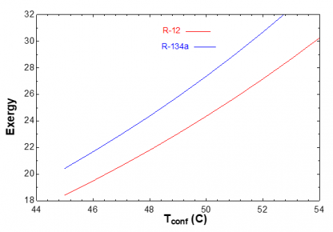
Increasing in the temperature of the condenser will be caused increasing exergy destruction and decreasing coefficient of performance and second–law efficiency, the exergy efficiency dropped as the in condenser temperature increased. Exergy loss increases with increasing condensing temperature for all refrigerants, as seen in Figures 2-5. It is clear because the greater the temperature differential between the ambient and the component, the greater the energy loss. The exergy loss for each refrigerant remains constant in the low temperature zone, whereas it increases in the high temperature region. Exergy losses are likewise larger at higher temperatures for R-14a and R22. Because the greater the temperature difference between the ambient (air) and the system (working fluid), the greater the exergy losses.
Figure 2. Temperature of condenser vs efficiency
Figure 3. Temperature of condenser vs COP
Figure 4. Temperature of condenser vs exergy of capillary
4.1.2 Effect the temperature of surrounding in exergy destruction
From the Figure 6, the temperature of the surrounding is rising, the exergy destruction will be increased.
Figure 5. Temperature of condenser vs exergy destruction
Figure 6. Temperature of surrounding vs exergy destruction
Figure 7. Cooling capacity vs exergy destruction
Figure 8. Cooling capacity vs coefficient of performance
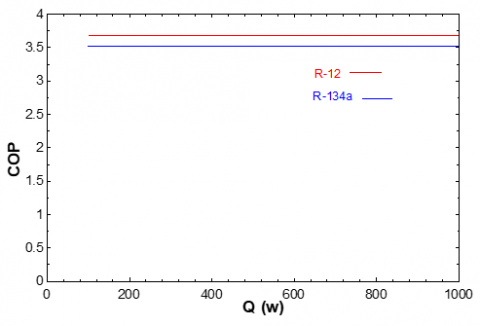
4.1.3 Effect the cooling capacity in the performance of the cycle
The cooling capacity does not consider efficiency or the coefficient of performance if the pressure of the condenser and evaporator remains constant, but it is important for exergy destruction, as shown in Figures 7-9.
Figure 9. Cooling capacity vs efficiency
4.2 Analysis of the calculation of capillary tube
4.2.1 Effect length of the capillary tube
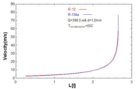
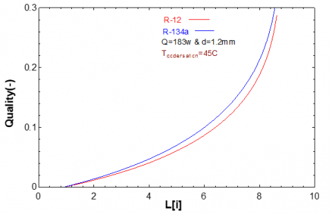
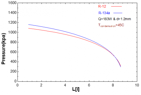
The figures below indicate (Figure 10 to Figure 16) the length of the capillary tube is proportional to the increasing velocity of refrigerant quality. Still, it is inversely proportional to the cooling capacity. These findings agree with the investigation conducted by Javidmand and Hoffmann [12], Khunte and Mishra [13].
Figure 10. Length of capillary tube vs velocity at Q=366.5w
Figure 11. Length of capillary tube vs velocity at Q=183w
Figure 12. Length of capillary tube vs quality at Q=366.5w
Figure 13. Length of capillary tube vs quality at Q=183w
Figure 14. Length of capillary tube vs temperature
Figure 15. Pressure vs length at Q=366.5w
Figure 16. Pressure vs length at Q=183w
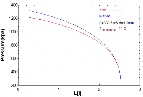
Figure 17. Pressure vs length at condenser temperature=50 C
Figure 18. Pressure vs length at condenser temperature=45 C
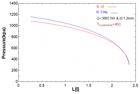
Figure 19. Pressure vs length at condenser temperature=40 C
4.2.2 The effect temperature of the condenser
At compared the results with the research of Jadhav and Agrawal [14], Li and Hrnjak [15], we noted that the temperature of the condenser is one of the most significant parameters that should be taken into account in studying the performance of the refrigeration cycle. The compressor pressure decreases as the length of the capillary tube increases. Cause of increase in pressure due to friction, the specific volume, and velocity increase in the capillary tube. It increases the compressor suction pressure. The blow is proportional to the length of the capillary tube as shown in Figures 17, 18 and 19.
Figure 20. Pressure vs length at the diameter of capillary tube=1.0 mm
Figure 21. Pressure vs length at the diameter of capillary tube=1.2 mm
Figure 22. Pressure vs length at the diameter of capillary tube=1.4 mm
4.2.3 Effect capillary tube diameter
Diameter of the capillary tube is one of the important parameters that should be taken into account in studying the performance of the refrigeration cycle. The figures (Figure 20 to Figure 23) show that the blow is inversely proportional to the length of capillary.
Figure 23. Pressure vs length at the diameter of capillary tube=1.6 mm
1-The operating conditions at the capillary tube's inlet and the refrigerant's thermophysical characteristics, particularly the viscosity, affect the capillary tube's length.
2-The capillary tube's diameter and length are directly proportional. The length is shorter if the diameter is smaller and the length is longer if the diameter is greater.
3- Both refrigerants' performances show the same degree of variation when the conditions remain is the same.
4-In the two-phase region, it is quite different in quality because the viscosity of R-12 is less than R-134a, and length of capillary tube of R-12 is longer than that of R-134a under the same conditions.
|
A |
cross-sectional area of a capillary tube, (m2) |
|
d |
the inner diameter of a capillary tube, (m) |
|
f |
friction factor, dimensionless |
|
$\dot{m}$ |
mass flow rate, (kg/s) |
|
h |
specific enthalpy of the refrigerant, (kJ/kg) |
|
$h_g$ |
specific enthalpy of saturated refrigerant vapour, (kJ/kg) |
|
$h_f$ |
specific enthalpy of the saturated refrigerant, (kJ/kg) |
|
p |
pressure, (Pa) |
|
t |
temperature, (℃) |
|
Re |
Reynolds number, dimensionless |
|
u |
the velocity of the refrigerant, (m/s) |
|
ν |
specific volume, (m3/kg) |
|
$v_g$ |
the specific volume of saturated vapour, (m3/kg) |
|
$v_f$ |
the specific volume of saturated liquid, (m3/kg) |
|
x |
dryness factor of the two-phase flow region, dimensionless |
|
$\mu$ |
viscosity, (kg/m. s) |
|
$\mu_f$ |
the viscosity of a saturated liquid, (kg/m. s) |
|
$\mu_g$ |
the viscosity of saturated vapour, (kg/m. s) |
|
$\Delta \mathrm{L}$ |
incremental length of a capillary tube, (m) |
|
$\rho$ |
density, (kg/m3) |
|
$\tau$ |
shear stress, (N/m2) |
[1] Sharma, P. (2012). Design of capillary expansion device used in vapor compression refrigeration system. International Journal of Latest Research in Science and Technology, 1(1): 45-48.
[2] Peixoto, R.A., Bullard, C.W. (1994). A design model for capillary tube-suction line heat exchangers. Air Conditioning and Refrigeration Center TR-53.
[3] Dawood, A.S., Ibrahim Hasan, S. (2013). Numerical study of Refrigerant flow in capillary tube using Refrigerant (R134a). Al-Rafidain Engineering Journal (AREJ), 21(1): 1-19.
[4] Zareh, M., Shokouhmand, H., Salimpour, M.R., Taeibi, M. (2014). Numerical simulation and experimental analysis of refrigerants flow through adiabatic helical capillary tube. International Journal of Refrigeration, 38: 299-309. https://doi.org/10.1016/j.ijrefrig.2013.07.028
[5] Shokouhmand, H., Zareh, M. (2014). Experimental investigation and numerical simulation of choked refrigerant flow through helical adiabatic capillary tube. Applied Thermal Engineering, 63(1): 119-128. https://doi.org/10.1016/j.applthermaleng.2013.10.040
[6] Chingulpitak, S., Mahian, O., Dalkilic, A.S., Asirvatham, L.G., Wongwises, S. (2019). Sizing charts of helical capillary tubes used in refrigeration and air conditioning. Science and Technology for the Built Environment, 25(1): 1-10. https://doi.org/10.1080/23744731.2018.1490131
[7] Rocha, T.T.M., de Paula, C.H., Cangussu, V.M., Maia, A.A.T., de Oliveira, R.N. (2020). Effect of surface roughness on the mass flow rate predictions for adiabatic capillary tubes. International Journal of Refrigeration, 118: 269-278. https://doi.org/10.1016/j.ijrefrig.2020.05.020
[8] Salem, T.K., Farhan, S.S., Doury, R.R.J.A., Farhan, I.S. (2021). The heat exchangers tubes mineral type effect on the refrigeration system performance using different lengths of the capillary tube. Proceedings of the Institution of Mechanical Engineers, Part C: Journal of Mechanical Engineering Science, 235(22): 6541-6548. https://doi.org/10.1177/09544062211002231
[9] Rabde, N., Pandey, R.K., Varshney, R., Vishwakarma, P. (2022). Comparative performance analysis of R134a & mixture of R134a/hydrocarbon refrigerant flow inside helical capillary tubes in a domestic refrigerator. IJRAR-International Journal of Research and Analytical Reviews (IJRAR), 9(3): 123-135.
[10] Surawattanawan, P., Chutikusol, J. (2023). Mathematical modeling and optimum design for capillary tubes in R-410A Air Conditioner. Journal of Integrated Science and Technology, 11(1): 403-403.
[11] Kaya, S. (2009). Performance comparison on the vapour compression refrigeration system when retrofitting from R22 to R404a. Doctoral dissertation, Marmara Universitesi (Turkey).
[12] Javidmand, P., Hoffmann, K.A. (2015). Numerical-based non-dimensional analysis of critical flow of R-12, R-22, and R-134a through horizontal capillary tubes. International Journal of Refrigeration, 58: 58-68. https://doi.org/10.1016/j.ijrefrig.2015.06.003
[13] Khunte, M.N.K., Mishra, M.R. (2022). Ansys CFX, CFD Analysis: Helical coiled capillary tube. International Journal of Mechanical Engineering, 7(4): 1563-1571.
[14] Jadhav, P., Agrawal, N. (2019). A comparative study in the straight and a spiral adiabatic capillary tube. International Journal of Ambient Energy, 40(7): 693-698. https://doi.org/10.1080/01430750.2017.1422146
[15] Li, H., Hrnjak, P. (2019). Heat transfer coefficient, pressure drop, and flow patterns of R1234ze (E) evaporating in microchannel tube. International Journal of Heat and Mass Transfer, 138: 1368-1386. https://doi.org/10.1016/j.ijheatmasstransfer.2019.05.036