Monaem Elmnifi*![]() | Ahmed Nassar Mansur
| Ahmed Nassar Mansur![]() | Qusay J. Abdul-Ghafoor
| Qusay J. Abdul-Ghafoor![]() | Ahmed A.A.G. Alrubaiy
| Ahmed A.A.G. Alrubaiy![]() | Mustafa Abdul Salam Mustafa
| Mustafa Abdul Salam Mustafa![]() | Mohamed Khaleel
| Mohamed Khaleel![]() | Hasan Shakir Majdi
| Hasan Shakir Majdi![]() | Yasser F. Nassar
| Yasser F. Nassar![]() | Hala J. El-Khozondar
| Hala J. El-Khozondar![]()
© 2023 IIETA. This article is published by IIETA and is licensed under the CC BY 4.0 license (http://creativecommons.org/licenses/by/4.0/).
OPEN ACCESS
This paper proposes a new way to remove salt from water at home by using electricity to heat it. The process involves heating a metal rod using copper coils that are energized by magnets. The metal rod is placed in a tank of salt water. This study examines how water is stabilized and how water flows are represented using numbers and then tested in real life. Testing showed that when a strong electric current of 20 amps is applied to the surface of a steel rod, it boils, reaching boiling temperature. In simpler words, using an induction heating system can heat a water heater to 157℃. By changing the number of rods, the temperature is 21℃ for one rod and 37℃ for three rods connected in series. In an environment where objects were placed next to each other, the highest temperature reached was 28℃. If the temperature of the heating coil goes up from 55℃ to 60℃, the amount of freshwater produced and the efficiency of the system increase. The amount of freshwater goes up from 1.589 liters to 2.403 liters and the efficiency goes up from 56.87 percent to 60.49%. This means that the increase in the quality of freshwater is 39.9%, while the improvement in thermal efficiency is 6.36%. These numbers show that the improvement gets less as the heater temperature goes up. In this model, the highest level of effectiveness in using heat and the amount of clean water produced can both reach 70.44% and 5.65 liters, respectively. Data indicates that the system's performance depends on the evaporator's maximum temperature. This innovative method of heating salt water to turn it into fresh water might be a good, low-cost way to obtain clean water.
induction heating, water desalination, residential environment, numerical simulation
Applications of induction technology for water heating have become more important in a variety of industries, including the culinary, medical, and chemical sectors. Benefits of induction heating include effective heating, sterilization, and the eradication of bacteria and germs. The usefulness of electric induction heating technology for water heating, including heating rates and system efficiency, has been the subject of earlier research. The purpose of this introduction is to present an organized summary of the research that has been done in this area. Numerous studies have evaluated the efficacy of induction heating technology in comparison to traditional heating techniques. A 2017 research found that induction-heating technology outperformed traditional techniques in terms of heating efficiency, saving up to 20% on energy [1]. Additionally, this method has demonstrated the ability to sterilize effectively without the use of chemicals [2]. In terms of heating efficiency and energy savings, comparisons between electric induction heating and conventional solar heating in agriculture have favored the latter [3]. Studies on water desalination have looked into the application of induction technology. When Indian researchers compared induction-heating equipment to alternative methods of desalination, they discovered that induction heating technology provided more economical desalination efficiency [4]. Higher electric current frequencies have been observed to boost induction heating efficiency because of increased magnetic interference [5]. Furthermore, it has been demonstrated that the size of the induction-heating rod influences heating efficiency, with bigger rods yielding higher efficacy [6]. By providing an overview of these studies, it becomes evident that induction-heating technology offers advantages in terms of heating efficiency, energy savings, sterilization, and water desalination. The subsequent sections will delve into the specific findings and methodologies of these studies, shedding light on the potential applications and benefits of induction heating in various fields.
Investigating the influence of electrical induction desalination technology on the desalination of salt-polluted groundwater. The researchers conducted many practical tests on salt-polluted groundwater samples using the desalination process via induction. The researchers concluded after studying the data that the application of electric induction desalination technique can be useful in desalinating brackish water with high efficiency [7]. Examining the effect of electric induction heating technology on water heating and comparing it to different heating technologies. The purpose of this study was to evaluate the efficiency of electric induction heating technology to that of other heating methods, such as gas heating and solar heating. The study involved doing several real tests to heat water in these different methods. The outcomes showed that heating water with electric induction is both effective and affordable [8]. Examining the impact of food heating technology using electric induction. The purpose of the investigation is to investigate the process of heating items such as milk and meat with electric induction heating technology. As part of the inquiry, various practical tests on food samples were conducted using this methodology. These testing included tasting and analyzing the foods. According to the findings of the research [9], using electric induction heating allows for the speedy and uniform preparation of meals.
Conducting research on the influence of electric induction heating technology on the performance of solar thermal systems. The study's purpose was to examine if electric induction heating technology would increase the performance of solar thermal systems. As part of the research, a number of field experiments were conducted using this technology in an effort to improve the efficiency of solar heating systems. The results indicate that the integration of electric induction heating technology may enhance the performance of solar thermal systems [10]. These results suggest that electric induction heating technology for desalination and water heating may be fine-tuned by adjusting heating parameters such as electric current intensity, frequency, and rod diameter.
Examining and evaluating induction heating technology's effectiveness is the primary purpose of this research. We will examine the operation of induction heating and list a few possible uses for it when it comes to heating water. Examining the science behind electric induction heating can help us understand this technology better. The next section gives an example of using one of these heaters to heat water and explains how to operate it. Electric induction water heating will be examined in terms of its many applications, heating rates, and system performance as a whole. By monitoring the temperature of the water using a thermometer, we can evaluate the efficiency of induction heating technology in comparison to more conventional heating methods. We will study the effects of rod size, frequency, and electric current intensity, among other heating variables, on the induction heating system's efficiency. Lastly, the data will be statistically analyzed, and recommendations will be made to enhance the induction heating system's water-heating efficiency.
1.1 Configurations of electromagnetic field devices for water system treatment
The operational parameters for electromagnetic field (EMF) therapy in water systems are determined by the configuration of the device utilized. See Figure 1 for an illustration of the two primary configurations: permanent magnet and solenoid [11]. Permanent magnets can be made from different ferromagnetic compounds, such as iron, nickel, cobalt, or rare earth elements. The electromagnetic fields created by permanent magnets vary in intensity depending on their configuration and the number of magnets utilized. Some magnets are designed with alternating poles, whereas others are designed without. On the other hand, solenoid coils generate a magnetic field inside their cavity when an electric current is passed through them. Depending on the application, solenoids can be constructed in linear, toroidal, or other geometries, and the field strength varies with the number of coils or wire thickness [12, 13]. These devices can be customized or purchased commercially, and the majority of commercial EMF unit producers are based in the United States, Canada, Mexico, and the United Kingdom. These devices create static or pulsing electromagnetic fields that can be perpendicular or parallel to the fluid flow [11].
Figure 1. The two main configurations of EMF devices commonly used in water systems treatment: Permanent magnets (a) and solenoid coils (b)
In the past two decades, extensive testing has been done on permanent-magnet EMF devices and solenoid configurations. However, the efficiency of these devices remains a controversial topic due to the contradictory results obtained from different studies. On the one hand, laboratory tests on NF, UF, and MD laminar frame membranes using permanent magnet treatment suggested that magnetic treatment could form more porous deposits on the membranes [14]. In addition, it has been reported that permanent magnet processing can reduce CaCO3 crystallization on tube walls. On the other hand, several laboratory tests have reported an increase in CaCO3 precipitation in the bulk solution during permanent magnet EMF treatment [15]. A lot of people have looked into how electromagnetic fields can be used on spiral-wound reverse osmosis (RO) units to clean up salty wastewater or artificial complex solutions. For EMF treatment, some studies, like the one by Rouina et al., have found that solenoid coil configurations lead to better salt rejection and permeate flux [16]. However, other studies, like Palmer et al., have observed more deposition of BaSO4 and limited improvement in permeate water flux, with no significant difference in salt permeability [17]. The effectiveness of EMF treatment can also depend on the operating conditions of the RO system, such as the water recovery rate and the presence of spacers. In some cases, putting the solenoid coil's EMF into feed water first has been shown to change the way CaCO3 precipitates, from a surface nucleating scale to a bulk solution powder that doesn't stick to anything. Moreover, the use of a 20-μm filter in the concentric tube of the heat exchanger has been reported to maintain zero fouling resistance over 820 hours. Therefore, the configuration of the EMF device alone is not the primary factor determining its efficiency, and the operating conditions of the RO system should be considered.
A case study in Regina, Saskatchewan, examines the impact of policy changes on rooftop solar PV adoption. Results showed net metering reduces financial returns and lowers potential, while a capital incentive grant increases potential. Understanding policy choices can help policymakers adopt rooftop solar PV [18].
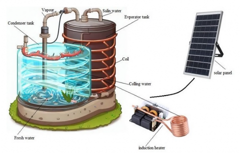
Conventional desalination and water heating systems suffer from several drawbacks, including low efficiency, high energy consumption, air pollution, fuel storage, and exposure to high-temperature environments. Moreover, the use of magnetic materials in such systems often results in the generation of eddy currents within the workpiece, leading to significant ohmic heat losses. To mitigate these challenges, electromagnetic induction heating can be utilized by applying an alternating current. Figure 2 depicts an ideal model of a water desalination system, which comprises a tank designed as an induction heater with a copper coil inside to facilitate the flow of water made of copper. After that, a condenser tank is used to turn the steam that has formed back into liquid water. A solar panel-generated DC alternating current is used to power this system.
Figure 2. Induction desalination model
2.1 Proposed developed model
In this work, a numerical model was created to predict the induction water desalination system's performance at the local level and to assess the impact of technical factors on that performance. A set of the following fundamental equations may be used to represent the induction-desalination model:
2.1.1 The formula for the magnetic field-producing alternating current flowing through a copper coil
$I_{\text {copper }}=V_{\text {solar }} /\left(R_{\text {copper }}+R_{\text {load }}\right)$ (1)
$B_{\text {field }}=\mu_0 * N_{\text {copper }} * I_{\text {copper }}$ (2)
where, A copper coil's alternating current is known as Icopper (in amps). Solar panel-generated alternating voltage is known as Vsolar (in volts). Rcopper: the copper coil's electrical resistance (in ohms). Rload: the electrical resistance of the load (in ohms). μ0: the electromagnetic constant of vacuum (in henry/meter). Ncopper: the number of turns of the copper coil. Bfield: magnetic field of influence (in Tesla).
2.1.2 The equation for calculating the electromagnetic force acting on water
$F_{E M}=V_{\text {water }} * B_{\text {field }} *\left(\nabla \times B_{\text {field }}\right)$ (3)
where, FEM: the electromagnetic force acting on water (in Newton). Vwater: the volume of water to be desalinated (in cubic meters). Bfield: magnetic field of influence (in Tesla). (∇×Bfield): periodic coupling of the magnetic field (in Tesla/meter).
2.1.3 The formula for calculating the force of displacement resulting from an imbalance in the concentration of molecules inside the water
$F_{\text {disp }}=-V_{\text {water }} * \Delta C *(\nabla P)$ (4)
where, Fdisp: the displacement force resulting from an imbalance in the concentration of molecules inside the water (in Newton). ΔC: the difference in concentration between two areas (in parts per million - ppm). (∇P): pressure gradient (in Pa/m).
2.1.4 The formula for calculating the velocity of water flow through the copper coil
$v_{\text {water }}=\pi * d^2 / 4 * q / A_{\text {copper }}$ (5)
where, vwater: the velocity of the water flow (in meters/second). d: diameter of the copper coil (in meters). q: volume produced by desalination (in cubic meters/second). Acopper: The cross-sectional area of the copper coil (in square meters).
2.1.5 The evaporator models
In the model of the evaporator system, the equation for heat can be shown like this:
$Q e v=m r(h e o-h e i)$ (6)
where, mr mass flow rate, (heo-hei) is the amounts of heat energy entering and leaving the refrigerant in the evaporator.
2.1.6 The condenser models
The spiral tube is located in the upper part of the system, through which the steam passes into the tank so that the water condensation process takes place. The tank that stores the water is adequately protected by a thick polyurethane insulating covering. As a result, only a minimal quantity of heat is lost from the water tank to the environment. The following factors influence the heat transmission process in the condenser-coiled tube:
$Q e v=m r(h c i-h c o)$ (7)
where, mr is the vapor's mass flow rate, hci is the enthalpy at the spiral tube's intake, and hco is the enthalpy at the exit. The heat transferred from the spiral condenser coil to the water is represented by the following equation:
$Q w=c w \cdot m w(T c o-T c i)$ (8)
where, cw is the specific heat capacity of water, mw is the flow rate, Tci is the beginning water temperature, and Tco is the end water temperature. The spiral condenser coil uses a precise relationship to transmit heat to the water.
$Q w=U c \cdot A c(T c-T w)$ (9)
where, Qw represents the thermal energy of the water, Uc represents the total heat transfer coefficient, Ac represents the heat transfer area of the condenser, Tw represents the average temperature of the water, and Tc represents the temperature of the refrigerant.
2.2 Experimental setup of the model
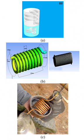
This study's experimental setup contains a steam compression cycle and a water heating system that includes an evaporator and a water tank with a water-immersed condenser. to transport the energy generated from the coil to the water in the tank and increase its temperature to make steam. A coupling system prototype was created based on the schematic model presented in Figure 2 to examine the impact of coil shape on the operating parameters of desalination. As illustrated in Figure 3, the topic of this work is a water tank with a submerged helical condenser coil. The helical coil arrangement is described in detail. Table 1 shows a 50-liter plastic water tank with a stainless-steel wall and a 50-mm-thick polyurethane thermal insulation layer. The storage tank is properly insulated with glass wool during the experiment, and heat loss to the surrounding environment is ignored. Throughout the heating process, the entire amount of water in the tank is maintained. A steady room temperature of 20℃ is maintained.
This technology is great for controlling temperature and managing charges for solar batteries. Flat-type natural solar heating systems, hybrid PVT solar thermal collectors, and solar induction systems are all good options for heating using the power of the sun. Each of them has different advantages over the others when it comes to how well they work and how much they cost. They also vary in terms of how quickly they can be installed and how much it will cost to do so. The solar induction system is simple to take care of and has safety features for temperature. Solar power systems can be used both during the day and at night. It also has the option to charge with electricity, so it can be used in the rain too. Figure 3(a), (b) shows the shape of the 3D axis simulation used in the study to represent induction heating. Table 1 displays the measurements for the coil's length, inner and outer sizes, flow rate, and temperature. The first attempt to see if the best coil design was a good match was tested using computer models to check if it was appropriate. We ran simulations using a heating system that uses electromagnetic induction. The system had a coil that moved back and forth to heat the object. It operated at a frequency of 50 Hz and had a power of 3 kW. We tested the system at various temperatures, starting at 11℃ and going up to 55℃. As you can see in Figure 3(b), the tube had a flow of 0.114 kg/s, and the vessel had a flow of 0.135. In Figure 3(c), we have tested a system that heats water for domestic use using an experiment. It consists of a vessel and a copper coil connected to a battery power supply for heating. We used a frequency of 50 Hz and a coil that had 300 turns. We also used a copper tube with a diameter that matched the results of the simulation. The results were compared to what the simulation showed, and we watched how the heater acted when we used two different voltages. The boiler temperature for the one-phase system was 27℃, and for the two-phase system, it was 77℃. The amount of water flowing was 1.33 kg/h. Moreover, the effectiveness of operations was 90%. Besides the coil length, how long it was heated, and the size of the tank, the experiment and the simulation results matched.
Table 1. Operational condition values of the induction coil for the lower part of the model
|
Parameters |
Symbols |
Values |
|
Coil diameter |
DC |
0.420 m |
|
Tube inner diameter |
dci |
0.005 m |
|
Tube outer diameter |
dco |
0.006 m |
|
Coil height |
H |
0.39 m |
|
Coil pitch |
hc |
0.04 m |
|
Length |
LC |
6.075 m |
|
Number of turns |
N |
14 |
|
Water flow of tube side |
0.114 kg/s |
|
|
Water flow of vessel side |
0.135 kg/s |
|
|
Inlet temperature of tube |
35-59℃ |
|
|
Outlet temperature of tube |
23-45℃ |
|
|
Inlet temperature of vessel |
12-20℃ |
|
|
Outlet temperature of vessel |
15-41℃ |
|
Figure 3. Structure of the desalination tank: (a) The geometry of the model, (b) The bottom part of the system is the induction tank and (c) The experimental part of the system
An electrically conductive substance can be heated using the method of induction heating, which uses electromagnetic induction. Research has looked at this heating method's potential for water desalination, particularly on a domestic scale, and it has been used in a variety of industrial procedures.
Experiments and simulations were conducted using software and hardware we developed. We experimented for three days. Each trial lasts for 8 hours, starting at 9:00 a.m. and ending at 5:00 p.m. local time. In tests, we use an electric heater to make sure the evaporator temperature is kept at 50℃. In simple words, the main goal of experiments is to prove the accuracy of computer simulations. The results of experiments and computer simulations are compared.
3.1 Heat distribution
The way heat is distributed in an induction heating system is a critical factor that influences the process's efficacy and efficiency. Optimizing the system's performance requires an understanding of how heat is dispersed inside the system.
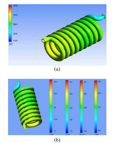
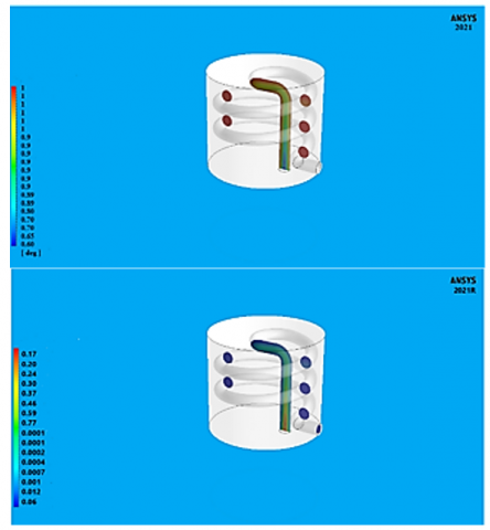
Figure 4. The heat distribution of the coil with changing heating time
Figure 4(a) shows how heat diffuses in a sample coil with a diameter of 16 mm and a length of 200 mm. This coil is used to heat the water at the bottom of the heater. The strongest magnetic field at the surface occurs at the end, and the concentration creates a dimming effect when there is a changing magnetic field, giving rise to an eddy current. This event shifts the magnetic force between the inductor and the workpiece. The strongest magnetic field exists between the coil and the workpiece. The workpiece is centered between the ring and the workpiece. Because the rods and coil are spaced properly, the coil creates an increasing magnetic field. Heat is generated when the ring becomes hot, and the temperature can change from 13℃ to 40℃. The length of the coil affects the heating range. Figure 4(b) shows the temperature circulating inside a tube with a width of 50 mm and a length of 200 mm. Temperatures were taken at one, two, four, and seven-minute intervals. The eddy current warms the tube in this scenario, while the transmitted heat raises the temperature of the object being worked on. The electromagnetic field has a substantial influence in these circumstances since the temperature differential is 3 degrees.
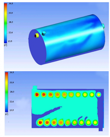
Figure 5. Heat spreads through a piece of the vessel
Figure 5 shows how heat spreads through a piece of vessel 120 mm in diameter and 250 mm long. The strong vortex pulls the current off the sidewall of the surface. The eddy current moves through a thin layer of skin and collects on the outer surface. The current decrease in the inner region is due to the impact of skin depth. When the temperature rises, the current flow at the surface increases. Heat transfer from the surface heats the atmosphere or air inside. In general, the heating defect of the end and edge occurs when the current flowing at the corner of the workpiece is too little. The figure also shows how the temperature is distributed around a cross-section of a tank with a diameter of 120 mm and a length of 250 mm. The eddy current heats and increases the temperature as the temperature decreases at the edges of the region and increases in the center. The average temperature ranges between 12 and 40℃.
3.2 Temperature and mass transfer rate
The proposed model is used to desalinate water by steam exchange and condensation in a tube. The external water is exchanged at the top of the form. Details of this are shown in Figure 6. The process of transferring mass through a pipe and the expected temperature change are explained by the figure. Heat exchange and steam condensation are two prominent water desalination processes that employ steam to separate fresh water from pollution and other impurities. Water desalination by steam exchange and condensation entails sending external water via a conduit that is heated with hot steam. When cold water comes into contact with the hot tube, a heat exchange between the steam and the water occurs, causing part of the water to transform into steam and the steam to condense in the tube.
Figure 6. The temperature and mass transfer rate at the top of the model
Figure 7. The produced rate of steam and the amount of water
Figure 7 shows how steam is produced using a tube and then condensed to produce water. The use of steam in water desalination is an excellent way to get rid of harmful substances and salts present in untreated water. The method of manufacturing the pipes can vary depending on the purpose for which they will be used. The tube can be straight or curved to provide more heat exchange area and make condensation better. You can use more pipes to process more water and produce more fresh water.
In conclusion, temperature and mass transfer rates are related and important parameters in thermal processes such as the desalination of water. Numerical simulations, theoretical modeling, and real-world experiments are frequently combined in optimization.
3.3 Fresh water and thermal efficiency
At the end of the experiment, the fresh water generated is collected in a container and measured. Table 2 displays the findings of three days of freshwater tests. The ambient temperatures for each experiment are also included in the table. The amount of fresh water generated is also estimated mathematically, and the results are displayed in a table. The table shows that the experimental and numerical results differ only a little. The difference is around 10%. The numerical and experimental findings are in good agreement. In the current work, the average productivity of the system per day was 5.6 kg/day.m2.
Table 2. The simulated and experimental product fresh water rate
|
Experiment [Day] |
Ambient Temperature [℃] |
Fresh Water Produced [liter] |
|
|
Experiment |
Simulation |
||
|
1 |
25-32 |
1.15 |
1.22 |
|
2 |
23-34 |
1.18 |
1.20 |
|
3 |
26-35 |
1.20 |
1.24 |
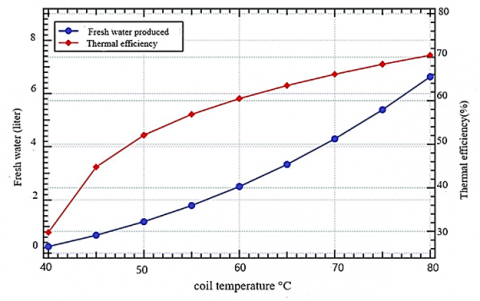
Figure 8. Effect of induction coil temperature on performance
A study was done to see how different factors affect how well a system works. This case study will use two performance measurements. The first thing we are talking about is how much fresh water is made by the system. Having a good amount of fresh water makes things work better. The second thing to consider is how well something can turn heat into useful energy. This thing measures how well energy is used to make clean water. If a machine has a higher thermal efficiency, it means it works better. As mentioned before, the current system uses solar energy to heat up using induction. The temperature at which the coil functions is important. Therefore, we need to understand how hot the induction coil gets and what happens because of that. The system's performance is tested by simulating it at various heater temperatures. In the simulation, we will use the measured temperature as the condition at the edges. The heater can be set to temperatures between 40℃ and 80℃. The simulation will begin at 9:00 in the morning and finish at 4:00 in the afternoon local time. The diagram in Figure 8 shows how well the system is using energy and how much clean water it is making. The graph clearly shows that the heat from the coil significantly affects how well the system works. Increasing the temperature of the heating coil can make more clean water with better efficiency. However, when the temperature of the heating coil goes up, the efficiency rate and the improvement in freshwater decrease. For instance, when the heating coil temperature goes up from 50℃ to 55℃, the amount of freshwater produced and the efficiency of capturing heat increase from 1.182 L to 1.789 L and from 50.09% to 55.87%, respectively. This means that the quality of freshwater has improved by 51% and the efficiency of heat has improved by 9.17%. If the temperature of the heating coil goes up from 55℃ to 60℃, the amount of freshwater produced and the efficiency of the system increase. The amount of freshwater goes up from 1.589 liters to 2.403 liters, and the efficiency goes up from 56.87 percent to 60.49%. This means that the increase in the quality of freshwater is 39.9%, while the improvement in thermal efficiency is 6.36%. These numbers show that the improvement gets less as the heater temperature goes up. In this model, the highest level of effectiveness in using heat and the amount of clean water produced can both reach 70.44% and 5.65 liters, respectively. Facts show that the highest temperature in the evaporator is important for how well the system works.
Figure 9. Effect of condenser temperature on fresh water
Figure 9 shows how the temperature of the condenser affects how the system operates. This shape shows that when the temperature of the condenser decreases, it leads to higher performance. For example, when we have a condenser whose temperature is 40℃, its efficiency in producing heat and freshwater is 51.79%, and the volume of water produced is 1.831 liters. If the temperature of the condenser rises to 45℃, the thermal efficiency will be 42.08%, and it will produce 1.281 liters of fresh water. More simply, thermal energy and freshwater production will decrease by 18.7% and 30%, respectively. This fact means that the temperature of the cooling device greatly affects the way the system operates. The lower the temperature of the condenser, the higher its quality. On-site, there are strict limits on the condenser temperature. It is strongly affected by the ambient temperature. For the system to work well, the condenser must be designed to be close to the ambient temperature.
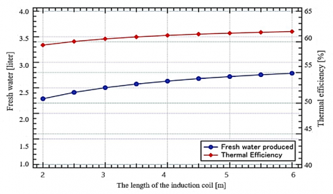
Figure 10. Effect of condenser temperature on fresh water
The heater vessel has a diameter of 120 mm wide and 250 mm long. Inside the container, a coil is 16 mm wide and 200 mm long. To see how the heater's size affects it, we will make the heating coil longer. We will change the length from 2 m to 6 m, but keep the temperature on the surface the same at 50℃. The temperature of the surroundings will be added to the measurement as a boundary condition. The results of how the size of the heater surface affects something are displayed in Figure 10. In the picture, they measure the heat coil's length instead of its surface area. The graph shows that when the surface area of the heating coil gets larger, the thermal efficiency and the amount of freshwater produced also increase. However, the rate of improvement is not very high. For instance, if the heating coil size is increased from 3 m to 6 m, the efficiency of heat generation will improve slightly from 61.49% to 61.68%. By making the same improvement, the amount of clean water will go up from 2.503786 liters. These numbers show that the increase in heat efficiency is 1.9%, and the increase in the amount of clean water made is 11.3%. Therefore, even though there is a small change, it does not make much of a difference. Simply put, the size of the heater's surface has little bearing.
Optimizing the process for energy efficiency is a major problem because induction heating may be an energy-intensive procedure. It is imperative to use materials that are resistant to high temperatures and are compatible with the corrosive properties of saltwater. Technology adaptation for home usage necessitates taking size, cost, and maintenance ease into account. It is important to give considerable thought to both the desalination process's overall environmental impact and the disposal of concentrated brine.
In conclusion, this paper presents a novel approach for saltwater desalination at home through the utilization of electricity for heating. The proposed method involves the use of copper coil-induced magnetization to heat a metal rod, which is then immersed in a tank of saltwater. The study focuses on examining the stability of water and representing water flow using numerical simulations, followed by real-life testing. The experimental results show that heating water successfully involves delivering a high electric current of 20 amps to the surface of a steel rod until it reaches boiling point. A water heater may be made to reach a temperature of 157℃ by using an induction heating technology. A single rod can have a temperature of 21℃, while three rods linked in series will have a temperature of 37℃. The temperature can be changed by changing the number of rods. The highest temperature that was measured when there were things close by was 28℃. Moreover, raising the heating coil's temperature from 55℃ to 60℃ increases the amount of freshwater generated as well as the system's efficiency. The efficiency increases from 56.87 percent to 60.49 percent, and the freshwater production increases from 1.589 liters to 2.403 liters. It is important to remember, nevertheless, that as the heater temperature rises, the rate of improvement decreases. According to the model, the maximum efficiency for producing clean water and using heat may be achieved at a rate of 5.65 liters and 70.44 percent, respectively. Overall, this innovative approach demonstrates promising potential as an affordable and effective method for obtaining clean water through heat-based desalination. The findings highlight the significance of the evaporator's temperature in determining system performance. This research offers valuable insights into a novel means of converting saltwater into freshwater, which could have significant implications for addressing water scarcity and providing accessible clean water resources.
The study provides useful methods for resolving domestic water scarcity challenges in addition to advancing our understanding of induction heating for water desalination. The proven scalability, energy efficiency, and environmental advantages highlight this technology's potential contribution to the availability of fresh water supplies that are both accessible and sustainable.
This model is considered applicable in times when traditional energy sources are not available, because it works with a renewable source, which is solar energy with a storage battery.
1. More experiments and investigations can be explored to achieve a deeper understanding of the proposed desalination process. The effect of changing various factors such as the amount of salt water, the electrical current used, and the arrangement and number of metal rods on the efficiency of the system and the amount of fresh water produced can be studied.
2. Energy consumption may be decreased and system efficiency can be raised. Other methods, including better heat distribution and copper wire design, can be researched to increase the amount of heat required to turn salt water into fresh water.
3. This approach may have broader uses in a variety of contexts, such as distant communities, residences, and businesses. Research may be done on how to make the process better and modify it to suit various water requirements, such drinking water desalination and agricultural irrigation.
4. Research ought to be done on the effects this strategy will have on the economy and the environment. It is possible to evaluate the system's possible effects on the environment, including how waste and water resources are produced. To compare the implementation costs of the system to those of comparable desalination systems that are currently on the market, an economic evaluation may be carried out.
[1] Sharma, R.K., Singh, S.K. (2017). Design and performance analysis of induction heating system for water heating. International Journal of Applied Engineering Research, 12(9): 1809-1813.
[2] Patil, C.S., Patil, S.R., Patil, S.C. (2012). Induction heating: An innovative method for water disinfection. Journal of Water Resource and Protection, 4: 123-128.
[3] Yadav, A.K., Kumar, M., Singh, S.K. (2018). Induction of heating for water heating: A comparative study. International Journal of Scientific and Engineering Research, 9(4): 133-138.
[4] Pandey, K.M., Kumar, S., Kumar, N. (2011). Induction heating: A novel method of water desalination. Desalination, 274(1-3): 96-100.
[5] Tanaka, Y., Hasegawa, K., Watanabe, Y. (2016). Effect of high frequency induction heating on water heating efficiency. Journal of Thermal Science and Technology, 11(2): 1-10.
[6] Sahu, N.K., Parhi, P.K., Parida, S.K. (2014). Experimental investigation of induction heating for water heating. International Journal of Engineering Research and Applications, 4(2): 6-9.
[7] Gaikwad, R.W., Kale, B.B., Bhanvase, S.A. (2017). Desalination of groundwater by induction heating: Experimental investigations and design considerations. Applied Energy, 185(1): 309-318.
[8] Lin, C.H., Chen, C.H. (2014). Induction heating for domestic hot water production: A comparative study between gas-fired boilers and induction water heaters. Energy Conversion and Management, 83: 250-256.
[9] Kuo, B.C.W., Ramaswamy, H.S. (2018). Induction heating of foods: Principles, applications, and related properties - A review. Journal of Food Engineering, 220: 1-14.
[10] Zhao, F., Zhao, Y., Li, X. (2016). Induction heating for solar thermal energy systems: A review. Renewable and Sustainable Energy Reviews, 64: 706-718.
[11] Ambashta, R.D., Sillanpää, M. (2010). Water purification using magnetic assistance: A review. Journal of Hazardous Materials, 180(1-3): 38-49. https://doi.org/10.1016/j.jhazmat.2010.04.105
[12] Li, X.L., Yao, K.L., Liu, H.R., Liu, Z.L. (2007). The investigation of capture behaviors of different shape magnetic sources in the high-gradient magnetic field. Journal of Magnetism and Magnetic Materials, 311(2): 481-488. https://doi.org/10.1016/j.jmmm.2006.07.040
[13] Britcher, C.P., Ghofrani, M. (1993). A magnetic suspension system with a large angular range. Review of Scientific Instruments, 64(7): 1910-1917. https://doi.org/10.1063/1.1143976
[14] Huchler, L.A., Mar, P.E., Lawrenceville, N.J. (2002). Non-chemical water treatment systems: Histories, principles and literature review. In International Water Conference, Pittsburgh, PA, USA, pp. 2-45.
[15] Jassim, L., Elmnifi, M., Elbreki, A., Habeeb, L.J. (2022). Modeling and analysis of home heating system material performance with induction using solar energy. Materials Today: Proceedings, 61: 852-859. https://doi.org/10.1016/j.matpr.2021.09.302
[16] Rouina, B.B., Hamdaoui, O., Chiha, M. (2010). Electromagnetic field-enhanced reverse osmosis for desalination: Experimental investigation. Desalination, 264: 1-8.
[17] Palmer, K.L., Sun, K., Kim, Y.C. (1999). Electromagnetic fields for reducing scaling potential in reverse osmosis. Desalination, 126: 163-172.
[18] Dolter, B., Seatle, M., McPherson, M. (2023). When the sun sets on net metering: How the cancellation of net metering impacted the potential adoption of residential rooftop solar photovoltaics in Regina, Saskatchewan. Challenges in Sustainability, 10(1): 47-76. https://doi.org/10.12924/cis2023.10010047