Anas Alwatban![]() | Hesham Othman*
| Hesham Othman*![]()
© 2023 IIETA. This article is published by IIETA and is licensed under the CC BY 4.0 license (http://creativecommons.org/licenses/by/4.0/).
OPEN ACCESS
This study presents a numerical analysis of turbulent air flow through a rectangular duct fitted with two perforated vertical baffle plates, focusing on flow characteristics and pressure distribution. The analysis employs two-dimensional differential equations, solved using the finite volume method. The k-ε turbulence model, implemented in Fluent software, elucidates the turbulence dynamics. Boundary conditions, including the entrance velocity field and exit atmospheric pressure, were varied to comprehensively evaluate the system. The model's validity was established against experimental data at a Reynolds (Re) number of 87300, demonstrating excellent comparability at a distance of 0.525 m from the duct entrance. The research aims to investigate the effects of different Re numbers (10,000, 20,000, and 30,000) on various parameters in a duct equipped with two perforated, nozzle-shaped vertical baffles, each comprising eight trapezoidal sections forming seven nozzles. Parameters analyzed include the velocity profile, pressure drop, turbulent kinetic energy, dynamic pressure coefficient, and skin friction coefficient. The study finds that the insertion of perforated vertical baffles enhances mixing, particularly at higher Re numbers. Axial velocities attain maximum values above the bottom baffle and below the top baffle, with multiple re-circulation zones observed at strategic locations including above, below, and behind the baffles. Significant findings include the occurrence of maximum vertical velocity values at Re=30000 upstream of the bottom baffle, and a substantial re-circulation zone immediately upstream of the upper baffle. The channel's thermal enhancement factor is noted to improve with decreasing levels of skin friction as the Re number increases. Pressure values rise at the junctions where the duct's inner walls meet the upper surfaces of the baffles. Turbulent kinetic energy across the duct is categorized into three distinct zones based on the Re number: Zone 1, between the entry and the first baffle, exhibits minimal turbulence influence; Zone 2, located between the baffles, shows a peak turbulent kinetic energy of about 3 m²/s² near the nozzle exits and the bottom of the top baffle; Zone 3, extending from the second baffle to the outlet, records the highest turbulent kinetic energy rate at a Re number of 30,000.
CFD, nozzle-shaped, vertical baffles, turbulent flow, coefficient of skin friction, turbulent kinetic energy, rectangular channel
In the realm of heat exchangers, the efficacy of heat transfer is critically dependent on various design factors, one of which is the incorporation of baffles. The strategic placement of baffles, varying in shape, size, and configuration, significantly amplifies turbulence levels, thereby enhancing the rate of heat exchange. The integration of baffles along the walls of channels fundamentally alters the flow dynamics, predominantly by inducing the formation of vortices. These vortices play a pivotal role in improving heat transfer rates.
In terms of air solar exchanger channels, optimizing the heat exchange between air and heated surfaces is a complex task addressed using diverse methodologies. One such approach involves the addition of fins or baffles within the channel. These elements serve as obstructions and can be strategically positioned on either the top, bottom, or both surfaces of the channel walls. Their presence not only creates turbulence but also expands the surface area available for heat exchange. Consequently, this leads to a marked improvement in performance, characterized by a significant increase in the efficiency of heat transmission.
The design and behavior of turbulent flow in ducts with baffle plates have been extensively studied through various numerical and experimental research endeavors. The concept of incorporating obstacles in heat exchanger channels to enhance flow dynamics has been a focus since Berner et al. [1] explored the effect of baffles as simple impediments in 1984.
Demartini et al. [2] conducted a detailed study on turbulent air flow in a rectangular duct with two baffle plates positioned on opposing walls. It was observed that significant pressure regions were established upstream of both plates, while downstream regions exhibited low-pressure zones. This phenomenon was closely associated with the formation of recirculation regions linked to these pressure variations.
A noteworthy numerical analysis by Benzenine et al. [3] investigated air turbulence in a duct of rectangular cross-section, equipped with two waved fins positioned consecutively on opposing walls. Employing the k-ε model for low Re number turbulence, they discovered that the inclusion of waved baffles reduced skin friction by 9.91% at a baffle angle of 15°, and even more in other configurations. A decrease in pressure loss by 10% was noted in comparison to baffles with a plane shape. They concluded that the optimal re-circulation zone magnitude and desired time duration were achieved when the waved baffles were used vertically (angle=0°), resulting in high velocity at the channel's exit and reduced pressure losses.
In recent research, the dynamics of airflow in rectangular cross-section ducts featuring baffles with gaps have been scrutinized. Jamil et al. [4] conducted a comprehensive numerical analysis of turbulent airflow in a duct incorporating various baffle plates. Utilizing FLUENT and the k-ε turbulence model, they solved the governing equations through the finite volume method. Their study, spanning Re numbers from 44,000 to 176,000, examined normalized velocity profiles and skin friction coefficients at multiple locations for both plane and trapezoidal baffle plates. The findings revealed that the pressure decrease was most pronounced upstream and peaked downstream of the channel for both baffle types. Additionally, when four baffles were alternately positioned on the lower and upper surfaces in the trapezoidal configuration, an increase in axial velocity compared to plane baffles was observed, alongside notable effects of baffle height and thickness on boundary layer separation.
El-Said [5] embarked on an innovative study to enhance heat transmission and reduce flow resistance in a solar air heater (SAH) using a novel absorber plate design. This design was computationally evaluated using three-dimensional Navier-Stokes software simulations. The research focused on assessing the thermal efficiency and temperature distributions within the SAH. The study explored the effects of various parameters, including the inclination angle of the baffle plate, hole diameter, and air mass flow rate, on the pressure differential and thermal efficiency. The application of curved perforated baffles in a solar air collector is a significant highlight of this paper.
The findings indicated that the newly developed technology was apt for building heating applications, and the numerical model used could effectively predict outlet temperature and pressure drop. The study observed an increase in the thermal efficiency of the SAH with higher air mass flow rates and larger hole diameters, while an increase in baffle angle led to a decrease in efficiency.
Benosman and Amraoui [6] conducted research on the performance of a typical solar air collector at varying Re numbers. A mathematical model was developed to analyze the impact of Re Number on velocity fields, turbulence, Nusselt profiles, and friction factor. The results showed an increase in heat transmission rate with rising Re numbers. However, the authors emphasized the need for a technico-economic analysis to ascertain the actual and usable energy requirements, aiming to minimize energy loss.
In another study, Menni et al. [7] conducted a numerical analysis of a heat exchanger equipped with S-shaped baffles designed to create longitudinal vortices, thereby enhancing turbulent convective heat transfer. The objective was to improve the convective heat transfer of the heat exchanger. The CFD study revealed that the flow divided into three distinct streams at the sharp head of the front baffle, serving as a division point. It was observed that the average velocity was low near the baffles and varied in these regions. The velocity values were predominantly higher along the upper channel wall, starting from the left upper side of the final baffle towards the exit.
In the domain of heat exchanger channels incorporating baffles, Salmi et al. [8] conducted a computational analysis aimed at enhancing heat transfer in air flows around triangular and rectangular turbulators. Their study revealed highly turbulent flows and the formation of numerous vortices in different parts of the exchanger, emphasizing the efficacy of rectangular-shaped turbulators in augmenting heat transfer between the fluid and heated areas. The research concluded that the use of rectangular turbulators in baffled channels resulted in higher fluid temperature values at the exit, underscoring their significance in improving heat transfer efficiency.
Mahdi et al. [9] explored three strategies to enhance the performance of baffled heat exchangers: perforation of obstacles, baffle reconfiguration, and baffle inclination. The first method involved creating pores in the baffles to reduce pressure in flow zones. The second approach entailed restructuring the baffle design to achieve higher axial velocity components and lower vertical velocity components. The third strategy employed an angled baffle design to enhance temperature gradients and vortex formation. Using air as the working fluid, this study focused on examining the velocity profile and pressure drop in a rectangular duct equipped with two baffle plates. The findings indicated that the large vortex was divided into two smaller vortices by the minor flow through the center hole of the perforated baffle. These outcomes highlighted the influence of different obstacle models on the dynamic pressure field. The study observed that the top side of the inclined plate facilitated fluid flow towards the exit by creating parallel lines following the block that caused the stream to split at its right edge, resulting in a large recirculation cell.
Menni et al. [10] conducted a quantitative investigation into the forced convection and two-phase flow of hydrogen gas in a solar channel, which utilized fins and baffles, for Re numbers ranging from 5000 to 25000. Their study revealed that dynamic pressure values were notably higher near the top and bottom margins of the baffle, while being lower at the right and left edges. Furthermore, regions adjacent to the duct walls, specifically between the front edges of the fins and the rear side of the baffle, exhibited significant dynamic pressure values.
With an increase in Re number, there was a corresponding rise in the thermal enhancement factor. At the highest Re number of 25,000, the thermal enhancement factor reached approximately 4.18, which was 2.75 times greater than the factor reported for standard gaseous fluid (air) applications. The study concluded that the proposed structure, with its high flow velocity of hydrogen gas as a heat transfer fluid, enhanced heat transfer and dynamic pressure while simultaneously reducing skin friction values. This improvement contributed to an increase in the overall thermal enhancement factor of the channel.
In another study, Boonloi and Jedsadaratanachai [11] performed a numerical analysis focusing on heat transfer processes and flow topologies in a square-form channel heat exchanger equipped with double-inclined baffles. The study aimed to explore the influence of baffle height and distance relative to duct height, as well as the angle of flow attack, on flow topologies, heat transfer characteristics, and thermal performance. The Re numbers in this study varied from 100 to 2000. The researchers concluded that the presence of double-inclined baffles, which generated vortices and impacting streams disrupting the thermal boundary layer at the surfaces, was a significant contributor to the increased heat transfer rate. The optimal thermal enhancement factors for the square channel with double-inclined baffles were found to be approximately 3.87 at a distance to duct height ratio of 1, an angle to duct height of 30°, a Re number of 2000, and a height to duct height ratio of 0.15.
Razavi et al. [12] assessed the impact of perforated and inclined baffle plates on thermal laminar flow in rectangular channels. Their findings indicated that the use of perforated plates, as compared to plain ones, enhanced the Nusselt number and reduced the friction factor. Notably, the effectiveness of the baffles increased with rising Re numbers. Among the configurations studied, the 135° perforated baffle emerged as the most favorable, significantly improving heat transfer while concurrently reducing the friction factor.
Menni et al. [13] presented a Computational Fluid Dynamics (CFD) analysis of heat transfer and fluid flow in a solar air duct of rectangular cross-section equipped with baffles. This study particularly focused on the influence of two distinct S-shaped baffle orientations on fluid flow and heat exchange within the channel. The research encompassed a comprehensive examination of streamlines, velocity magnitude, turbulent viscosity, dynamic pressure coefficient, turbulent kinetic energy, turbulent intensity, temperature field, local and average normalized Nusselt numbers, normalized skin friction factor and coefficient, and thermal performance factor. The results elucidated that the inclusion of S-shaped baffles significantly intensified the thermal transfer rate in the channel while also increasing friction loss. These effects were found to be contingent on both the orientation of the S-shaped baffles and the Re number. The study concluded that the S-upstream baffle configuration yielded higher rates of heat transfer and friction loss compared to the S-downstream baffle. The optimal thermal performance factor, recorded at the highest Re number with the S-downstream baffle orientation, was approximately 1.513.
In another study, Ameur et al. [14] explored the efficiency of perforated baffles in a plate-fin heat exchanger through numerical simulations. Their investigation focused on the effects of circular and elliptical perforations on pressure drop, heat transfer coefficient, and thermal performance factor in the heat exchanger. The study found that for low viscosity fluids across all Re numbers (1-300), elliptical perforated baffles exhibited superior performance with a 63.4% increase in thermal performance factor compared to circular ones. For highly viscous fluids, the elliptical perforations outperformed circular ones by approximately 25% at low Re numbers and 27% at high Re numbers. The overall thermal performance factors for circular and elliptical perforations were approximately 1.55 and 1.74, respectively.
Liang et al. [15] conducted a comprehensive study to investigate the impact of various baffle configurations on frictional resistance, flow patterns, heat transfer coefficient, and temperature distribution in triangular cross-section ducts with cross-corrugated structures. Their research highlighted the efficacy of baffles in expanding the heat transfer area, altering flow direction, intensifying fluid disturbance, and enhancing heat transfer efficiency. The study reported a maximum increase in heat transfer efficiency of 13%, underscoring the effectiveness of baffles in thermal applications.
A study by Krishna Putra and Ahn [16] focused on the influence of perforated and inclined baffles on heat transfer and friction behavior in a rectangular channel with air flow. The findings indicated that both the number of baffle holes and the Re number significantly affected the friction factor and heat transfer efficiency. The study observed optimal heat transfer performance with a 3-hole baffle configuration, where the friction factor decreased as the number of holes in the baffles and the Re number increased.
In another investigation, Ameur [17] examined the effects of corrugated baffles on thermal and flow fields in a rectangular channel heat exchanger. Computational analysis revealed that using a corrugation height of 50% and varying the corrugation angle from 0° to 45° yielded the best overall performance factor. The total performance factor increased from 1.27 to 1.53 when the corrugation angle was changed from 0° to 45°, demonstrating the potential of corrugated baffles in enhancing heat exchanger efficiency.
Dutta and Dutta [18] conducted an experimental study to investigate frictional loss and heat transfer behavior of turbulent flow in a rectangular duct with iso-flux heating from the top surface wall. Their research primarily focused on the impact of various sizes, placements, and orientations of inclined baffles on internal heat transfer enhancement. They identified the optimal perforation density that led to the highest heat transfer coefficients. This optimal perforation facilitated a powerful jet impingement technique from the constricted channel at the bottom, alongside other advanced heat transfer methods. Furthermore, their study revealed that the use of solid baffles, as opposed to perforated ones, could result in diminished heat transfer coefficients.
Eiamsa-ard et al. [19] explored heat transmission and periodic laminar flow in a three-dimensional duct equipped with triangular wavy baffles. Their investigation encompassed three different baffle attack angles - 30, 45, and 60 degrees - for Re numbers ranging from 100 to 1000. Each wavy baffle generated two counter-rotating vortices. The baffles set at 30° and 45° angles produced vortices of approximately equal strength, significantly stronger than those generated by 60° baffles. Under identical conditions, baffles with 30° and 45° angles yielded similar Nu/Nu0 ratios, substantially higher than those of 60° baffles. In terms of friction, the 30° baffles generated less than those at 45° and 60°. The highest thermal performances observed were 2.3, 2.2, and 1.88, respectively, for baffles with attack angles of 30°, 45°, and 60°.
Previous research has predominantly focused on the dynamic behavior of flow in rectangular channels with various shapes and configurations of baffles. The emphasis has been on the effects of vortex generator shape and slope on the dynamic structure of flow and heat transfer enhancement. However, the novel shape of perforated nozzle vertical baffles has not been explored. The objective of this research is to analyze the influence of different Re numbers on the velocity profile, pressure drop, and turbulent kinetic energy in a rectangular cross-section duct equipped with two perforated vertical baffle plates shaped like nozzles, each consisting of eight trapezoidal sections forming seven nozzles. Air is used as the working fluid in this study.
The assumptions were that the flow field under study is two-dimensional and incompressible. Since the profile of velocity at the duct’s inlet is consistent, it is assumed that the physical characteristics of air remain constant. Therefore, the following governing equations are necessary to solve numerically this flow field. They are the momentum and continuity equations. The continuity equation for steady conditions, assuming incompressible flow and lacking a source term, is:
$\frac{\partial(\rho u)}{\partial x}+\frac{\partial(\rho v)}{\partial y}=0$ (1)
where, u is the fluid velocity in x-direction (m/s) and v is the fluid velocity in y-direction (m/s).
The conservation of momentum in x-direction is given by:
$\frac{\partial\left(\rho u^2\right)}{\partial x}+\frac{\partial(\rho u v)}{\partial y}=-\frac{\partial P}{\partial x}+\frac{\partial}{\partial x}\left[\left(\mu_l+\mu_t\right)\left(\frac{\partial u}{\partial x}\right)\right]+\frac{\partial}{\partial y}\left[\left(\mu_l+\mu_t\right)\left(\frac{\partial u}{\partial y}\right)\right]$ (2)
The conservation of momentum in y-direction is given by:
$\frac{\partial(\rho u v)}{\partial x}+\frac{\partial\left(\rho v^2\right)}{\partial y}=-\frac{\partial P}{\partial y}+\frac{\partial}{\partial x}\left[\left(\mu_l+\mu_t\right)\left(\frac{\partial v}{\partial x}\right)\right]+\frac{\partial}{\partial y}\left[\left(\mu_l+\mu_t\right)\left(\frac{\partial v}{\partial y}\right)\right]$ (3)
where, $\rho$ is the fluid density (kg/m3) is the static pressure $(\mathrm{Pa}), \mu_l$ is the molecular viscosity $(\mathrm{Pa.s})$ and $\mu_t$ is the turbulent viscosity ( $\left.\mathrm{Pa} . \mathrm{s}\right)$.
The turbulent kinetic energy (k) equation is given by:
$\frac{\partial(\rho u k)}{\partial x}+\frac{\partial(\rho v k)}{\partial y}=\frac{\partial}{\partial x}\left[\left(\mu_l+\frac{\mu_t}{\sigma_k}\right)\left(\frac{\partial k}{\partial x}\right)\right]+\frac{\partial}{\partial y}\left[\left(\mu_l+\frac{\mu_t}{\sigma_k}\right)\left(\frac{\partial k}{\partial y}\right)\right]+G_k+\rho \varepsilon$ (4)
The turbulent kinetic energy ($\mathcal{E}$) equation is given by:
$\frac{\partial(\rho u \varepsilon)}{\partial x}+\frac{\partial(\rho v \varepsilon)}{\partial y}=\frac{\partial}{\partial x}\left[\left(\mu_l+\frac{\mu_t}{\sigma_{\varepsilon}}\right)\left(\frac{\partial \varepsilon}{\partial x}\right)\right]+\frac{\partial}{\partial y}\left[\left(\mu_l+\frac{\mu_t}{\sigma_{\varepsilon}}\right)\left(\frac{\partial \varepsilon}{\partial y}\right)\right]+G_{1 \varepsilon} \frac{\varepsilon}{k}-G_{2 \varepsilon} \rho \frac{\varepsilon^2}{k}$ (5)
where,
$\mu_t=\rho c_\mu k^2 / \varepsilon$ (6)
and $c_\mu=0.09 ; \sigma_k=1.00 ; \varepsilon_k=1.3 G_{1 \varepsilon}=1.44 ; G_{2 \varepsilon}=1.92$.
The skin friction coefficient (Cf),
$C_f=\frac{2 \tau_w}{\rho u_m^2}$ (7)
where, $\tau_w$ is the shear stress at the wall.
The calculations are based on the following definition of Reynolds-number:
$R e=\frac{\rho U_{\mathrm{in}} D_h}{\mu}$ (8)
where, the hydraulic diameter ($D_h$) is defind as:
$D_h=\frac{2 H W}{(H+W)}$ (9)
where, W and H are the channel width and height of the channel, respectively.
3.1 Geometry
Figure 1 depicts the two-dimensional channel model with all of the computationally necessary parts, as well as the precise dimensions of the two vertical baffle plates at the top and bottom of the channel that are perforated in the form of nozzles. In this model, two vertical baffles in the shape of perforated nozzles with eight trapezoidal portions each forming seven nozzles are used. The top and bottom sides of the channel wall are home to these two vertical baffles. The top baffle is situated 218 mm away from the channel intake, while the bottom baffle is situated 174 mm away from the channel outlet. The two baffles are separated horizontally by 142 mm. Each baffle is 80 mm in height, including the distance between the trapezoidal parts, and is 10 mm thick. The dimensions of the nozzle are 6.25 mm upstream, 2.00 mm downstream, and 8.25 mm between each subsequent nozzle.
The selection of the baffles locations was based on previous studies where some of them had used porous baffles while others had solid baffles [2]. Our design increases the permeability of the baffles but keeping the same positions for the sake of comparison with other results.
Figure 1. The channel's two-dimensional model
3.2 Numerical model
The simulations are run with changing flow rates, giving Reynolds numbers of 10,000, 20,000, and 30,000, in order to understand the fluctuation of the velocity profile, pressure drop, coefficient of skin friction, and turbulent kinetic energy along the channel. Most of the previous studies were using Reynolds number in the range of 5000-25000 [9, 10, 13]. So, the above values of Reynolds numbers were chosen based on those studies so that a comparison with their results could be effectively conducted.
In this study, the following assumptions are made:
•Physical properties of air, i.e., the density, dynamic viscosity, specific heat at constant pressure, and the thermal conductivity are all assumed constant.
•The flow is assumed to be turbulent, incompressible and at steady state condition.
•The velocity field at the inlet section of the channel (at x=0) is assumed uniform and one-dimensional (u=Uin).
•The atmospheric pressure (Patm) is set at the channel exit (at x=L).
•Impermeable and no-slip boundary conditions are applied for all channel walls as well as the baffles.
•The heat transfer by radiation is neglected.
Based on the above assumptions, the following equations describes the boundary conditions at the inlet, outflow, and walls.
At inlet:
$u=U_{\text {in }}$ (10)
$v=0$ (11)
$k_{\text {in }}=0.005 U_{\text {in }}^2$ (12)
$\varepsilon_{\text {in }}=0.1 k_{\text {in }}^2$ (13)
where, $k$ and $\varepsilon$ are the kinetic energy conditions for inlet turbulent and inlet dissipation respectively.
At outlet:
$\frac{\partial u}{\partial x}=0$ (14)
$\frac{\partial v}{\partial x}=0$ (15)
$\frac{\partial k}{\partial x}=0$ (16)
$\frac{\partial \varepsilon}{\partial x}=0$ (17)
$P=P_{\text {atm }}$ (18)
where, pressure is considered to be atmospheric at the exit of the channel.
At walls:
$u=0$ (19)
$v=0$ (20)
$k=0$ (21)
$\varepsilon=0$ (22)
where, $k$ and $\varepsilon$ are equals to zero at the walls.
3.3 Mesh study
In this section, the mesh study is presented. Figure 2 shows the mesh created from the entry along the two perforated vertical baffle plates to the channel’s outlet.
To compare the independence of the mesh and its impact on the outcomes, a mesh tests was initially carried out. The mesh study for axial velocity at x=0.36 m and Re=30000 is shown in Figure 3. We purposefully chose this spot, which is right before the second baffle, since we anticipate considerable changes in velocity profiles.
The grid independence tests are performed for four (4) mesh arrangements of 4000, 16000, 32000, and 64000 cells, respectively.
As seen in the Figure 3, 32000 cells were sufficient to simulate the system since the maximum error compared with 64000 cells was about 2% which could be neglected. Therefore, the grid cell of 32000 cells is selected for the rest of the study. Also, an excellent agreement with the previous experimental work is shown in the next section using the 32000 cells.
Figure 2. Mesh produced from the inlet of the channels along the two vertical baffle plates with perforations to the outlet
Figure 3. Mesh study for axial velocity at x=0.36 m and Re=30000
3.4 Validation
The results of the generated CFD model were compared with an experimental work to validate the code. This experimental work was conducted by Demartini et al. [2]. Their physical model was 1370 mm long rectangular channel, with a width of 193 mm and a height of 146 mm. Two rectangular baffle plates were placed on opposite channel walls. The first one was located at the top wall 0.218 m from the channel’s entrance. The second baffle was mounted at the bottom wall at 0.142 m from the first baffle.
They studied numerically and experimentally the turbulent flow of air inside a channel. We used the same turbulent constants as they used in the numerical study; $c_\mu=0.09$; $\sigma_k=1.00$; $\varepsilon_k=1.3$; $G_{1 \varepsilon}=1.44$; $G_{2 \varepsilon}=1.92$.
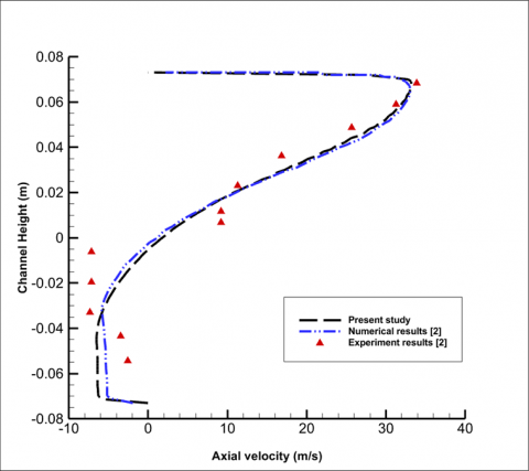
Figure 4 compares our findings to those of Demartini et al. [2] at x=0.525 m and Re=87300 in terms of both experimental and numerical results. The current and past numerical results are in excellent agreement, as indicated in the figure. This comparison therefore supports our model.
Figure 4. Comparison between our results and Demartini et al. [2] at x=0.525 m and Re=87300
The velocity profiles are shown at various axial positions along the channel in this section. To explore the primary characteristics of the velocity, these locations were chosen with care. There were 7 axial locations: 0.159 and 0.189 m upstream of the first baffle, 0.525 m baffle downstream of the second, 0.255, 0.285, 0.315, and 0.345 m between the two baffles.
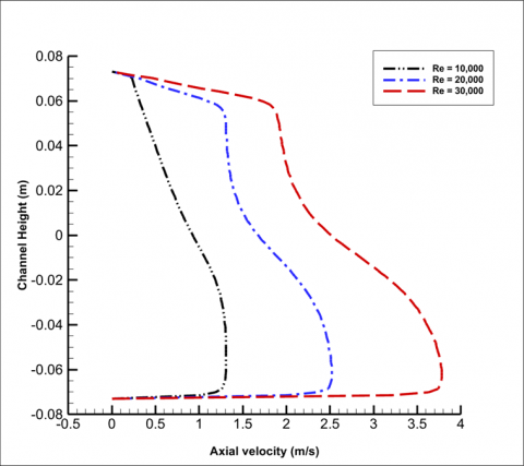
Figure 5. Axial velocity profile at Re=10,000, 20,000 and 30,000 at a location x=0.159 m
At Re=10,000, 20,000, and 30,000 at a point x=0.159 m, the variations of the axial velocity profile across the duct are shown in Figure 5. The presence of the first baffle that is located in the upper half of the channel induces a strong reduction of velocity in this region, but an increase in the flow in the lower half of the channel especially in the vicinity of the passage under the baffle. For a variety of Reynolds number values, the axial velocity profiles are essentially the same. With rising Reynolds number, the axial velocity profile's slope decreases.
Figure 6 depicts the changes in the axial velocity profile across the channel at Re=10,000, 20,000, and 30,000 at a position x=0.189 m. Since this site is also upstream of the first baffle, the profiles of axial velocity are virtually identical for various Reynolds numbers. The maximum value of the axial velocity increased by roughly 17% compared to the point x=0.159 m. The axial velocity profile's slope was less steep than it was in the scenario where x=0.159 m.
Figure 6. Axial velocity profile at Re=10,000, 20,000 and 30,000 at a location x=0.189 m
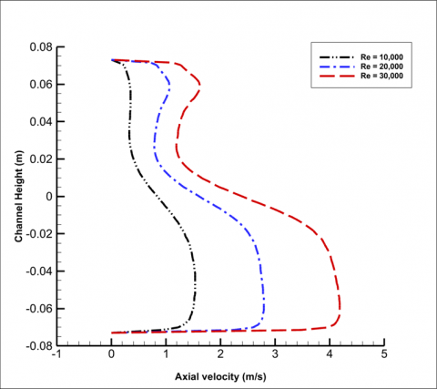
Figure 7. Axial velocity profile at Re=10,000, 20,000 and 30,000 at a location x=0.255 m
The profiles of axial velocity over the channel at Re=10,000, 20,000, and 30,000 is shown in Figure 7 at x=0.255 m. Low velocities exhibit negative values near the top wall and just next to the top baffle at x=0.255. This is a result of recirculation brought on by high pressure values in certain places. An indication that a vortex is present in the area is the development of negative axial velocity measurements. The axial velocity is zero in the center of the channel, yet it nonetheless reached its highest value close to the bottom wall of the duct.
The profiles of axial velocity over the channel at Re=10,000, 20,000, and 30,000 are shown in Figures 8, 9, and 10 at sites where x=0.285, 0.315, and 0.345 m, respectively. These values are all situated in the space between the two baffles.
The pressure drops as one approaches the bottom baffle, and the axial velocity across the duct had no negative values. At x=0.285, 0.315, and 0.345 m, respectively, the maximum value of the axial velocity fell by roughly 5%, 18%, and 41% from those values at x=0.255 m.
Figure 8 shows a residual effect of the first baffles on the velocity distribution. We noticed that there is still some region of recirculation although the values of velocities are all positive at different height of the channel. The minimum values of velocities are found near the middle axis of the channel. This axial velocity profile at this location is in an excellent agreement with Figure 3(c) [4].
Figure 8. Axial velocity profile at Re=10,000, 20,000 and 30,000 at a location x=0.285 m
Figure 9. Axial velocity profile at Re=10,000, 20,000 and 30,000 at a location x=0.315 m
At Re=10,000, 20,000, and 30,000 at a point x=0.315 m, the variations of the axial velocity profile across the duct are shown in Figure 9. As we move downstream from the first baffle, the velocity profiles are getting more smooth compared with those in Figure 8. That indicates a reduction in the recirculation zone.
Figure 10 shows the variations of the axial velocity profile across the duct at a point where x=0.345 m. This location is very close from the second baffle where the effect of the first one is minimal. The velocity profiles are more uniform specially in the bottom half of the channel.
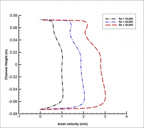
Figure 11 shows the changes in the axial velocity profile across the channel at Re=10,000, 20,000, and 30,000 at a site downstream of the bottom baffle (x=0.525 m). The bottom baffle's presence drove the flow toward the upper gap at faster speeds toward the channel's outlet, where the stream separation occurred, creating a sizable vortex on its backside.
Figure 10. Axial velocity profile at Re=10,000, 20,000 and 30,000 at a location x=0.345 m
Figure 11. Axial velocity profile at Re=10,000, 20,000 and 30,000 at a location x=0.525 m
The contour plots for the axial velocity fields along the channel at Re=10,000, 20,000, and 30,000 are shown in Figure 12. It is observed that by raising the inflow velocity, the axial velocity values rise at any point along the channel. The distance between the baffles and the space between the nozzles for each baffle affect the length of the recirculation region. Above the second baffle at Re=30,000, there is a wide zone with extremely great flow velocities already present. Furthermore, we discovered that the top wall of the duct, where the bottom baffle plate is positioned, and the nozzle exits are where the largest velocity is found. Just downstream of the two baffles, at the top and bottom of each baffle, negative velocities are seen. Additionally, there are recycling cells behind each trapezoidal segment.
The main purpose of design the perforated baffles with nozzles is to generate local vortex generation just behind the baffles. Nozzle shapes with enhance the dynamic flow in the channel and this clearly shown in Figure 12. The dynamic performance was improved by increasing values of the Reynolds number.
Figure 12. Axial velocity field at Re= (a) 10,000, (b) 20,000 and (c) 30,000 along the channel
Figure 13. Vertical velocity field at Re= (a) 10,000, (b) 20,000 and (c) 30,000 along the channel
Figure 13 displays the contour plots for the vertical velocity fields along the channel at Re=10,000, 20,000, and 30,000. Near the center of the channel, a zone with negative velocities was produced by the top baffle's effect. By raising the Reynolds number, the recirculation region's length is extended. Just upstream of the second baffle is where the zone of greatest vertical velocities may be seen. Additionally, it is clear from this picture that a sizeable area is prone to rapid flow close to each baffle's lower nozzles. The values of maximum and negative vertical velocities are lower than those of axial velocity in comparison to the contours of axial velocity.
Figure 14. Coefficient of skin friction along the upper wall at Re=10,000, 20,000 and 30,000
Figure 14 shows how the Reynold number affects the values of skin friction coefficient. According to the findings, decreasing skin friction values increased the channel's thermal enhancement factor by decreasing skin friction values. The region near the duct’s outlet had the highest value of the coefficient of skin friction, and the area directly downstream of the top baffle had the lowest value. The first baffle, which is situated at the top wall of the duct, greatly reduces the coefficient of skin friction at the channel intake. In this situation, the air has the chance to move toward the bottom wall of the channel. As a result, there is little air contact with the upper surface of the duct. As seen in the image, the coefficient of skin friction is once much higher at the regions matching to the flow recirculation areas. We have the same trend comparing with Figure 15 [13]. As we notice, in the channel length between 0.2 and 0.3 m, the values of the skin friction coefficient are decreased then increased and decreased again. This is due the growing fields of the velocity and turbulence.
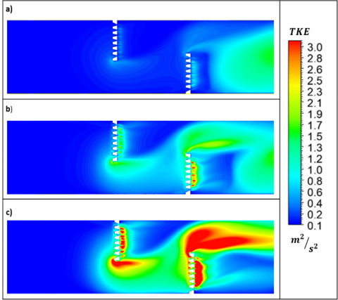
There are three zones in Figure 15 that illustrate how the turbulent kinetic energy (TKE) increases as the Reynolds number rises: zone one, between the entrance and the first baffle, where the turbulence is less significant with a nearly constant value; zone two, between the two baffles, where the turbulent kinetic energy reaches its maximum value of about 3 m2s2 at the bottom of the top baffle and also at nozzle exits; and zone three, between the two baffles. The turbulent kinetic energy was enhanced with increasing values of the Reynolds number, and accordingly, Reynolds number of 30,000 provides the maximum values of turbulent kinetic energy. The trend of the turbulent kinetic energy shown here is in good agreement with the trend of Menni et al. [13], Figure 9.
Figure 15. Turbulent kinetic energy at Re= (a) 10,000, (b) 20,000 and (c) 30,000 along the channel
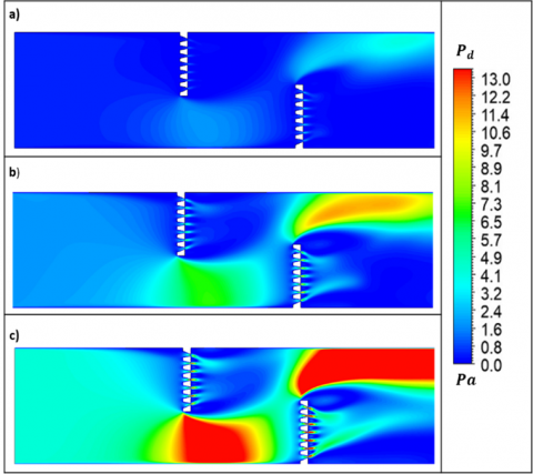
Figure 16. Dynamic pressure at Re= (a) 10,000, (b) 20,000 and (c) 30,000 along the channel
Figure 16 displays the dynamics pressure (Pd) along the channel for Re=(a) 10,000, (b) 20,000, and (c) 30,000. Due to the existence of recirculation cells, as shown in the picture, the pressure values are extremely low close to the top baffle, particularly in the upstream region.
The pressure values are higher where the upper surfaces of the baffles meet the inner surfaces of the duct. Near the upper surface of the airway, close to the channel outflow, the dynamic pressure is at its highest. Due to the fast airflow in these areas, it also has excellent values towards the upper left side of the bottom baffle. The image also demonstrates how the dynamic pressure value tends to increase as Reynolds number values increase. The dynamic pressure values fit the turbulent kinetic energy trend as depicted in Figure 15 quite well.
Comparing with Figure 12 which displays the axial velocity field, there is excellent agreement in the trend of dynamic pressure. As seen, the areas of high velocities in underneath the first baffle and above the second one have also high values of dynamic pressure. Also in the downstream regions of both baffles, the corresponding values of both axial velocities and dynamics pressures are having the same trend.
To investigate a turbulent air flow via a channel, a numerical simulation was run. In order to enhance the mixture and to improve the transfer of heat, two perforated nozzle-shaped vertical baffles were added to the field at the top and bottom surfaces of the duct. In this model, two vertical baffles in the shape of perforated nozzles with eight trapezoidal portions each forming seven nozzles are used. The top and bottom sides of the ducts’ walls are the places to these two vertical baffles.
The experimental data of Demartini et al. [2] at Re=87300 and at a location of 0.525 m were used to validate the numerical results, and the comparison showed excellent agreement. The findings were used to assess the low Reynolds number k-model's predictions of the turbulent flow's dynamic behavior. The range of the Reynolds number was 10,000-30,000,000.
Axial velocities are distributed in profiles, with the highest values occurring through the nozzles, above the bottom baffle, and below the top baffle. There are numerous recirculation zones spread throughout various areas. These areas were discovered behind each trapezoidal part, as well as above and beneath both baffles.
The greatest values for the vertical velocities are positioned upstream of the bottom baffle and happen at Re=30000. A significant recirculation zone is present immediately upstream of the top baffle.
The findings demonstrated that lowering skin friction levels as the Reynolds number increases improves the channel's thermal enhancement factor.
The pressure values rise where the inner walls of the duct meet the upper surfaces of the baffles.
Depending on the Reynolds number, there are three zones that characterize the turbulent kinetic energy. Zone 1, which is situated in between the entry and the first baffle, is less affected by the turbulence. The turbulent kinetic energy in zone two, between the two baffles, reaches its peak value of roughly 3 m2s2 near the bottom of the top baffle as well as at the nozzle exits. The highest rate of the turbulent kinetic energy occurs in zone three, which is situated between the second baffle and the channel's exit, at Reynolds number 30,000.
Based on the results we have, the current design of the perforated nozzle-shaped baffles may affect the design of heat exchangers to be more efficient.
Finally, a number of further future studies have to be taken into consideration based on the current numerical simulation analysis. These include, but are not limited to the following. (1) Change the baffles' shape by using inclined baffles instead of straight ones, or having different perforation shapes such as a cone style. (2) Alter the baffles' nozzle dimensions so that we may increase the number of nozzles for the same baffle’s dimensions or keeping the same number of nozzles but changing the inlet and exit dimensions. (3) Add more baffles instead of just 2 perforated baffles at the top and bottom of the channel’s walls as we have done in this study. (4) Add a thermal analysis by introducing the energy equation and several thermal boundary conditions. All of the above suggestions could be used to establish the channel's ideal geometry parameters.
|
u |
fluid velocity in x-direction, m/s |
|
v |
fluid velocity in y-direction, m/s |
|
ρ |
density, kg/m3 |
|
P |
static pressure, Pa |
|
$\mu_l$ |
molecular viscosity, Pa.s |
|
$\mu_t$ |
turbulent viscosity, Pa.s |
|
$\tau_w$ |
shear stress at the wall, N/m2 |
|
$D_h$ |
hydraulic diameter, m |
|
$c_\mu$ |
turbulent constant |
|
$\sigma_k$ |
turbulent constant |
|
$\varepsilon_k$ |
turbulent constant |
|
$G_{1 \varepsilon}$ |
turbulent constant |
|
$G_{2 \varepsilon}$ |
turbulent constant |
|
$C_f$ |
skin friction coefficient |
[1] Berner, C., Durst, F., McEligot, D.M. (1984). Flow around baffles. ASME Journal of Heat Transfer, 106(4): 743-749. https://doi.org/10.1115/1.3246747
[2] Demartini, L.C., Vielmo, H.A., Möller, S.V. (2004). Numeric and experimental analysis of the turbulent flow through a channel with baffle plates. Journal of the Brazilian Society of Mechanical Sciences and Engineering, 26(2): 153-159. https://doi.org/10.1590/S1678-58782004000200006
[3] Benzenine, H., Saim, R., Abboudi, S., Imine, O. (2013). Numerical analysis of a turbulent flow in a channel provided with transversal waved baffles. Thermal Science, 17(3): 801-812. https://doi.org/10.2298/TSCI111004099B
[4] Jamil, M.M., Adamu, M.I., Ibrahim, T.R., Hashim, G.A. (2015). Numerical study of separation length of flow through rectangular channel with baffle plates. Journal of Advanced Research Design, 7(1): 19-33.
[5] El-Said, E.M. (2020). Numerical investigations of fluid flow and heat transfer characteristics in solar air collector with curved perforated baffles. Engineering Reports, 2(4): e12142. https://doi.org/10.1002/eng2.12142
[6] Benosman, F., Amraoui, M.A. (2021). Study of air flow in a solar collector equipped with two inclined obstacles. E3S Web of Conferences, 321: 04015. https://doi.org/10.1051/e3sconf/202132104015
[7] Menni, Y., Lorenzini, G., Kumar, R., Mosavati, B., Nekoonam, S. (2021). Aerodynamic fields inside S-shaped baffled-channel air-heat exchangers. Mathematical Problems in Engineering, 2021: 1-11. https://doi.org/10.1155/2021/6648403
[8] Salmi, M., Afif, B., Akgul, A., Jarrar, R., Shanak, H., Menni, Y., Ahmad, H., Asad, J. (2022). Turbulent flows around rectangular and triangular turbulators in baffled channels: A computational analysis. Thermal Science, 26(Suppl 1): S191-S199. https://doi.org/10.2298/TSCI22S1191S
[9] Mahdi, K., Bekrentchir, K., Hussein, A. K., Akgul, A., Shanak, H., Asad, J., Akkurt, N., Menni, Y. (2022). Using obstacle perforation, reconfiguration, and inclination techniques to enhance the dynamic and thermal structure of a top-entry channel. Thermal Science, 26(Suppl 1): S475-S484. https://doi.org/10.2298/TSCI22S1475M
[10] Menni, Y., Ghazvini, M., Ameur, H., Kim, M., Ahmadi, M.H., Sharifpur, M. (2020). Combination of baffling technique and high-thermal conductivity fluids to enhance the overall performances of solar channels. Engineering with Computers, 38(Suppl 1): 607-628. https://doi.org/10.1007/s00366-020-01165-x
[11] Boonloi, A., Jedsadaratanachai, W. (2021). Heat transfer potentiality and flow behavior in a square duct fitted with double-inclined baffles: A numerical analysis. Modelling and Simulation in Engineering, 2021: 1-15. https://doi.org/10.1155/2021/9957126
[12] Razavi, S.E., Adibi, T., Faramarzi, S. (2020). Impact of inclined and perforated baffles on the laminar thermo-flow behavior in rectangular channels. SN Applied Sciences, 2: 1-9. https://doi.org/10.1007/s42452-020-2078-8
[13] Menni, Y., Azzi, A., Chamkha, A., Harmand, S. (2019). Analysis of fluid dynamics and heat transfer in a rectangular duct with staggered baffles. Journal of Applied and Computational Mechanics, 5(2): 231-248. https://dx.doi.org/10.22055/jacm.2018.26023.1305
[14] Ameur, H., Sahel, D., Menni, Y. (2021). Numerical investigation of the performance of perforated baffles in a plate-fin heat exchanger. Thermal Science, 25(5 Part B): 3629-3641. https://doi.org/10.2298/TSCI190316090A
[15] Liang, C.H., Feng, C.N., Lei, T.Y., Li, Z.X. (2019). Numerical studies on the effect of baffle on the heat transfer and flow in cross-corrugated triangular ducts. IOP Conference Series: Earth and Environmental Science, 238: 012086. https://doi.org/10.1088/1755-1315/238/1/012086
[16] Krishna Putra, A.B., Ahn, S.W. (2008). Heat transfer and friction behaviour in a channel with an inclined perforated baffle. International Journal of Air-Conditioning and Refrigeration, 16(2): 70-76.
[17] Ameur, H. (2020). Effect of corrugated baffles on the flow and thermal fields in a channel heat exchanger. Journal of Applied and Computational Mechanics, 6(2): 209-218. https://doi.org/10.22055/JACM.2019.28936.1521
[18] Dutta, P., Dutta, S. (1998). Effect of baffle size, perforation, and orientation on internal heat transfer enhancement. International Journal of Heat and Mass Transfer, 41(19): 3005-3013. https://doi.org/10.1016/S0017-9310(98)00016-7
[19] Eiamsa-ard, S., Pattanapipat, S., Promvonge, P. (2013). Influence of triangular wavy baffles on heat and fluid flow characteristics in a channel. Journal of Mechanical Science and Technology, 27: 2199-2208. https://doi.org/10.1007/s12206-013-0534-8