Abhishek Agarwal*![]() | Rafael C. Batista
| Rafael C. Batista![]()
© 2023 IIETA. This article is published by IIETA and is licensed under the CC BY 4.0 license (http://creativecommons.org/licenses/by/4.0/).
OPEN ACCESS
In heavy-duty vehicles, Exhaust Gas Recirculation (EGR) coolers have been used since 2002 to reduce NOx emissions by recirculating exhaust gases. EGR systems increase fuel efficiency and achieve more thorough combustion, while the EGR cooler, which cools the exhaust gases, is crucial to protect the engine by lowering the combustion temperature. This research evaluates the flow behavior and thermal characteristics of EGR coolers using the k-omega turbulence model. The study compares the effectiveness of two designs of EGR coolers: the single coolant inlet type and the four-inlet type configuration. The CAD design of the EGR cooler is developed in Creo design software, and CFD simulations are conducted using the ANSYS CFX simulation package. The results show that the incorporation of additional coolant inlet tubes improves the EGR cooler's performance. The four-inlet design exhibits higher effectiveness compared to the single-inlet design at every operating temperature. The effectiveness is maximum at an operating temperature of 691K, and the four-inlet design shows 0.02 higher effectiveness than the single-inlet design at an operating temperature of 1058K. The conventional design of the EGR cooler with a single coolant inlet can be substituted with the new proposed design of the EGR cooler with four coolant inlets. The new proposed design of the EGR cooler has higher effectiveness and would enable the reduction of NOx emissions and improve engine efficiency.
Exhaust Gas Recirculation system, EGR cooler, CFD simulations, four-inlet configuration, thermal characteristics, fuel efficiency, heavy-duty vehicles, NOx emission
An Exhaust Gas Recirculation (EGR) cooler is an essential component in modern diesel engines. It is a heat exchanger that cools the exhaust gas recirculated back into the engine cylinders. The EGR system works by recirculating some of the exhaust gases back into the engine, which helps to reduce nitrogen oxide (NOx) emissions. The EGR system lowers the combustion temperature by reducing the amount of oxygen in the combustion chamber. The reduction in oxygen leads to incomplete combustion, resulting in reduced NOx formation. The cooled recirculated gases also help to prevent engine knocking and reduce engine wear and tear [1]. The EGR cooler is typically a shell and tube heat exchanger that exchanges heat between the hot exhaust gases and the cooling fluid. The cooling fluid used can be water, glycol, or air. The EGR cooler is positioned between the exhaust manifold and the EGR valve, which controls the amount of recirculated exhaust gas. The design of the EGR cooler is critical to its efficiency. The EGR cooler should be able to handle high temperatures and pressure, and it should be able to withstand corrosive exhaust gases. The cooling fluid should be able to absorb enough heat from the exhaust gas to cool it to the required temperature. The EGR cooler should also be designed to minimize pressure drop, which can affect engine performance [2, 3]. Reducing NOx emissions in heavy-duty vehicles is of utmost importance for safeguarding the environment and public health. A critical component in achieving this objective is the implementation of efficient EGR coolers, which actively contribute to lowering combustion temperatures, enhancing combustion control, and optimizing thermal efficiency. By equipping heavy-duty vehicles with EGR systems featuring effective coolers, a significant reduction in NOx emissions can be achieved, thereby enabling compliance with stringent emission standards and ensuring a cleaner future. The conventional design of EGR coolers, with a single coolant entry, presents certain limitations such as non-uniform flow and limited heat transfer capacity. To address these challenges, the integration of multiple coolant entries holds immense potential. This innovative approach enhances the heat transfer capability of EGR coolers by fostering a uniform flow distribution across the lateral direction of the cooler. By promoting uniform flow, the multiple coolant entry design allows for improved heat transfer efficiency, effectively mitigating the limitations of the conventional design.
By embracing the concept of multiple coolant entries, heavy-duty vehicles can unlock significant benefits. Enhanced heat transfer capability leads to better cooling of exhaust gases, ultimately resulting in improved combustion control and increased thermal efficiency. This transformative approach not only reduces NOx emissions but also boosts the overall performance and sustainability of heavy-duty vehicles.
In conclusion, the integration of multiple coolant entries in EGR coolers represents a groundbreaking advancement in emission reduction technology for heavy-duty vehicles. By addressing the limitations of the conventional design and enabling uniform flow distribution, this innovative approach enhances heat transfer capacity and contributes to achieving stringent emission standards. By adopting such cutting-edge solutions, heavy-duty vehicles can play a pivotal role in preserving the environment, safeguarding public health, and embracing a cleaner and greener future.
Abarham et al. [4] investigated the performance of an automotive EGR cooler with offset strip fins through experimental and numerical methods. The authors found that the offset strip fins significantly increased the heat transfer coefficient and thermal performance of the EGR cooler. The numerical simulations also revealed that the pressure drop across the EGR cooler decreased with increasing Reynolds number.
Kern et al. [5] compared the thermal performance of three different types of EGR coolers for heavy-duty diesel engines: tube-and-fin, stacked-plate, and printed-circuit heat exchangers. The authors found that the printed-circuit heat exchanger had the highest thermal performance, followed by the stacked-plate and tube-and-fin heat exchangers. The authors also noted that the pressure drop across the EGR cooler increased with increasing thermal performance.
Reza Razmavar et al. [6] investigated the effects of fouling on the performance of an EGR cooler through experimental and numerical methods. The authors found that fouling significantly reduced the heat transfer coefficient and thermal performance of the EGR cooler. The numerical simulations also revealed that the fouling layer created a thermal resistance that decreased the effectiveness of the EGR cooler. The authors concluded that regular maintenance and cleaning of the EGR cooler is necessary to prevent fouling and maintain optimal engine performance.
Sul et al. [7] reviews the fouling mechanism of EGR coolers in diesel engines and the effects of fouling on engine performance. The authors found that fouling can cause a decrease in engine efficiency and increase emissions. They also found that the type of fouling and severity can vary depending on engine operating conditions and the type of fuel used. Xu et al. [8] experimentally investigated the performance of a compact heat exchanger used as an EGR cooler in a diesel engine. The authors found that the heat exchanger design significantly affected the cooling performance and pressure drop of the EGR cooler.
They also found that increasing the coolant flow rate can improve the cooling efficiency, but also increase the pressure drop. Nagendra et al. [9] presents a numerical simulation of the effect of EGR cooler fouling on engine performance and emissions. The authors found that fouling can cause a decrease in engine power and an increase in emissions. They also found that the severity of fouling and the type of fouling can have different effects on engine performance and emissions.
Yang et al. [10] presents an optimal design of an EGR cooler for a diesel engine based on thermodynamic analysis and computational fluid dynamics simulation. The authors found that the optimal design can significantly improve the cooling performance and reduce pressure drop compared to the baseline design. They also found that the optimal design can reduce engine NOx emissions by up to 12%.
The objective of the current study is to evaluate the flow behavior and thermal characteristics of the EGR cooler using the k omega turbulence model. The design configuration investigated in the current research is of single coolant inlet type and four inlet type configurations. The CAD design of the EGR cooler is developed in Creo design software and CFD simulation is conducted using the ANSYS CFX simulation package.
The methodology steps involve different stages i.e., modeling, meshing, boundary conditions, solution stage, and post-processing [11]. The CAD model of the EGR cooler is developed in 3D parametric Creo design software. The design included shell, air inlet tubes, and coolant inlet and outlet tubes. The Dimensions of the EGR cooler are provided in Table 1. The developed model of the EGR cooler is shown in Figures 1 and 2 respectively. The design comprises of shell, tube, and baffles.
Table 1. Dimensions of EGR cooler
|
Number of Tubes |
28 |
|
Number of Baffles |
4 |
|
Tube Length |
220mm |
|
Total Length |
296mm |
|
Material |
Stainless steel |
Figure 1. CAD design of EGR cooler in a solid shade
Figure 2. CAD design of EGR cooler in the wireframe model
The design of the EGR cooler is imported into the design modeler of the ANSYS simulation package. The model is checked for geometric imperfections, edge imperfections, and other defects. The imported design of the EGR cooler is shown in Figure 3.
The model of the EGR cooler is discretized. The discretization process is based on topological characteristics, and geometry type [12]. The mesh can be structured or unstructured type.
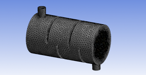
The meshing is of the fine type which enables to capture of all the important features of the flow, such as boundary layers and turbulence [13]. The number of elements generated is 1525532 and the number of nodes generated is 586244. The meshed model is shown in Figure 4.
Figure 3. Imported design of EGR cooler
Figure 4. Meshed design of EGR cooler
Figure 5. Domain definition of EGR cooler
The subsequent step is domain definition for both fluids i.e., coolant and flue gases. The domain type defined for flue gases is fluid type. The fluid material type is NO and the reference pressure is set to 1atm. The domain definition of the shell is shown in Figure 5.
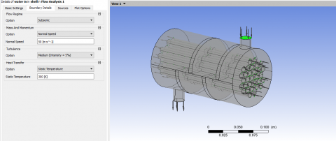
The domain is defined for coolant. The domain type is set to water with a reference pressure of 1atm. The buoyancy model is set to non-buoyant and the initial domain motion is set to stationary. The water inlet and water outlet boundary condition are defined for the EGR cooler.
Figure 6. Water Inlet boundary condition of EGR cooler
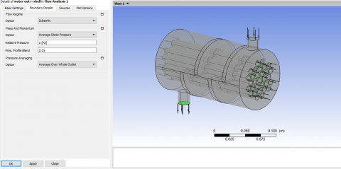
The water inlet boundary conditions are defined with an inlet velocity of 50m/s and at 300K as shown in Figure 6. The outlet boundary conditions are defined for water. The relative outlet pressure is set to 0 as no pump is used. The water outlet boundary condition is shown in Figure 7.
Figure 7. Water outlet boundary condition of EGR cooler
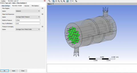
Figure 8. Flue gas inlet boundary condition of EGR cooler
Figure 9. Flue gas outlet boundary condition of EGR cooler
The flue gas inlet and outlet boundary condition are defined for the EGR cooler. The flue gas inlet boundary condition includes a mass flow rate of .05Kg/s and the flue gas outlet boundary condition are defined with 0 relative pressure as shown in Figures 8 and 9 respectively. The k omega turbulence model is used for the simulation. The k omega turbulence model is shown below. The k-omega model performs better than the k-epsilon model in predicting separated flows, such as flows over bluff bodies, and other complex geometries. The k-omega model has a built-in mechanism that helps account for the effects of adverse pressure gradients and streamline curvature, enabling it to provide more reliable predictions for these types of flows.
$\frac{\partial}{\partial t}(\rho . k)+\vec{\nabla} \cdot(\rho . \vec{u} . k)=\vec{\nabla} \cdot\left(\rho .\left\{v_l+\frac{v_t}{\sigma_{t, k}}\right\} \cdot \vec{\nabla} k\right)+\rho .\left(P_K-\varepsilon\right)$
$\begin{gathered}\frac{\partial}{\partial t}(\rho.w)+\vec{\nabla} \cdot(\rho.\vec{u}.w)=\vec{\nabla} \cdot\left(\rho .\left\{v_l+\frac{v_t}{\sigma_w}\right\} \cdot \vec{\nabla} w\right)+\rho.w.\left(\gamma \cdot \frac{P_k}{k}-\right.\beta.w)+2.\left(1-F_1\right).\left\{\rho.\frac{\sigma_{w 2}}{w}\right\} \cdot \vec{\nabla} k\vec{\nabla} w\end{gathered}$
After defining inlet and outlet boundary conditions, the solver settings are defined. The solver settings include RMS residual settings, interpolation schemes, and precision settings [14]. The CFD simulation is run to determine and convergence criteria are attained as per .0001 RMS residual values.
From the CFD simulation, the temperature distribution plot, pressure distribution plot, and velocity distribution plot are obtained.
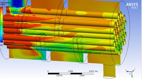
Figure 10. Temperature plot of single water inlet tube design
From the temperature distribution plot (Figure 10) across the mid-section plane, it is evident that the temperature is maximum near the flue gas inlet region. The maximum temperature obtained from the analysis is 708.9 K. Table 2 shows the grid independence test.
Table 2. Grid independence test
|
Number of Elements |
Temperature Magnitude (K) |
|
1525532 |
708.88 |
|
1525598 |
708.87 |
|
1525655 |
708.86 |
|
1525687 |
708.89 |
|
1525692 |
708.9 |
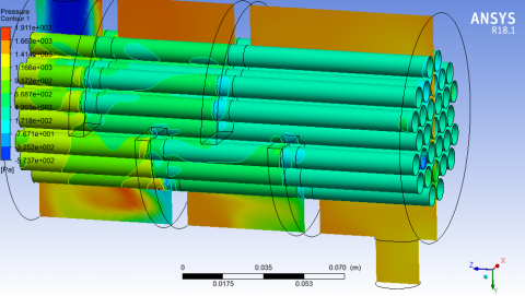
Figure 11. Pressure plot of single water inlet tube design
The temperature of flue gas reduces along the length of the tube and reaches to minimal towards end of the tube.
The pressure distribution plot is obtained across mid-section plane as shown in Figure 11. The pressure is higher near the flue gas inlet and reduces along the length of the tube. The pressure magnitude is also higher for coolant (water) and reduces towards the exit of the shell.
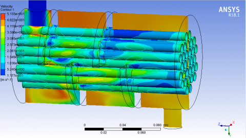
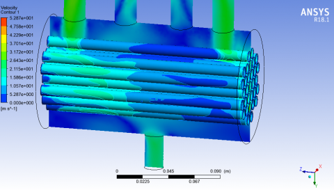
Figure 12. Velocity plot of single water inlet tube design
The velocity distribution plot is obtained across mid-section plane and along the tube as presented in Figure 12. The velocity is higher near the gas inlet zone and coolant (water) inlet zone. The velocity is higher at the center of the tube with a magnitude of 35.98m/s. The velocity profile regime is non-uniform due to turbulence. The velocity of the exhaust gas outlet is 12.28m/s which is in close agreement with the velocity in literature [15] which validates the result.
Figure 13. Temperature plot of EGR cooler with 4 coolant inlet
Figure 14. Pressure plot of EGR cooler with 4 coolant inlet
The temperature distribution plot across mid-section plane of the EGR cooler with 4 coolant inlet is shown in Figure 13. The temperature distribution shows a higher value at the side tubes and is lower at the center tubes which are in-line arrangement with coolant inlet tubes.
The pressure distribution plot is obtained across mid-section plane of the EGR cooler with 4 coolant inlet as shown in Figure 14. The pressure magnitude is uniform for flue gas tubes. For the water tube, the pressure is higher at the 1st tube and 4th tube as shown in green colored contour with a magnitude of 7.98Pa. The pressure at the outlet is 3.02Pa.
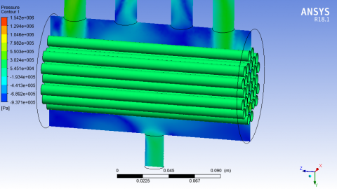
Figure 15. Velocity plot of EGR cooler with 4 coolant inlet
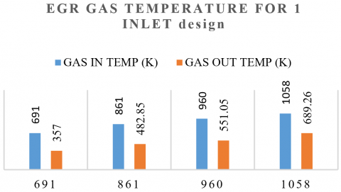
The velocity distribution plot is obtained for the EGR cooler with 4 coolant inlet as shown in Figure 15. The velocity plot shows a higher magnitude at the 1st and 4th coolant inlet tube. The velocity at the inlet zone is nearly 31.7m/s. The velocity at the outlet zone of coolant is 13.7m/s. Table 3 and 4 show the temperature values for design 1 and 2 respectively while Figure 16 and 17 show the temperature comparison for both designs respectively.
Table 3. Temperature table for design 1
|
Gas in Temp (k) |
691 |
861 |
960 |
1058 |
|
Gas out temp (k) |
357 |
482.85 |
551.05 |
689.26 |
|
Coolant in temp (k) |
341 |
341 |
341 |
341 |
|
Coolant out temp (k) |
350 |
352.5 |
353 |
350 |
Figure 16. Gas temperature plot for design 1
Figure 17. Gas temperature plot for design 2
Table 4. Temperature table for design 2
|
Gas In Temp |
692 |
861 |
960 |
1058 |
|
Gas Out Temp |
348 |
464 |
538 |
678 |
|
Coolant In Temp |
341 |
341 |
341 |
341 |
|
Coolant Out Temp |
354 |
356 |
354 |
351 |
Effectiveness is a very important parameter for the design of a heat exchanger. The effectiveness of the EGR cooler is given by the following:
Effectiveness = Ehin – Egout / Ehin – Ecin
Ehin is hot gas inlet temperature in K
Egout is the hot gas outlet temperature in K
Ecin is hot gas inlet temperature in K
The effectiveness is calculated for both designs i.e., single coolant inlet and multiple coolant inlet designs. The effectiveness comparison is shown in Figure 18.
Figure 18. Effectiveness comparison between both designs
The effectiveness comparison chart shows higher effectiveness value for EGR cooler with 4 coolant inlet designs as compared to single inlet coolant design.
The research findings highlight the remarkable effectiveness of employing CFD simulation and the k-omega turbulence model to assess the flow behavior and thermal characteristics of EGR coolers. By incorporating additional coolant inlet tubes, the performance of the EGR cooler is significantly enhanced, with the four-inlet design consistently surpassing the single-inlet design across various operating temperatures. Particularly noteworthy is the four-inlet design's remarkable 0.02 higher effectiveness compared to the single-inlet design at an operating temperature of 1058K, while the pinnacle of effectiveness is achieved at 691K.
Nevertheless, it is crucial to recognize the limitations inherent in this study. Firstly, the evaluation relied on computational simulations, which, while providing invaluable insights, may not entirely encapsulate the intricacies and diversities of real-world scenarios. Furthermore, the analysis predominantly centered on flow behavior and thermal characteristics, overlooking other factors like mechanical stresses or material properties, which can profoundly impact the overall performance of the EGR cooler. To comprehensively evaluate these aspects, future research should aim to integrate them into the analysis.
Looking ahead, the future of EGR cooler design holds tremendous potential in terms of integration with other emission control systems, such as selective catalytic reduction (SCR) or diesel particulate filters (DPF), to create more streamlined and efficient exhaust after-treatment systems. Moreover, the leveraging of cutting-edge advancements in electronics and sensor technology presents a promising avenue for enhancing EGR cooler performance through data-driven diagnostics and optimization. By conducting simulations with higher iterations and precise convergence settings, accuracy can be heightened, and more comprehensive insights can be obtained.
The optimization of EGR cooler designs and the utilization of advanced technologies open up exciting opportunities for heavy-duty vehicles to curtail NOx emissions and enhance engine efficiency. Although the scope of these research findings is limited, they provide invaluable insights for the development of effective and sustainable emission control strategies within the automotive industry.
[1] Abarham, M., Zamankhan, P., Hoard, J.W., Styles, D., Sluder, C.S., Storey, J.M., Lance, M.J., Assanis, D. (2013). CFD analysis of particle transport in axi-symmetric tube flows under the influence of thermophoretic force. International Journal of Heat and Mass Transfer, 61: 94-105. https://doi.org/10.1016/j.ijheatmasstransfer.2013.01.071
[2] Paz, C., Suárez, E., Vence, J., Cabarcos, A. (2020). Fouling evolution on ribbed surfaces under EGR dry soot conditions: Experimental measurements and 3D model validation. International Journal of Thermal Sciences, 151: 106271. https://doi.org/10.1016/j.ijthermalsci.2020.106271
[3] Paz, C., Suárez, E., Conde, M., Vence, J. (2020). Development of a computational fluid dynamics model for predicting fouling process using dynamic mesh model. Heat Transfer Engineering, 41(2): 199-207. https://doi.org/10.1080/01457632.2018.1522108
[4] Abarham, M., Hoard, J., Assanis, D., Styles, D., Curtis, E.W., Ramesh, N., Sluder, C.S., Storey, J. M. (2009). Modeling of thermophoretic soot deposition and hydrocarbon condensation in EGR coolers. SAE International Journal of Fuels and Lubricants, 2(1): 921-931. https://doi.org/10.4271/2009-01-1939
[5] Kern, D. (1959). A theoretical analysis of thermal surface fouling. Br. Chem. Eng., 4: 258-262.
[6] Reza Razmavar, A., Reza Malayeri, M. (2016). A simplified model for deposition and removal of soot particles in an exhaust gas recirculation cooler. Journal of Engineering for Gas Turbines and Power, 138(1): 011505. https://doi.org/10.1115/1.4031180
[7] Sul, H., Han, T., Bieniek, M., Hoard, J., Kuan, C.K., Styles, D. (2016). The effects of temperature, shear stress, and deposit thickness on EGR cooler fouling removal mechanism-part 2. SAE International Journal of Materials and Manufacturing, 9(2): 245-253. https://doi.org/10.4271/2016-01-0186
[8] Xu, Z., Sun, A., Han, Z., Yu, X., Zhang, Y. (2019). Simulation of particle deposition in a plate-fin heat exchanger using a particle deposition model with a random function method. Powder Technology, 355: 145-156. https://doi.org/10.1016/j.powtec.2019.07.031
[9] Nagendra, K., Tafti, D.K., Viswanathan, A.K. (2011). Modeling of soot deposition in wavy-fin exhaust gas recirculator coolers. International Journal of Heat and Mass Transfer, 54(7-8): 1671-1681. https://doi.org/10.1016/j.ijheatmasstransfer.2010.10.033
[10] Yang, B.J., Mao, S., Altin, O., Feng, Z.G., Michaelides, E.E. (2011). Condensation analysis of exhaust gas recirculation system for heavy-duty trucks. Journal of Thermal Science and Engineering Applications, 3(4): 041007. https://doi.org/10.1115/1.4004745
[11] Agarwal, A., Letsatsi, M.T. (2023). Investigation of the effect of engine cylinder fin shape on heat transfer characteristics under forced convection. In: Li, X., Rashidi, M.M., Lather, R.S., Raman, R. (eds) Emerging Trends in Mechanical and Industrial Engineering. Lecture Notes in Mechanical Engineering. Springer, Singapore. https://doi.org/10.1007/978-981-19-6945-4_9
[12] Agarwal, A., Mthembu, L. (2020). CFD analysis of conical diffuser under swirl flow inlet conditions using turbulence models. Materials Today: Proceedings, 27: 1350-1355. https://doi.org/10.1016/j.matpr.2020.02.621
[13] Agarwal, A. (2021). Modelling & numerical investigation of the effectiveness of plate heat exchanger for cooling engine oil using ANSYS CFX. International Journal of Heat and Technology, 39(2): 653-658. https://doi.org/10.18280/ijht.390237
[14] Agarwal, A., Mthembu, L. (2023). Finite element investigation of the vibration characteristics of francis turbine vanes. In: Li, X., Rashidi, M.M., Lather, R.S., Raman, R. (eds) Emerging Trends in Mechanical and Industrial Engineering. Lecture Notes in Mechanical Engineering. Springer, Singapore. https://doi.org/10.1007/978-981-19-6945-4_71
[15] Karanje, S.C., Bhusnoor, D.S. (2017). Design, “Modeling and CFD analysis of EGR cooler for future emission norms of diesel engine,”. In International Conference on Emanations in Modern Technology and Engineering (ICEMTE-2017), 5(3): 65-71.