Fawziea M. Hussien![]() | Atheer S. Hassoon*
| Atheer S. Hassoon*![]() | Johain J. Faraj
| Johain J. Faraj
© 2023 IIETA. This article is published by IIETA and is licensed under the CC BY 4.0 license (http://creativecommons.org/licenses/by/4.0/).
OPEN ACCESS
The present study outlines a mathematical framework for evaluating the energy and exergy efficiency of charging operations involving two distinct phase change materials (PCMs) denoted as PCM1 and PCM2, as well as various heat transfer fluids (HTF) and thermal energy storage (TES) systems. Using a phase change material (paraffin wax RT55 and lauric acid) in a concentric thermal storage system is investigated experimentally herein using a triple pipe heat exchanger (TPHX). As part of a three-pipe (TPHX) system, the innermost pipe transports water (hot water). The inside pipe of the exchanger is coated with paraffin wax, while the outer pipe is constructed of lauric acid. To this end, experiments were conducted to examine how changes in flow rates, input temperatures, and Stefan numbers (selected in response to charge situations) affect PCM's energy and exergy calculations. Energy-exergy efficiency and entropy generation were both found to be enhanced by increasing the intake flow rate and temperature. As the intake flow rate is increased from 11 L/min to 52 L/min, the complete melting time is reduced by 12%, 15.7%, and 19.09% for PCM1, while reduce by 23.25%, 24.5%, and 25% for PCM2, while as the input temperature is increased from 316 K to 328 K, the melting time is reduced by 36.2%. Also, the results show that the energy stored, energy efficiency and exergy efficiency at PCM1 is bigger than PCM2 at same flow rate. Where energy storge increase by 15% at minimum flow rate and 12.85% at maximum flow rate, the energy efficiency of PCM1 increase by 47% then PCM2 at maximum flow rate, while increase by 43% at minimum flow rate, while exergy efficiency of PCM1 increase by 9.45% then PCM2 at maximum flow rate, while increase by 8.47% minimum flow rate. Evaluating the Nusselt number and the entropy generation number can also help boost the efficiency of a thermal storage system.
triplex pipe heat exchanger (TPHX), thermal storage system, phase change material (PCM), paraffin wax, lauric acid, Entropy generation number, energy and exergy efficiency, Stefan number
The uncontrolled consumption of fossil fuels has resulted in a worldwide pollution disaster. The use of fossil fuels is decreasing while pollution levels are growing at an alarming rate. Cleaner energy production is possible through the utilization of renewable energy sources, which must be embraced if we are to meet these problems. Solar energy's huge potential makes it the frontrunner in this regard, yet the sun's rays are only accessible during the day. The ability to store energy for use even when the sun isn't out is essential [1]. The intriguing possibility of storage of thermal energy via the phase-changing materials (PCM) latent heat has caught the interest of investigators. Chemical stability, virtually isothermal recovery of heat, and high stored energy densities are the primary advantages. Electronics cooling [2, 3], cold storing [4, 5], Trombe walls [6, 7], and solar heated water [8, 9] are just a few of the many applications that make use of PCMs because of their many advantageous qualities. As a means of empirically evaluating a horizontal shell with a tube heat exchanger's ability to store thermal energy, Agyenim et al. [7] divided an individual heat transfer pipe into four tubes and used erythritol as a PCM. We compared the temperature gradients in shell and tube systems along three axes: axial, radial, and angular. The results showed a 3.5% enhancement in the axial direction of the phase change and a 2.5% enhancement in the direction of radial motion. Liu et al. [8] conducted a numerical study of the PCM melting process for RT27 (paraffin blend). By rearranging the size and number of HTF tubes inside the shell in a variety of configurations. The effects of diameter ratio and different multiple-tube numbers on heat transfer were also investigated for the arrangements under discussion. Combining dual large and small tubes with a diameter ratio of 2 accelerated the melting trend of PCM. Jesumathy et al. [9] conducted an experimental study of the effect of HTF temperature changing and mass flow rates on the melting process of a paraffin wax on a straight heat storage system comprised of two pipes. Melting rates improved by 25% for every 2℃ changes in HTF temperature at the input. Esapour et al. [10] also used RT35 as a PCM to conduct numerical research into the impact of several internal pipes on the melting process of a heat exchanger with multiple Pipes. Spilt pipes reduced PCM melting time by 29%. Data indicates heat transfer tube temperatures were changed during analysis. The HTF inlet temperature was raised from 50℃ to 60℃, reducing melting periods by 33% for both twin tube and multitube systems. Heat transfer properties of LTESS were quantitatively explored [11] utilizing staggered and parallel HTF tube topologies, paraffin as PCM, and air as HTF. The staggered tube arrangement increased melting by 57% through improving convective heat transmission. Kousha et al. [12] investigated the melting and solidifying mechanisms of a finless multipipe heat exchanger using setups with one to four tubes and a variety of HTF values. The PCM was cylinder-stored paraffin (RT-35). When four HTF tubes were utilized instead of one, the system's melting and solidification times were 43% and 50% shorter. Joybari et al. [13] compared the melting of RT-60 paraffin in one-tube and five-tube vertical heat exchangers. The multi-tube arrangement boosted convective effects, which accelerated PCM melting. Multiple tubes reduced melting times by 73.6 percent compared to a single tube system. Few multi-tube LTESS studies have employed fins. However, fins can accelerate melting in a multi-tube HTF tube configuration. Hosseini et al. [14] investigated the effects of Stefan number and fin length on LTESS efficiency. Analyzed lengths and Stefan number. The PCM melting process and system performance improved by 15.3% with a 0.38 Stefan number and 26mm fin length. Rathod and Banerjee [15] investigated the effect of vertically placed long fins using stearic acid as PCM. Melting time was 44.4% shorter with longitudinal fins. Wang et al. [16] investigated the effects of thermal, physical, and geometric aspects on horizontal sleeve tube LTESS performance using computational methods. PCM melting was examined using fin length, fin geometry, and various conductive shells. Specific fin angles. Finned LTESSs reduced PCM melting time by 49.1%. Thickness, length, and number of fins lowered PCM melting time.
The melting process of paraffin wax RT35 was studied statistically by Yang et al. [17] in a horizontal LTESS with annular fins. Changing the number of annular fins installed around the HTF tube allowed researchers to study how PCM melted. They found a 65% reduction in melting time with an optimal LTESS, which they determined to be one with 31 annular fins. Abdullateef et al. [18] investigated triplex tube LTESS numerically and experimentally utilizing paraffin RT82 as PCM. Interior-exterior triangular longitudinal fins were used to improve the thermal performance of LTESS. They looked studied PCM melting having and absent triangular-fins and found that using them cut melting time by 15%. Long [19] investigated PCM solidifying and melting in a triple-pipe system with PCM in the mid conduit, hot HTF in the outside conduit during charging, and cold HTF in the inside channel during discharge. They investigated how input temperature and mass flow rates influenced heat transfer in general. Basal and Ünal [20] used the enthalpy approaches to examine identical data and proposed that the triple connection. Because the tube design has a higher point of melting, it can be used faster than the typical twin tube version. Elbahjaoui et al. [21] show that when a triple pipe energy storage system is compared to a double tube system, the former has a higher energy storage density and a faster PCM melting rate when utilized in a solar water heater. Al-Abidi et al. [22] investigated how to liquid power desiccant air conditioning system using a triple pipe heat exchanger with PCM in the intermediate tube. They also investigated the impacts of varying the mass flow rate and experimenting with other heating tactics, such as heating only the interior tube, only the outside tube, or both. Mat and colleagues [23] investigated the triple pipe configuration with interior and exterior fins. A relationship was discovered between fin length and thickness and melting time. Once the energy storage and release characteristics of the LHTES system have been identified, its efficiency can be evaluated from both an energy and an exergy standpoint. Several energy-related evaluation indices, include energy efficiency [24, 25], energy efficiency ratio [26, 27], TES rate density [28], and heat storage ratio [29], are recommended for use in evaluating the LHTES system. Standard energy analysis ignores the efficiency of heat stored during charging. Due to its capacity to account for heat accessibility and temperature during heat transfer, exergy analysis is a useful technique for monitoring and optimizing LHTES system performance [30, 31]. LHTES should be assessed by exergy. Energy-based assessments of the LHTES system are common, while exergy-based analyses are new. Rahimi et al. [32] study latent heat thermal energy storage using paraffin wax RT35 as the PCM and water as the HTF. The largest helix (90 mm) reduced melting times by 72.6%. Limiting heat storage duration may enhance exergy efficiency. Li [33] examined melting temperatures and the quantity of heat transfer units made from two PCM storage systems (PCM1 and PCM2). The melting temperature and quantity of PCM1 and PCM2 heat transfer units effect the total exergetic efficiency, which increases by 19.0%, 53.8% when using two PCMs instead of one. Kousksou et al. [34] used estimations of energy and exergy to conduct a computational investigation of a solar system connected to an enclosed PCM TES unit. The results show that the PCM melting temperature significantly affects the system's energy and exergy efficiency. When looking into the charging process of a shell-tube Latent heat thermal energy storing, Erek and Dincer [35] came up with a novel method for evaluating energy and exergy efficiency and efficacy.
Based on the available literature, it appears that only a limited number of research studies have been conducted on the experimental assessment and exergy analysis of triple pipe heat exchangers that incorporate a phase change material, specifically paraffin wax RT55 and lauric acid.
The objective of the present investigation is to achieve a comprehensive understanding of the exergy-related aspects and exergy efficiency of the thermal system, owing to its crucial importance in diverse industrial applications. The principal objective of this study was to devise an innovative methodology for scrutinizing phase change materials (PCMs), encompassing paraffins and lactic acid, with the aim of enhancing comprehension of their thermal characteristics. The subsequent phase involves an inquiry into the correlation between the quantity of exergy dissipated and the count of entropy generations, while considering a range of crucial parameters and exergy characteristics. Experimental measurements are conducted to determine hot water flow rates, intake water temperatures, and the Stefan number associated with the melting process.
Thermodynamically, exergy is the most usable work that can be extracted from a reversible system under given conditions [36, 37]. Data from a triple heat exchanger is considered for use in an exergy study, using the corresponding energy equations that have been constructed.
The following equation is used to determine the PCM's average temperature.
$T_{P C M}=\frac{\sum_{\mathrm{i}=1}^5 \mathrm{~T}_{\mathrm{i}}}{5}$ (1)
Heat storage capacity is an important performance indicator for LHS equipment. Eq. (2) and the melting properties of PCM can be used to compute the total quantity of heat storage.
$Q_{P C M}=\dot{m}_{P C M}\left[c p_s\left(T_m-T_{i n i}\right)+\lambda L+c p_l\left(T_{P C M}-T_m\right)\right]$ (2)
where, $\dot{m}_{P C M}$ is mass flow rate, $c p_s \& c p_l$ are heat capacity of solid and liquid, $T_m$ is melting temperature, $\lambda$ is melting fraction, $L$ is latent heat and $\mathrm{t}$ is melting time.
Eq. (3) can be used to determine how much heat was transported from HTF to PCM, which is what is meant by "effective heat storage."
$Q_{H T F}=\int_0^t \dot{m}_f c p_f\left[T_{\text {in }}(t)-T_{\text {out }}(t)\right] d t$ (3)
where, $T_{\text {in }}(t)$ and $T_{\text {out }}(t)$ are the fluid's inlet and exit temperatures, $\dot{m}_f$ is the mass flow rate, and, $c p_f$ is the water specific heat capacity.
An additional important to note notion is the Reynolds number (Re), which is precisely defined as follows:
$\operatorname{Re}=\frac{\rho \mathrm{uD}_{\mathrm{in}}}{\mu}=\frac{4 \rho \dot{V}}{\pi \mathrm{D}_{\mathrm{in}} \mu}$ (4)
where, $\rho$ is density, $\dot{V}$ is volume flow rate of HTF, $\mu$ is fluid's dynamic viscosity, $\mathrm{u}$ is average fluid velocity and $D_{\text {in }}$ is HTF tube diameter.
The Nusselt number and Stefan number are two dimensionless parameters that are defined as follows:
$N u=\frac{q^{\prime \prime} D}{k \Delta T}$ (5)
$\mathrm{St}=\frac{c p_l\left(T-T_m\right)}{L}$ (6)
where, $c p_l$ is the liquid PCM's specific heat, $L$ is the PCM latent heat, and $T_m$ is melting temperature.
An evaluation of the PCM latent heat system's efficacy can be conducted by comparing the heat quantity gained by the PCM with the heat quantity supplied by the HTF.
$\eta=\frac{Q_{P C M}}{Q_{H T F}}$ (7)
The following can be expressed as an equation for the exergy balance [33]:
$\begin{gathered}\frac{d \psi_{s y s}}{d t}=\sum \dot{Q}_{C V} \cdot\left(1-\frac{T_0}{T}\right)-\sum \dot{W}_{C V}+P_0 \frac{d V}{d t}+ \\ \sum \dot{m}_i \cdot \psi_i-\sum \dot{m}_e \cdot \psi_e-T_0 \cdot \dot{S}_{g e n} .\end{gathered}$ (8)
In this study, the equation for the destruction of exergy at a certain volume of control can be written as follows:
$\psi_{\text {in }}-\psi_{\text {out }}-\psi_{\text {dest }}=\frac{d \psi_{\text {sys }}}{d t}$ (9)
in which, the exergy of a flow is denoted by the symbol and written as:
$\psi=\left(h-h_0\right)-T_0\left(s-s_0\right)+g\left(z-z_0\right)+\frac{u^2}{2}$ (10)
An alternative term for the ratio of exergy destroyed to exergy input is the entropy generation number ($N_S$). Since this is the case,
$\psi_{\text {in }}=\dot{m}_{H T F} C p_{H T F}\left\lceil\left(T_{H T F, \text { in }}-T_{H T F, \text { out }}\right)-T_0 \ln \left(\frac{T_{H T F, \text { in }}}{T_{H T F, \text { out }}}\right)\right\rceil$ (11)
$\psi_{\text {dest }}=\psi_{i n}-\psi_{s t}$ (12)
Definition of exergy efficiency when measured as exergy destruction
$\eta_{\text {ex }, T P}=1-\frac{\psi_{\text {dest }}}{\psi_{\text {in }}}=\frac{\dot{\psi}_{\text {storge }}}{\psi_{\text {in }}}$ (13)
Eqs. (11)-(14), which analyze exergies in the HTF and PCM subdomains, allow one to determine the entropy generation number [32, 37, 38]:
$N_s=1-\eta_{e x, T P}$ (14)
3.1 Experimental setup
The objective of the experimental investigation is to determine the effect of flow rates, heat transfer processes, and paraffin and lauric acid phase change materials (PCMs) on the thermal storage behavior of PCMs. To what extent flow rates, heat transfer mechanisms (warm and cold), PCM (paraffin and lauric acid), and experimental setting affect heat storage efficiency is the goal of the experiment. The current system rig is shown in Figures 1 and 2, and it consists of a triple pipe heat exchanger (TPHX) with three pipes (Table 1 specifies the dimensions of TPHX): the inner pipe is used for water flow, PCM1 is positioned in the medium pipe, and PCM2 is located in the outer pipe. Table 2 lists some of the physical characteristics of generally used PCMs such lauric acid and paraffin, Zhang et al. [38].
Table 1. Dimensions of the heat exchanger
|
Parameters |
Dimension |
|
Water tube length, pcm1 and pcm2 |
300 mm |
|
water pipe diameter |
12.7 mm |
|
pcm1 diameter |
63.5 mm |
|
Pcm2 diameter |
88.9 mm |
Included are a water tank with a 20-liter capacity, a water pump with a 90-watt motor and a flow rate of 0.4-1 m3/hour, a flow meter that can read flows as high as 60 L/min at a pressure of 1.7 MPa, five manual valves, thermocouples with a data logger (model BTM-4208SD), and a heater.
Figure 1. Experiment set-up schematic
Figure 2. Photographical view of present system
Table 2. Physical properties of PCMs [39, 40]
|
PCMs |
ρ, Kg/m3 |
K, W/m.K |
Cp, J/Kg.K |
Melting Point (℃) |
|
Paraffin |
850 |
0.4 |
2140 |
51-59 |
|
Lauric acid |
800 |
0.3 |
2150 |
41-45 |
3.2 Tests procedure
The thermometers are kept in the same place as all the other thermal components are kept. After conducting leak testing in February and March 2023 with different PCM devices such paraffin and lauric acid, the heat exchanger was loaded with 775 and 729 g of PCM on each side. The following methods are used when carrying out experiments:
3.3 Measurement uncertainty
Each sensor used in the experiments is checked to ensure it provides accurate readings. Table 3 displays extracted absolute and relative accuracy measurements from the devices' data sheets. The biggest chunk of arithmetic mistakes has to do with mistakes in the measured quantities, without a doubt. Consequently, the Kline and McClintock approach [39, 40] is employed to determine the precision of the data obtained.
Let the end outcome R rely on a set of variables (v1, v2,…vn).
R=R *(v1, v2…vn) (15)
This relationship can be written as a linear equation when the changes in the variables are small:
$\delta \mathrm{R}=\frac{\partial \mathrm{R}}{\partial \mathrm{v}_1} \delta \mathrm{v}_1+\frac{\partial \mathrm{R}}{\partial \mathrm{v}_2} \delta \mathrm{v}_2+\cdots+\frac{\partial \mathrm{R}}{\partial \mathrm{v}_{\mathrm{n}}} \delta \mathrm{v}_{\mathrm{n}}$ (16)
The resulting interval of uncertainty (w) can be expressed as
$\mathrm{w}_{\mathrm{R}}=\left[\left(\frac{\partial \mathrm{R}}{\partial \mathrm{v}_1} \mathrm{~W}_1\right)^2+\left(\frac{\partial \mathrm{R}}{\partial \mathrm{v}_2} \mathrm{w}_2\right)^2+\cdots+\left(\frac{\partial \mathrm{R}}{\partial \mathrm{v}_{\mathrm{n}}} \mathrm{w}_{\mathrm{n}}\right)^2\right]^{1 / 2}$ (17)
dimensionality reduction by division by R
$\left(\frac{\mathrm{w}_{\mathrm{R}}}{\mathrm{R}}\right)^2=\left(\frac{\partial \mathrm{R}}{\partial \mathrm{v}_1} \frac{\mathrm{w}_1}{\mathrm{R}}\right)^2+\left(\frac{\partial \mathrm{R}}{\partial \mathrm{v}_2} \frac{\mathrm{w}_2}{\mathrm{R}}\right)^2+\cdots+\left(\frac{\partial \mathrm{R}}{\partial \mathrm{v}_{\mathrm{n}}} \frac{\mathrm{w}_{\mathrm{n}}}{\mathrm{R}}\right)$ (18)
As a result, Table 3 details the potential experimental mistakes brought on by the variables' implementation.
Table 3. Absolute precision
|
Sensors |
Error |
|
TP-01K (data logger) |
$\pm$0.5℃ |
|
K-type thermocouple |
$\pm$0.75℃ |
|
YF-B1 (flow meter) |
$\pm$0.1% |
4.1 Energy analysis
The inlet temperature of the heat transfer fluid (HTF) is maintained at 316 Kelvin (K), and the inlet flow rates of 11 liters per minute (L/min), 25 liters per minute (L/min), 38 liters per minute (L/min), and 52 liters per minute (L/min) are examined to determine whether or not they have any impact on the heat storage process of the triple pipe heat storage system. The relationship between temperature and time is seen in Figure 3.
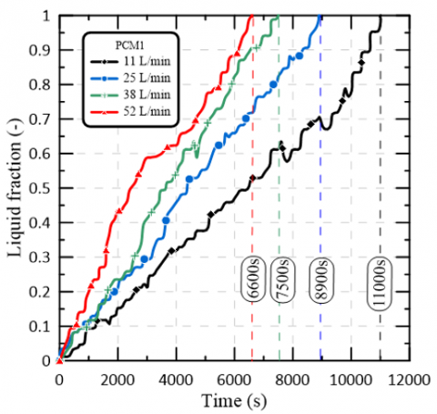
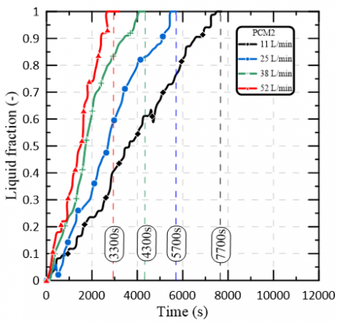
On the other hand, the melting fraction is shown in Figures 4(a) and 4(b). When the rate of flow into the system is steadily raised, both the rate at which the temperature rises and the rate at which melting occurs are considerably accelerated. When the flow rate is increased from 11 L/min to 52 L/min, the complete melting times are reduced by 12%, 15.7%, and 19.09% for pcm1, and by 23.25%, 24.5%, and 25% for pcm2. This is as a result of the fact that the quantity of heat that is transferred from the HTF to the PCM increases in proportion to the rise in the inlet flow rate. To phrase this another way, the PCM's temperature will rise at a greater rate per unit of time, which will result in an increase in the PCM's total heat storage capacity. When the intake flow rate is more than 11 liters per minute, the flow condition of HTF inside the copper tube changes from laminar flow to fully developed turbulent flow. Nevertheless, the convective heat transfer coefficient will gradually decrease in conjunction with an increase in the flow rate.
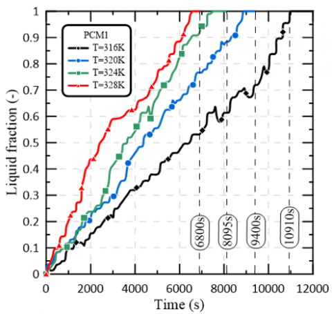
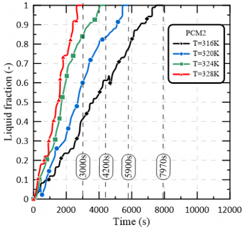
The time-dependent melting fraction is depicted in Figure 5(a,b) at an intake flowrate of 11 L/min and inlet temperatures of 316 K, 320 K, 324 K, and 328 K, respectively. Obviously, the temperature of the input has a positive correlation with the amount of time that must pass before the heat transfer flow (HTF) can be considered to have completely stopped. There is a correlation between a lower PCM melting point and a faster PCM melting rate. The wide disparity in temperature that exists between PCMs and HTF is a significant contributor to the problem. Increases the temperature difference between the heat transfer fluid and the PCMs, hence facilitating a more effective interaction between the two. As Because of this, PCM1 will begin melting before PCM2, which will result in a reduction in the amount of time required to store the heat.
Figure 3. PCM temperature vs Melting time
(a)
(b)
Figure 4. (a) PCM1 liquid faction vs Melting time at different inlet volume flow rate; (b) PCM2 liquid faction vs Melting time at different volume flow rate
(a)
(b)
Figure 5. (a) PCM1 liquid faction vs Melting time at different inlet temperature; (b) PCM2 liquid faction vs Melting time at different inlet temperature
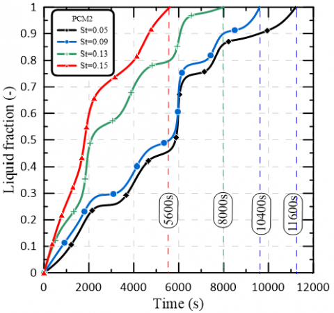
The melting fraction versus time for PCM1 and PCM2 is depicted in Figure 6 (a,b), where the Stefan numbers are 0.05, 0.09, 0.13, and 0.15 respectively. Figure 6 (a,b) indicates that the higher Stefan number of the PCM1 causes an acceleration in the rate at which the melting fraction increases. The Stefan number illustrates the disparity that exists between the melting temperature of the PCM and its surface temperature in terms of the latent heat of fusion. The rate at which the ice melts is impacted by this fluctuation. A reduction in the Stefan number causes a hastening of the melting rate.
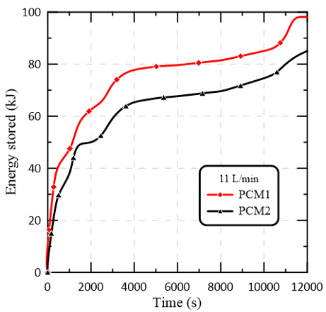
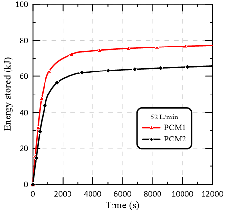
When comparing the amounts of energy stored at PCM1 and PCM2, Figure 7 (a,b) demonstrates that the amount of energy stored at PCM1 is greater than that stored at PCM2. When the flow rate is lowest, the amount of energy that can be stored grows by 12.85%, and when the flow rate is largest, it grows by 15%.
(a)
(b)
Figure 6. (a) PCM1 liquid faction vs Melting time at different Stefan number; (b) PCM2 liquid faction vs Melting time at different Stefan number
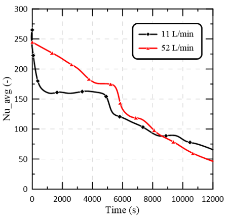
The average Nusselt numbers for PCM1 and PCM2 over time are plotted in Figure 8 for a variety of intake volume flows and inlet temperatures. Global melting can be broken down into three phases, based on how quickly the Nusselt number is changing: thermal conduction, convection, convection wearying, and thermal conduction recapture. When heat is being stored, thermal conduction predominates, leading to a high Nusselt number. Initial melting is characterized by low heat resistance because just a thin coating of liquid covers the melt. The rate at which they melt is enhanced. Due to a rise in the impedance to heat transmission at the solid-liquid interface, PCM's melting point lowers. A decrease in the Nusselt number. Nusselt number reaches a plateau, and convective heat transmission becomes dominant, marking the beginning of the second stage of melting. The Nusselt number, a measure of the rate of heat transfer, remains constant throughout convection. Over time, the addition of liquid PCM to the top layer enhanced heat resistance and diminished convection intensity. When the top layer of solid PCM melts, local convection ceases and liquid conduction restarts at a slower rate. The value of Nusselt's index is decreasing. Figure 8 demonstrates that an increase in the HTF flow velocity and the Nusselt number during convection leads to a more dramatic increase in convection intensity.
(a)
(b)
Figure 7. (a) Energy stored vs Melting time at minimum volume flow rate; (b) Energy stored vs Melting time at maximum volume flow rate
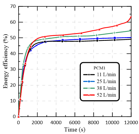
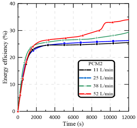
In Figure 9(a), it can be noted the energy efficiency of PCM1 increase with increasing volume flow rate by 2.12%, 6,95 and 12.6%. While Figure 9(b), the energy efficiency of PCM2 increasing by 1.92%, 7.1 and 12.1%. Also, it can be noted the energy efficiency of PCM1 increase by 47% then PCM2 at 52 L/min, while increase by 43% at 11 L/min.
Figure 8. Average Nusselt number vs Melting time at minimum and maximum volume flow rate
(a)
(b)
Figure 9. (a) PCM1 Energy efficiency vs Melting time at different volume flow rate; (b) PCM2 Energy efficiency vs Melting time at different volume flow rate
4.2 Exergy analysis
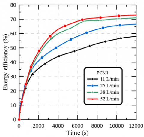
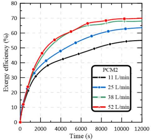
Exergy efficiency over time is studied for each scenario at different volume flow rate to evaluate system performance. As seen in Figure 10(a), the exergy efficiency of PCM1 increase with increasing volume flow rate by 6.66%, 8.33% and 16.17%. While Figure 10(b), the exergy efficiency of PCM2 increasing by 3%, 7.21 and 11.29%. Also, it can be noted the exergy efficiency of PCM1 increase by 9.45% then PCM2 at 52 L/min, while increase by 8.47% at 11 L/min.
(a)
(b)
Figure 10. (a) PCM1 Exergy efficiency vs Melting time at different volume flow rate; (b) PCM2 Exergy efficiency vs Melting time at different volume flow rate
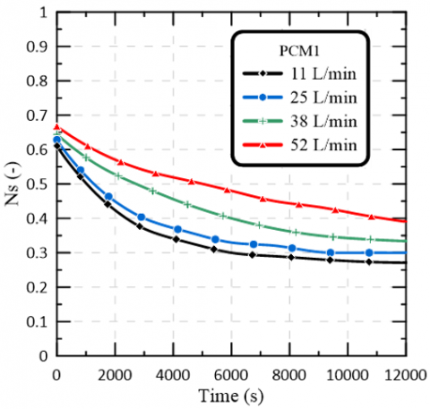
Finally, for a given volume flow rate, melting time decreases this entropy generation number as shown in Figure 11. A lower entropy generation number is the result of this behaviours since less energy is lost during the heat exchange. Furthermore, as the entropy generation number decreases, energy efficiency and system performance improve. As a result, these increase the amount of energy that may be stored in PCM during its melting phase. It's important to note that workout efficiency is a deciding element, even though it improves with time. The designer's goal may be to minimize melting time or maximize energy efficiency. If we only have so much time to store heat, optimizing for maximum energy efficiency and smallest entropy production number might not be the greatest choice. For instance, longer times may be required to maximize exergy efficiency and minimize entropy formation.
(a)
(b)
Figure 11. (a) PCM1 Entropy generation number vs Melting time at different volume flow rate; (b) PCM2 Entropy generation number vs Melting time at different volume flow rate
Present work leads to valuable conclusions such as:
The entropy generation number (associated with the losses in a process) falls as the average temperature of PCM rises.
|
T |
Temperature (control volume) (K) |
|
Tm |
Melting temperature (K) |
|
t |
Melting time (s) |
|
$\mathrm{T}_0$ |
Dead state temperature (K) |
|
$\mathrm{P}_0$ |
Dead state pressure (K) |
|
u |
Velocity of water $\left(\frac{\mathrm{m}}{\mathrm{s}}\right)$ |
|
z |
Elevation (m) |
|
g |
Specific gravity |
|
h |
Enthalpy of water $\left(\frac{\mathrm{kJ}}{\mathrm{kg}}\right)$ |
|
s |
Entropy of water $\left(\frac{\mathrm{kJ}}{\mathrm{kg} \cdot \mathrm{K}}\right)$ |
|
$\dot{W}_{C V}$ |
Control volume work (W) |
|
Q |
Heat storage capacity (kJ) |
|
q |
Average heat flux $\left(\frac{w}{m^2}\right)$ |
|
L |
Latent heat of PCM $\left(\frac{\mathrm{kJ}}{\mathrm{kg}}\right)$ |
|
$\dot{m}$ |
Mass flow rate $\left(\frac{\mathrm{kg}}{\mathrm{S}}\right)$ |
|
$\psi$ |
Exergy flow $\left(\frac{\mathrm{kJ}}{\mathrm{kg}}\right)$ |
|
$C_p$ |
Specific heat at constant pressure $\left(\frac{\mathrm{kJ}}{\mathrm{kg} \cdot \mathrm{K}}\right)$ |
|
$c p_s$ |
Solid specific heat of paraffin $\left(\frac{\mathrm{kJ}}{\mathrm{kg} \cdot \mathrm{K}}\right)$ |
|
$c p_l$ |
Liquid specific heat of paraffin $\left(\frac{\mathrm{kJ}}{\mathrm{kg} \cdot \mathrm{K}}\right)$ |
|
$c p_f$ |
Specific heat of HTF $\left(\frac{\mathrm{kJ}}{\mathrm{kg} \cdot \mathrm{K}}\right)$ |
|
W |
Total uncertainty in the measurement |
|
Re |
Reynold number |
|
st |
Stefan number |
|
$N_S$ |
Entropy generation number |
|
Nu |
Nusselt number |
|
Greek symbols |
|
|
λ |
Melting fraction |
|
ρ |
Density (kg/m3) |
|
µ |
Dynamic viscosity (kg/m·s) |
|
η |
Energy efficiency (%) |
|
$\eta_{e x}$ |
Exergy efficiency (%) |
|
Subscripts |
|
|
s |
Solid |
|
l |
Liquid |
|
m |
Melting |
|
ini |
Initial |
|
in |
Inlet |
|
out |
Outlet |
|
f |
Fluid |
|
0 |
Dead state |
|
dest |
Destruction |
|
TP |
triple pipe |
|
Abbreviation |
|
|
PCM |
Phase Change Material |
|
HTF |
Heat Transfer Fluid |
|
CV |
Control volume |
[1] Garg, H.P., Mullick, S.C., Bhargava, A.K. (1985). Solar thermal energy storage. Springer Dordrecht. https://doi.org/10.1007/978-94-009-5301-7
[2] Markandeyulu, T., Devanuri, J.K., Kumar, K. (2016). On the suitability of phase change material (PCM) for thermal management of electronic components. Indian Journal of Science and Technology, 9(S1): 1-4. https://doi.org/10.17485/ijst/2016/v9is1/107939
[3] Jaya Krishna, D. (2018). Operational time and melt fraction based optimization of a phase change material longitudinal fin heat sink. Journal of Thermal Science and Engineering Applications, 10(6): 064502. https://doi.org/10.1115/1.4040988
[4] Oró, E., De Gracia, A., Castell, A., Farid, M.M., Cabeza, L.F. (2012). Review on phase change materials (PCMs) for cold thermal energy storage applications. Applied Energy, 99: 513-533. https://doi.org/10.1016/j.apenergy.2012.03.058
[5] Silva, T., Vicente, R., Rodrigues, F. (2016). Literature review on the use of phase change materials in glazing and shading solutions. Renewable and Sustainable Energy Reviews, 53: 515-535. https://doi.org/10.1016/j.rser.2015.07.201
[6] Salunkhe, P.B. (2017). Investigations on latent heat storage materials for solar water and space heating applications. Journal of Energy Storage, 12: 243-260. https://doi.org/10.1016/j.est.2017.05.008
[7] Agyenim, F., Eames, P., Smyth, M. (2010). Heat transfer enhancement in medium temperature thermal energy storage system using a multitube heat transfer array. Renewable Energy, 35(1): 198-207. https://doi.org/10.1016/j.renene.2009.03.010
[8] Liu, H., Li, S., Chen, Y., Sun, Z. (2014). The melting of phase change material in a cylinder shell with hierarchical heat sink array. Applied Thermal Engineering, 73(1): 975-983. https://doi.org/10.1016/j.applthermaleng.2014.08.062
[9] Jesumathy, S.P., Udayakumar, M., Suresh, S., Jegadheeswaran, S. (2014). An experimental study on heat transfer characteristics of paraffin wax in horizontal double pipe heat latent heat storage unit. Journal of the Taiwan Institute of Chemical Engineers, 45(4): 1298-1306. https://doi.org/10.1016/j.jtice.2014.03.007
[10] Esapour, M., Hosseini, M.J., Ranjbar, A.A., Pahamli, Y., Bahrampoury, R. (2016). Phase change in multi-tube heat exchangers. Renewable Energy, 85: 1017-1025. https://doi.org/10.1016/j.renene.2015.07.063
[11] Liu, J., Xu, C., Ju, X., Yang, B., Ren, Y., Du, X. (2017). Numerical investigation on the heat transfer enhancement of a latent heat thermal energy storage system with bundled tube structures. Applied Thermal Engineering, 112: 820-831. https://doi.org/10.1016/j.applthermaleng.2016.10.144
[12] Kousha, N., Rahimi, M., Pakrouh, R., Bahrampoury, R. (2019). Experimental investigation of phase change in a multitube heat exchanger. Journal of Energy Storage, 23: 292-304. https://doi.org/10.1016/j.est.2019.03.024
[13] Joybari, M.M., Seddegh, S., Wang, X., Haghighat, F. (2019). Experimental investigation of multiple tube heat transfer enhancement in a vertical cylindrical latent heat thermal energy storage system. Renewable Energy, 140: 234-244. https://doi.org/10.1016/j.renene.2019.03.037
[14] Hosseini, M.J., Ranjbar, A.A., Rahimi, M., Bahrampoury, R. (2015). Experimental and numerical evaluation of longitudinally finned latent heat thermal storage systems. Energy and Buildings, 99: 263-272. https://doi.org/10.1016/j.enbuild.2015.04.045
[15] Rathod, M.K., Banerjee, J. (2015). Thermal performance enhancement of shell and tube Latent Heat Storage Unit using longitudinal fins. Applied Thermal Engineering, 75: 1084-1092. https://doi.org/10.1016/j.applthermaleng.2014.10.074
[16] Wang, P., Yao, H., Lan, Z., Peng, Z., Huang, Y., Ding, Y. (2016). Numerical investigation of PCM melting process in sleeve tube with internal fins. Energy Conversion and Management, 110: 428-435. https://doi.org/10.1016/j.enconman.2015.12.042
[17] Yang, X., Lu, Z., Bai, Q., Zhang, Q., Jin, L., Yan, J. (2017). Thermal performance of a shell-and-tube latent heat thermal energy storage unit: Role of annular fins. Applied Energy, 202: 558-570. https://doi.org/10.1016/j.apenergy.2017.05.007
[18] Abdulateef, A.M., Mat, S., Sopian, S., Abdulateef, J., Gitan, A.A. (2017). Experimental study of melting phase-change material in a triplex tube heat exchanger fin. Solar Energy, 155: 142-153. https://doi.org/10.1016/j.solener.2017.06.024
[19] Long, J. (2008). Numerical and experimental investigation for heat transfer in triplex concentric tube with phase change material for thermal energy storage. Solar Energy, 82(11): 977-985. https://doi.org/10.1016/j.solener.2008.05.006
[20] Başal, B., Ünal, A. (2013). Numerical evaluation of a triple concentric-tube latent heat thermal energy storage. Solar Energy, 92: 196-205. https://doi.org/10.1016/j.solener.2013.02.032
[21] Elbahjaoui, R., El Qarnia, H., Naimi, A. (2018). Thermal performance analysis of combined solar collector with triple concentric-tube latent heat storage systems. Energy and Buildings, 168: 438-456. https://doi.org/10.1016/j.enbuild.2018.02.055
[22] Al-Abidi, A.A., Mat, S., Sopian, K., Sulaiman, M.Y., Mohammad, A.T. (2013). Experimental study of PCM melting in triplex tube thermal energy storage for liquid desiccant air conditioning system. Energy and Buildings, 60: 270-279. https://doi.org/10.1016/j.enbuild.2013.01.031
[23] Mat, S., Al-Abidi, A.A., Sopian, K., Sulaiman, M.Y., Mohammad, A.T. (2013). Enhance heat transfer for PCM melting in triplex tube with internal–external fins. Energy Conversion and Management, 74, 223-236. https://doi.org/10.1016/j.enconman.2013.05.003
[24] Elfeky, K.E., Ahmed, N., Wang, Q. (2018). Numerical comparison between single PCM and multi-stage PCM based high temperature thermal energy storage for CSP tower plants. Applied Thermal Engineering, 139: 609-622. https://doi.org/10.1016/j.applthermaleng.2018.04.122
[25] Meng, Z.N., Zhang, P. (2017). Experimental and numerical investigation of a tube-in-tank latent thermal energy storage unit using composite PCM. Applied Energy, 190: 524-539. https://doi.org/10.1016/j.apenergy.2016.12.163
[26] Wang, W.W., Wang, L.B., He, Y.L. (2015). The energy efficiency ratio of heat storage in one shell-and-one tube phase change thermal energy storage unit. Applied Energy, 138: 169-182. https://doi.org/10.1016/j.apenergy.2014.10.064
[27] Wang, W.W., Wang, L.B., He, Y.L. (2016). Parameter effect of a phase change thermal energy storage unit with one shell and one finned tube on its energy efficiency ratio and heat storage rate. Applied Thermal Engineering, 93: 50-60. https://doi.org/10.1016/j.applthermaleng.2015.08.108
[28] Xu, Y., Ren, Q., Zheng, Z.J., He, Y.L. (2017). Evaluation and optimization of melting performance for a latent heat thermal energy storage unit partially filled with porous media. Applied Energy, 193: 84-95. https://doi.org/10.1016/j.apenergy.2017.02.019
[29] Kaizawa, A., Kamano, H., Kawai, A., Jozuka, T., Senda, T., Maruoka, N., Akiyama, T. (2008). Thermal and flow behaviors in heat transportation container using phase change material. Energy Conversion and Management, 49(4): 698-706. https://doi.org/10.1016/j.enconman.2007.07.022
[30] Li, Y.Q., He, Y.L., Wang, Z.F., Xu, C., Wang, W. (2012). Exergy analysis of two phase change materials storage system for solar thermal power with finite-time thermodynamics. Renewable Energy, 39(1): 447-454. https://doi.org/10.1016/j.renene.2011.08.026
[31] Jegadheeswaran, S., Pohekar, S.D., Kousksou, T. (2010). Exergy based performance evaluation of latent heat thermal storage system: A review. Renewable and Sustainable Energy Reviews, 14(9): 2580-2595. https://doi.org/10.1016/j.rser.2010.07.051
[32] Rahimi, M., Ardahaie, S.S., Hosseini, M.J., Gorzin, M. (2020). Energy and exergy analysis of an experimentally examined latent heat thermal energy storage system. Renewable Energy, 147: 1845-1860. https://doi.org/10.1016/j.renene.2019.09.121
[33] Li, G. (2015). Energy and exergy performance assessments for latent heat thermal energy storage systems. Renewable and Sustainable Energy Reviews, 51: 926-954. https://doi.org/10.1016/j.rser.2015.06.052
[34] Kousksou, T., Strub, F., Lasvignottes, J.C., Jamil, A., Bédécarrats, J.P. (2007). Second law analysis of latent thermal storage for solar system. Solar Energy Materials and Solar Cells, 91(14): 1275-1281. https://doi.org/10.1016/j.solmat.2007.04.029
[35] Erek, A., Dincer, I. (2009). A new approach to energy and exergy analyses of latent heat storage unit. Heat Transfer Engineering, 30(6): 506-515. https://doi.org/10.1080/01457630802529271
[36] Rahimi, M., Ardahaie, S.S., Hosseini, M.J., Gorzin, M. (2020). Energy and exergy analysis of an experimentally examined latent heat thermal energy storage system. Renewable Energy, 147: 1845-1860. https://doi.org/10.1016/j.renene.2019.09.121
[37] Al-Abbas, A.H., Mohammed, A.A., Hassoon, A.S. (2021). Exergy analysis of Shell and helical coil heat exchanger and design optimization. Heat and Mass Transfer, 57(5): 797-806. https://doi.org/10.1007/s00231-020-02993-9
[38] Zhang, N., Yuan, Y., Cao, X., Du, Y., Zhang, Z., Gui, Y. (2018). Latent heat thermal energy storage systems with solid–liquid phase change materials: A review. Advanced Engineering Materials, 20(6): 1700753. https://doi.org/10.1002/adem.201700753
[39] Rezaei, M., Anisur, M.R., Mahfuz, M.H., Kibria, M.A., Saidur, R., Metselaar, I.H.S.C. (2013). Performance and cost analysis of phase change materials with different melting temperatures in heating systems. Energy, 53: 173-178. https://doi.org/10.1016/j.energy.2013.02.031
[40] Moffat, R.J. (1988). Describing the uncertainties in experimental results. Experimental Thermal and Fluid Science, 1(1): 3-17. https://doi.org/10.1016/0894-1777(88)90043-X