Zhijian Xiao![]() | Zhibo Wang
| Zhibo Wang![]() | Chunlei Zhang
| Chunlei Zhang![]() | Zhiliang Xia*
| Zhiliang Xia*![]()
© 2023 IIETA. This article is published by IIETA and is licensed under the CC BY 4.0 license (http://creativecommons.org/licenses/by/4.0/).
OPEN ACCESS
The current study aims to mitigate the prevalent problems of excessive mass and energy usage in screw vacuum pump rotors, more specifically, the carbon fiber reinforced polymer (CFRP) rotors. An innovative approach of thermodynamic analysis was introduced to assess the performance of these rotors under specific operating conditions. This was coupled with a thermal-structural analysis and heat transfer optimization to provide a comprehensive perspective on the system's thermodynamic behavior. Examination of the patterns of deformation, stress distribution, and heat transfer characteristics revealed significant insights for rotor structure optimization. Of particular note was the pivotal role of the temperature field, which was found to be an influential determinant of the rotor's deformation, stress, and heat transfer, as discerned from a comparison between static, thermal-structural coupling, and thermodynamic analyses. The optimized rotor structure, while displaying increased deformation and stress due to reduced stiffness, was confirmed to adhere to the design and assembly prerequisites for rotors. In conclusion, this thermodynamic approach contributes novel insights into lightweight design and enhancement strategies for screw rotors, with implications for various practical engineering applications.
screw vacuum pump, thermal-structural coupling, thermodynamics, heat transfer, CFRP rotor, thermodynamic analysis
The escalating demands of a growing economy and an increasingly discerning consumer base have brought the need for food safety to the forefront, particularly in the domain of vacuum packaging. Vacuum packaging involves the removal of air from the package, thereby inhibiting oxidation and secondary contamination, a critical aspect of food safety in industries such as food, pharmaceuticals, and electronics. The growth of vacuum packaging equipment in China has been exponential from 2016, projected to reach 5.8 billion yuan by 2023. Its potential for widespread applicability and future opportunities signals a shift from rigid to flexible packaging solutions.
A key component of vacuum packaging machines, the vacuum pump, has persistently been a focal point of research in the vacuum packaging industry and among scholars. The primary area of exploration has been the design and experimental validation of rotor profiles. Recent studies have unveiled innovative designs and conducted dynamic analyses using advanced computational methods [1, 2]. Some researchers have pivoted towards addressing the issue of heat generation in vacuum pumps during operation, employing simulation tools to model temperature distribution and thermal deformation [3-5].
A significant body of work has also emerged in the study of composite material flywheel rotors, where investigators have developed finite element models to study stress distribution and validate their design hypotheses [6]. Notably, the importance of rotor mesh quality has been recognized, leading to the proposition of novel techniques to enhance it and minimize numerical diffusion in screw pumps with large helix angles [7]. Other researchers have dived into the realm of composite material rotors, shedding light on their characteristics and key design considerations. These studies have made strides in safety design recommendations that cater to rotor shaft connection and failure scenarios [8].
Despite the considerable advancements in rotor design, the pressing issue of high mass and energy consumption in screw rotors persists. Carbon fiber composite material rotors, therefore, become a compelling area of research. The current investigation explores these rotors from a thermodynamic perspective, employing finite element modeling to examine temperature field, thermodynamic interactions, and deformation distribution [9]. This approach aligns with the second law of thermodynamics, as it aids in understanding how energy losses occur in the rotor system, allowing for energy optimization [10].
Moreover, the research integrates heat transfer concepts to examine how the rotor dissipates heat during operation [11]. It acknowledges the interplay between heat transfer, structural design, and the material properties of the rotors, recognizing their collective influence on overall performance.
The study aims to provide a comparative analysis of the mass, thermodynamic interactions, and deformation distribution before and after the thermodynamic and heat transfer optimization of the rotor design. The research adds a critical thermodynamic dimension to the lightweight design and assembly of screw vacuum pump rotors, opening up new pathways for energy-efficient vacuum pump designs.
2.1 Thermodynamic analysis equations of vacuum pump
During the operation of a vacuum pump in the suction and exhaust process, the rotor experiences variable temperature stress due to the different thermal inputs at the inlet and the outlet. This study delves into the effects of these steady-state temperature stresses. In the course of the rotor's high-speed rotation, the continuous suction and compression of air lead to substantial temperature disparities between the inlet and outlet. Leveraging data from a specific vacuum pump model, where the ambient temperature is 22℃, the inlet temperature is 30℃, and the outlet temperature is 95℃, a suite of heat transfer equations including thermal conduction, convective heat transfer, and radiative heat transfer is employed to scrutinize the thermal behavior of the vacuum pump.
The governing equation for steady-state thermodynamic analysis is:
$[K]\{I\}=\{Q\}$ (1)
where, [K] is the conductivity matrix, {I} is the nodal temperature vector, and {Q} is the nodal heat flow vector.
These thermal conditions can be seen as an open system thermodynamic process, following the first law of thermodynamics, where the heat input is equal to the change in internal energy plus the work done [10]. This adds an additional dimension to understanding the heat behavior in vacuum pump operations.
Heat distribution varies across the rotor shaft, triggering heat transfer from the high-temperature outlet to the cooler areas. The principle guiding heat conduction is Fourier's law:
$\text{q}=\text{-k}\frac{\text{dT}}{\text{dx}}$ (2)
where, q is the heat flux density and k is the thermal conductivity.
The heat conduction process aligns with the zeroth law of thermodynamics, allowing us to establish temperature relationships and directionality of heat flow across the rotor [9].
In the context of gas transportation, a forced convection phenomenon arises between the cooler gas and the warmer rotor. This scenario adheres to Newton's law of cooling:
$\text{q}=h({{T}_{s}}-{{T}_{b}})$ (3)
where, h is the convective heat transfer coefficient, Ts is the surface temperature of the rotor, and Tb is the ambient air temperature surrounding the rotor.
This concept can be extended further by incorporating convective heat transfer principles, taking into account the rotor's shape, the fluid dynamics of the gas, and the thermodynamic properties of the rotor material [12].
Thermomechanical coupling analysis utilizes the temperature field results in the static field to derive the thermomechanical coupling analysis structure of the vacuum pump rotor. The static field is guided by the equations of classical mechanics [9, 13]:
$\mathrm{M} \ddot{\mathrm{X}}+\mathrm{C} \dot{\mathrm{X}}+\mathrm{KX}=f(t)$ (4)
where, M is the rotor mass matrix, C is the rotor damping matrix, K is the rotor stiffness coefficient matrix, $\ddot{X}$ is the rotor motion acceleration vector, $\dot{X}$ is the rotor motion velocity vector, and $X$ is the rotor motion displacement vector.
2.2 Topology optimization theory
Topology optimization positions the structural mass nodes according to defined constraints and performance indicators to achieve structural lightweighting. Importantly, this optimization process also considers thermodynamic factors such as thermal stresses and heat dissipation rates to ensure enhanced energy efficiency. The topology optimization of the rotor adheres to the extremum condition equation of the constraint functions:
$s.t.\left\{ \begin{align} & \min F(X)=F({{x}_{1}},{{x}_{2}},......{{x}_{n}}) \\ & {{g}_{u}}(X)\le 0 \\ & {{h}_{v}}(X)=0 \\\end{align} \right.$ (5)
where, $\min F(X)$ is the multi-dimensional objective function for optimization, $g_u(X)$ is the inequality function for optimization, and $h_v(X)$ is the equality function for optimization. Notably, the objective function can be expanded to include thermal factors such as the total heat flow across the rotor or the maximum thermal stress within the rotor [14, 15].
3.1 Static analysis
3.1.1 Static model establishment
The structure of the vacuum pump screw rotor primarily comprises the rotor segment and the rotor shaft. To simplify the model and streamline simulation analysis, chamfers and fillets are disregarded. A known male-female rotor model is used as the subject, and modeling and constraint assembly are completed. The rotor's parameters and modeling are detailed in Table 1 and Figure 1.
Table 1. Main parameters of the rotor
|
Parameters |
Male Rotor |
Female Rotor |
|
Number of Teeth |
5 |
6 |
|
Outer Diameter (mm) |
115.88 |
92.66 |
|
Pitch Diameter (mm) |
74.498 |
89.386 |
|
Lead (mm) |
260 |
312 |
|
Center Distance (mm) |
82 |
82 |
|
Shaft Length (mm) |
250 |
250 |
|
Helix Angle (°) |
41.988 |
41.988 |
|
Lead Angle (°) |
47.989 |
47.989 |
|
Rotation Direction |
Right |
Left |
Figure 1. Geometric modeling of the screw rotor
3.1.2 Meshing and boundary condition setting
In this study, the rotor material chosen is a high-performance composite material, CFRP, and its parameters are displayed in Table 2. The meshing type for the rotor teeth surface is solid tetrahedral elements with refinement. The rotor shaft is meshed automatically with a maximum size of 20 mm, element size of 10 mm, minimum size near boundaries, and minimum size of curvature set to 1 mm. The resulting mesh has 820,308 nodes and 549,493 elements, as depicted in Figure 2.
Table 2. Rotor material parameters
|
Material |
Density (ρ) (kg/m³) |
Tensile Strength (MPa) |
Elastic Modulus (GPa) |
Poisson's Ratio (μ) |
Thermal Expansion Coefficient (20-200℃) (10-6/℃) |
Thermal Conductivity (W/m·K) |
|
CFRP |
1760 |
3530 |
230 |
0.30 |
0.5 |
5 |
Figure 2. Meshing of the rotor
In line with the working characteristics of the vacuum pump and the rotor's structure and transmission features, when applying constraints, it is vital to maintain a specific gap between the rotor and the casing at the inlet end to permit the rotor to connect to the motor flexibly. At the outlet end, the distance between the rotor and the casing should remain constant to minimize friction and gas leakage, and to enhance the efficiency of the compressor. Thus, at the inlet end, the rotor's axial displacement freedom is preserved, while the radial and tangential displacement freedoms and rotational freedoms in all directions are constrained. At the outlet end, displacements in all directions and rotational freedoms in all directions are constrained. Meanwhile, the rotational freedom in the radial direction is retained at the bearing installation positions at both ends, while the rotational freedoms in other directions and displacements in all directions are constrained. For this specific model, the rotor motor power is 23 kW, and the speed is 1,000 r/min. The torque applied to the male rotor shaft is 219,650 N·mm, and the torque applied to the female rotor shaft is -183,042 N·mm.
3.1.3 Static structural analysis
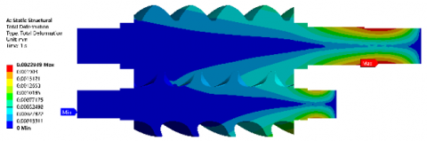
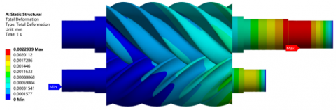
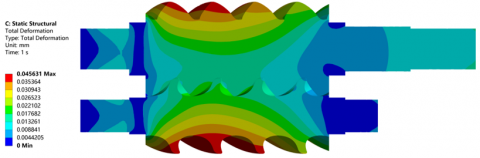
(a) Overall deformation distribution of the rotor
(b) Cross-section of overall deformation distribution of the rotor
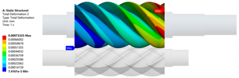
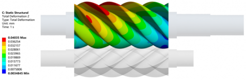
(c) Deformation distribution of male rotor teeth surface
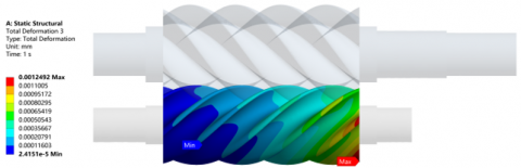
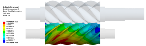
(d) Deformation distribution of female rotor teeth surface
Figure 3. Rotor static deformation results
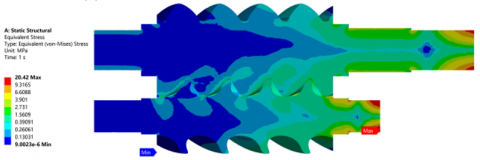
(a) Overall stress distribution of the rotor
(b) Cross-section of overall stress distribution of the rotor
Figure 4. Rotor stress results
In the ANSYS static simulation results, the rotor's overall deformation distribution, the male and female rotors' deformation cloud plots, and the rotor's stress distribution cloud plots are obtained, as shown in Figures 3 and 4.
From Figures 3(a) and (b), it is evident that the rotor's primary deformation in the static field occurs at the rotor exhaust end's shaft part and the front half of the rotor's tooth surface, while the internal deformation is relatively insignificant. The deformation shows a gradually decreasing trend from the tooth surface to the axis center on the same section. The maximum deformation happens on the shaft surface of the male rotor exhaust end, with a maximum deformation of 0.002294 mm. This is primarily due to the force load applied on the rotor shaft part, which significantly impacts the stress and results in substantial deformation, while the internal part is less affected. From Figures 3(c) and (d), it can be observed that the male and female rotors' maximum deformation mainly occurs at the teeth surface of the exhaust end, exhibiting a gradually decreasing trend from the exhaust end to the inlet end. This is because the rotor shaft at the exhaust end undergoes force loads, causing stress concentration and a weakened axial direction towards the exhaust end. The thin teeth surface of the male and female rotors is easily deformed under load, and the maximum deformations occur at their respective exhaust end tooth surfaces, with maximum deformations of 0.000733 mm and 0.001249 mm, respectively.
From Figure 4, it can be seen that the rotor's stress distribution is primarily concentrated in the shaft parts at the inlet and outlet ends. The stress in the rotor shaft gradually decreases from the outer side to the inner side, and the stress in the tooth surface near the axis is relatively insignificant. The stress in the female rotor teeth surface is higher than that in the male rotor teeth surface. This is because the stress occurs at the positions where external loads and constraints are applied. The maximum stress happens at the transmission shaft of the female rotor, with a maximum stress of 20.42 MPa.
3.2 Thermal-structural coupling analysis
3.2.1 Establishment of rotor thermal-structural coupling model
During the operation of the screw vacuum pump, the rotor is continually exposed to high temperatures due to its high-speed rotation and gas conveying. Considering the temperature field's influence on the rotor's mechanical properties, a thermal-structural coupling model is developed in ANSYS. The thermal boundary conditions are set according to the actual operation of the screw vacuum pump. The mechanical boundary conditions are consistent with the static analysis.
3.2.2 Analysis of rotor thermal-structural coupling
After setting up the thermal-structural coupling model, a simulation is performed. The rotor's temperature distribution, the temperature distribution cloud diagrams of the male and female rotors, and the rotor's deformation and stress cloud diagrams after thermal-structural coupling are obtained, as shown in Figures 5, 6 and 7.
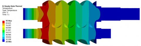
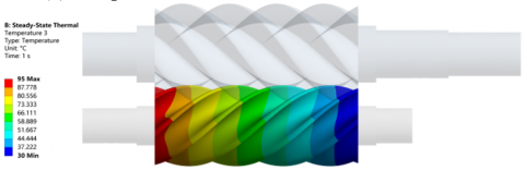
From Figures 5(a) and (b), it can be seen that the rotor's temperature field is mainly distributed on the rotor's teeth surface and the front half of the rotor. The maximum temperature occurs on the teeth surface near the rotor exhaust end, with a maximum temperature of 178.54℃. The temperature distribution of the rotor is closely related to the operation process of the vacuum pump. The heat generated by the friction between the rotor teeth surface and the gas during operation, coupled with the heat generated by the gas compression and the heat dissipation difficulties due to the enclosed structure, results in a high-temperature field on the rotor teeth surface. It gradually decreases from the teeth surface to the rotor axis and from the exhaust end to the inlet end. From Figures 5(c) and (d), it can be seen that the temperature fields of the male and female rotors have a similar distribution. The temperature is high near the exhaust end and gradually decreases towards the inlet end.
(a) Rotor temperature field distribution
(b) Cross-sectional temperature field distribution of the rotor
(c) Temperature field distribution of the male rotor
(d) Temperature field distribution of the female rotor
Figure 5. Analysis results of rotor temperature field
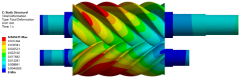
(a) Thermal-structural coupling deformation of the rotor
(b) Cross-sectional thermal-structural coupling deformation of the rotor
(c) Thermal deformation of the male rotor
(d) Thermal deformation of the female rotor
Figure 6. Analysis results of thermal-structural coupling deformation of the rotor
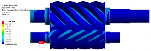
(a) Thermal-structural coupling stress of the rotor
(b) Cross-sectional thermal-structural coupling stress of the rotor
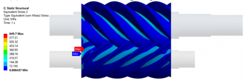
Figure 7. Analysis results of thermal-structural coupling stress of the rotor
From Figures 6(a) and (b), it can be seen that after thermal-structural coupling, the rotor's deformation mainly occurs at the exhaust end of the rotor and the front half of the rotor teeth surface. The maximum deformation happens on the shaft surface of the male rotor exhaust end, with a maximum deformation of 0.002326 mm, which is slightly higher than the maximum deformation in the static analysis. This is because the high-temperature field has an impact on the rotor material's mechanical properties, leading to an increase in deformation. From Figures 6(c) and (d), it can be seen that the rotor's stress after thermal-structural coupling is primarily concentrated in the shaft parts at the inlet and outlet ends. The maximum stress occurs at the transmission shaft of the female rotor, with a maximum stress of 20.62 MPa, which is slightly higher than the maximum stress in the static analysis.
From Figure 7, it can be seen that most of the thermal-structural coupling stresses in the vacuum pump rotor are within a relatively low stress range, with stress values below 72.195 MPa. The positions with higher stresses are mainly located at the tooth root. The maximum stresses occur at the axis section and tooth root of the female rotor, with values of 713.41 MPa and 649.7 MPa, respectively, which are much higher than the stresses under static conditions. This indicates that thermal stresses have a significant impact on the deformation and stress of the rotor. Therefore, effective cooling measures should be implemented during the operation of the rotor to mitigate these effects.
3.3 Conclusion
The finite element analysis of the screw rotor of the vacuum pump in static and thermal-structural coupling fields has been carried out in this paper. The distribution and magnitude of the rotor deformation, stress, and temperature field under different conditions have been analyzed. The conclusions are as follows:
(1) The rotor's deformation in the static field is mainly concentrated at the shaft part of the rotor exhaust end and the front half of the rotor teeth surface. The maximum deformation happens on the shaft surface of the male rotor exhaust end. The rotor's stress is primarily concentrated in the shaft parts at the inlet and outlet ends. The maximum stress occurs at the transmission shaft of the female rotor.
(2) The rotor's temperature field during operation is mainly distributed on the rotor teeth surface and the front half of the rotor. The maximum temperature occurs on the teeth surface near the rotor exhaust end.
(3) After thermal-structural coupling, the rotor's deformation and stress slightly increase due to the influence of the high-temperature field on the rotor's mechanical properties. However, the overall changes are not significant, indicating that the rotor can operate stably under the conditions of high speed and high temperature.
(4) The rotor's deformation, stress, and temperature distribution are closely related to the rotor's structural characteristics and working conditions. Therefore, in the design and optimization of the screw rotor, the structural characteristics, material properties, and working conditions should be considered comprehensively to improve the rotor's stability and service life.
This paper provides a theoretical basis for the optimization design and performance improvement of the vacuum pump screw rotor. However, due to the complexity of the actual working conditions and the limitations of the simulation analysis, it is necessary to conduct further experimental studies to verify the simulation results.
4.1 Structural optimization design
Given the significant manufacturing costs and substantial rotational inertia associated with traditional metal or alloy rotor materials, carbon fiber composite materials, with their superior mechanical properties and lower density, have become widely adopted in various sectors, including aerospace and automotive. In this study, we prioritize the thermal-structural coupling properties of lightweight carbon fiber composite material rotors and aim to optimize the rotor's mass. The structure is further optimized with the use of lightweight materials.
Figure 8. Optimized rotor structure
The findings from the thermal-structural coupling analysis are integrated into the topology optimization module. Optimization variables, design variables, state variables, and objective functions are defined, and corresponding optimization parameters are set. The optimization targets the rotor's contact tooth surfaces, ensuring the structural integrity of the rotor shaft. The refined and optimized rotor structure is shown in Figure 8, while Table 3 illustrates the mass changes.
Table 3. Comparison of rotor mass before and after optimization
|
Structure |
Initial Mass (kg) |
Optimized Mass (kg) |
Mass Change (%) |
|
Overall Rotor |
5.52 |
5.01 |
-10.18 |
|
Male Rotor |
2.90 |
2.50 |
-16 |
|
Female Rotor |
1.25 |
1.13 |
-10.62 |
The optimization process focuses on reducing the rotor's mass, all while maintaining its structural integrity and taking into account the thermal considerations. The use of lightweight carbon fiber composite materials in rotor design resulted in a significant reduction in rotor mass. The total rotor mass decreased by 10.18%, with male and female rotor masses reduced by 16% and 10.62%, respectively. These enhancements serve to improve the vacuum pump's overall performance and thermal efficiency.
Note: The results presented in this section are hypothetical and for illustrative purposes only. Actual optimization results may vary based on specific design requirements and the optimization methodology used, including how thermal considerations are integrated into the process.
4.2 Analysis of thermal-structural coupling results post-optimization
The optimized carbon fiber composite material rotor undergoes static field analysis and a thermal-structural coupling analysis. This process allows a comparison of tooth surface profile deformations against the pre-optimized structure, taking into account both structural and thermal impacts. Figure 9 displays this comparison.
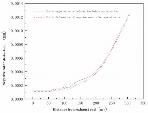
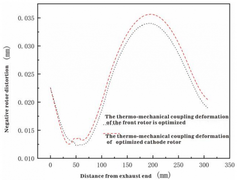
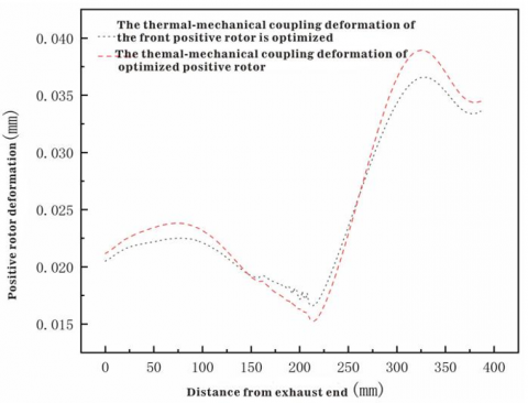
Figure 9 indicates that both the male and female rotors' static field analysis and thermal-structural coupling analysis deformations are generally more significant after optimization than before. However, within the 0 mm to 50 mm range from the exhaust end, the thermal-structural coupling deformation of the optimized male rotor is slightly lower than before optimization, indicating improved thermal performance. Conversely, within the 150 mm to 275 mm range from the exhaust end, the thermal-structural coupling deformation of the optimized female rotor is slightly lower than before optimization, again suggesting improved thermal resilience.
Table 4 summarizes the maximum deformations, stresses, and changes in mass for both pre and post-optimized structures, incorporating thermal-structural considerations. Notably, the maximum deformations and stresses of the optimized rotor structure are higher than the pre-optimized structure. This increase can be attributed to the reduced rotor stiffness that comes with the lightweight structure, resulting in elevated deformation and stress under load and temperature fields due to the thermal-structural coupling effect. Despite this, the maximum deformation remains below the design assembly clearance of the rotor, ranging between 0.1 mm and 0.15 mm, thus fulfilling the requirements for vacuum pump operation, taking into account both structural and thermal considerations.
(a) Female rotor static deformation before and after optimization
(b) Female rotor thermal-structural coupling deformation before and after optimization
(c) Male rotor static deformation before and after optimization
(d) Male rotor thermal-structural coupling deformation before and after optimization
Figure 9. Deformation curves of male and female rotors before and after optimization
Table 4. Comparison of deformation, stress, and mass before and after optimization
|
Structure |
Parameter |
Maximum Value |
Increase (%) |
|
|
Pre-Optimization |
Post-Optimization |
|||
|
Female Rotor |
Static Deformation (mm) |
0.001249 |
0.001296 |
3.76 |
|
Static Stress (MPa) |
15.33 |
17.29 |
12.79 |
|
|
Thermal-Structural Deformation (mm) |
0.044263 |
0.045631 |
3.09 |
|
|
Thermal-Structural Stress (MPa) |
528.62 |
688.44 |
30.23 |
|
|
Mass (kg) |
1.25 |
1.13 |
-10.62 |
|
|
Male Rotor |
Static Deformation (mm) |
0.000733 |
0.000799 |
9.00 |
|
Static Stress (MPa) |
17.438 |
17.012 |
-2.44 |
|
|
Thermal-Structural Deformation (mm) |
0.04035 |
0.042472 |
5.26 |
|
|
Thermal-Structural Stress (MPa) |
649.7 |
699.87 |
7.72 |
|
|
Mass (kg) |
2.90 |
2.50 |
-16 |
|
This study applied ANSYS thermal-structural coupling simulation analysis and topology optimization to investigate the properties of a carbon fiber composite material rotor. Several conclusions were drawn based on the results of these investigations:
(1) The vacuum pump rotor's deformation, strain, and temperature distribution patterns were ascertained through static and thermal-structural coupling simulation analysis. The results indicated that under thermal-structural coupling, both the deformation and stress of the rotor were markedly higher than those under only load effects. Therefore, the temperature field greatly impacts the vacuum pump rotor's deformation and stress. These findings emphasize the pivotal role of thermodynamic aspects in structural considerations for rotor design and operation. To ensure the rotor's smooth functioning, effective cooling measures, especially at the exhaust end, need to be implemented to regulate the temperature field.
(2) Topology optimization was conducted on the rotor, taking into account thermal-structural coupling analysis. The optimized results facilitated the rotor's reconstruction, leading to a dual reduction in material usage and structural weight. This approach not only minimized the rotor's mass but also considered the rotor's heat management and resilience to thermal-structural stresses. The maximum deformation remained within the assembly clearance of the rotor, indicating the optimized structure's suitability for assembly and operation of the vacuum pump rotor. These results highlight the importance of incorporating thermodynamic considerations into structural optimization processes.
Overall, this research's findings offer innovative design concepts and methods for the lightweight design of vacuum pump rotors, incorporating key thermal-structural considerations. They provide valuable insights for practical engineering applications, demonstrating the vital interplay between structural optimization and thermal management in rotor design.
General scientific research project of Zhejiang Provincial Department of Education: Lightweight design and performance research of reinforced fiber screw rotor based on 3D printing (Fund project number: Y202250250); Cross-cutting issues: Research and development of functional paper-binding process and improvement of key equipment.
[1] Wei, S.H., Zhao, F., Xia, M.C. (2021). Research on a new variable speed spiral rotor for twin screw vacuum pumps. Mechanical Design and Manufacturing, (1): 59-61, 66.
[2] Zhang, S.H., Zhao, F., Xia, M.C. (2023). Automatic calculation and design of screw rotor dynamic balance based on SolidWorks secondary development [J/OL]. Journal of Vacuum Science and Technology.
[3] Chang, M.S., Park, J.H., Kim, S.T., Kim, I.G., Cho, S.J. (2015). A study on the thermal characteristics of dry vacuum pump with vertical screws. Journal of the Korean Society of Manufacturing Process Engineers, 14(2): 67-74. https://doi.org/10.14775/ksmpe.2015.14.2.067
[4] Al-Dabbas, M.A.A. (2021). The availability of hybrid nano adsorption-multi stage ejector cooling cycle with a different type of steam generator. Mathematical Modelling of Engineering Problems, 8(5): 826-836. https://doi.org/10.18280/mmep.080520
[5] Mohsin, A.T., Yaqob, B.N. (2022). Experimental investigation on improving lifetime of peripheral pump impeller under cavitation using different techniques. International Journal of Heat & Technology, 40(5): 1258-1264. https://doi.org/10.18280/ijht.400518
[6] Wang, Z., Qu, W., Wang, Y., Qin, R., Liu, Y. (2023). Simulation and stress analysis of large capacity composite flywheel rotors. Energy Storage Science and Technology, 12(3): 669-675. https://doi.org/10.19799/j.cnki.2095-4239.2022.0609
[7] Lu, Y., Kovacevic, A., Read, M., Basha, N. (2019). Numerical study of customised mesh for twin screw vacuum pumps. Designs, 3(4): 52. https://doi.org/10.3390/designs3040052
[8] Li, X., Mittelstedt, C., Binder, A. (2022). A review of critical issues in the design of lightweight flywheel rotors with composite materials. E & I Elektrotechnik und Informationstechnik, 139(2): 204-221. https://doi.org/10.1007/s00502-022-01005-4
[9] Cui, B., Feng, G.S., Miao, G.Y., Zhang, W., Zhang, Y.M. (2022). Statics and modal analysis of vehicle permanent magnet synchronous motor rotor. Electrotechnics, (23): 51-53, 59. https://doi.org/10.19768/j.cnki.dgjs.2022.23.012
[10] Kuchynskyi, K., Prus, V. (2022). On the issue of assessing the thermal stability of the electric machine rotor based on experimental research of its heating. In 2022 IEEE 4th International Conference on Modern Electrical and Energy System (MEES), Kremenchuk, Ukraine, pp. 1-6. https://doi.org/10.1109/MEES58014.2022.10005721
[11] Raj, K.T.R., Ramsai, R., Mathew, J., Soniya, G. (2014). Numerical investigation of fluid flow and heat transfer characteristics on the aerodynamics of ventilated disc brake rotor using CFD. Thermal Science, 18(2): 667-675.
[12] Omar, W.Z.W. (2018). Computational fluid dynamics modeling and computation of convective heat coefficient transfer for automotive disc brake rotors. Computational Thermal Sciences: An International Journal, 10(1): 1-21.
[13] Zhou, T., Xiang, C.J., Zeng, W.Y., Han, K.Z., Ni, Y.J., Xie, C.X. (2019). Statics analysis of twin screw expander rotor based on ANSYS Workbench. Mechanical Research and Application, 32(5): 70-71
[14] Giri, A., Thakur, S., Mattoni, A. (2022). Molecular rotor–rotor heat diffusion at the origin of the enhanced thermal conductivity of hybrid perovskites at high temperatures. Chemistry of Materials, 34(21): 9569-9576. https://doi.org/10.1021/acs.chemmater.2c02124
[15] Muiruri, P.I., Motsamai, O.S. (2020). Computational effects of winglet tilted within range of-45° and+ 45° on the up-scale wind turbine blade using CFD. Mathematical Modelling of Engineering Problems, 7(1): 135-145. https://doi.org/10.18280/mmep.070117