Jarosław Boryca![]() | Tomasz Wyleciał*
| Tomasz Wyleciał*![]() | Dariusz Urbaniak
| Dariusz Urbaniak![]()
© 2023 IIETA. This article is published by IIETA and is licensed under the CC BY 4.0 license (http://creativecommons.org/licenses/by/4.0/).
OPEN ACCESS
This paper investigates strategies for reducing fuel consumption during the heating of steel charge before plastic processing. The study examines the impact of flue gas recuperation for combustion air preheating and the utilization of enthalpy from hot charge supplied by COS. We conducted calculations to analyze the effect of combustion air temperature and charge temperature at the furnace inlet on fuel consumption. Furthermore, an estimation of potential cost savings in heating is presented. The results of the calculations show that the use of recuperation and enthalpy of the hot charge allows for significant economic and ecological savings. These savings can range from more than 30% to more than 60% in economic terms.
energy efficiency, steel heating furnace, steel charge heating, combustion air preheating, closed-loop energy management
Steel products are essential for constructing infrastructure and play a strategic role in the national economy. The iron and steel industry are one of the most energy-intensive, accounting for around 5% of total global energy consumption. Scientific and industrial research worldwide aims to improve the energy efficiency of the steel industry, including reducing the energy consumption costs of reheating furnaces in rolling mills [1]. Furnaces, which heat the charge before forming, are the most energy-intensive equipment in rolling mill sections [2-4].
In recent months, natural gas prices have fluctuated on the Polish and European markets. Therefore, Russia's invasion of Ukraine could threaten uninterrupted gas supplies from abroad [5], although no such threat was anticipated [6]. The outbreak of the war in Ukraine caused a sharp increase in the price of energy carriers. In Polish steelworks, this met with an immediate reaction in the form of seeking savings in gas consumption. In addition, military operations in Ukraine resulted in a reduction in gas supplies. Security of gas supply to end-users can be ensured by introducing natural gas off-take restrictions. Reducing fuel consumption is almost the most crucial aspect of steel mill production in such a situation.
This is a priority action also due to the price competitiveness of products in the steel market.
Apart from the employed technology, the operation of heating furnaces plays a decisive role in the process of heating a steel charge. Proper operation of the furnace can ensure minimization of heat consumption, scale loss as well as ensure high quality of the final products and semi-finished products [7-9]. Increasing the efficiency of heating furnaces is possible by modeling the phenomena occurring in them [10-13], including the oxidation of the charge [14-18].
One possible measure to reduce fuel (gas) consumption is using exhaust gas waste heat for combustion air heating (recovery). This can be achieved through two methods: the use of waste heat from the exhaust gases to heat the combustion air (recuperation), and the use of enthalpy of the hot charge. The analysis of the fuel consumption reduction strategy, which is achieved by the use of recuperation and heating of the hot charge, is presented in the paper. The results of the analyzes show great opportunities to reduce gas consumption, which was the aim of the article. This may be used, for example, to convince decision makers of steelworks to implement technologies that allow the use of hot charge heating in heating furnaces.
The exhaust gases leaving a furnace have a high temperature of more than 800℃. They are a significant source of heat, the recovery of which can significantly reduce chimney losses, thus reducing fuel consumption and heating costs [7, 19].
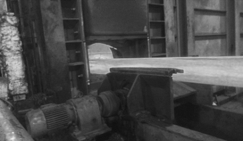
Figure 1. View of an industrial recuperator in a steelworks
The heat contained in exhaust gases is mainly used to heat up the combustion air in recuperators [19, 20] (Figure 1).
Figure 2. Possibilities of reducing fuel consumption through recuperation [19, 21]
When natural gas is used in a furnace, a heated air temperature of 600℃ saves 32.5% of fuel when the exhaust gas temperature is 1000℃. If the exhaust gas temperature is 800℃ and the heated air temperature is 500℃, the fuel saving is 24% (Figure 2) [7, 19, 21]. Theoretical calculations for two-stage steel briquette heating confirm that using combustion air at 600℃ reduces specific heat consumption and heating costs by about 28% [22]. The use of recovery also reduces pollutant emissions, i.e., an ecological effect [23].
Recuperators operate continuously. The hot flue gases and the heated gas medium flow simultaneously through separate channels, and the heat exchange takes place through the walls separating their streams. Recuperators can be made of metal or ceramic. Metal recuperators, most often used for heating furnaces, are made of heat-resistant steel. Their operating temperatures can range from 450 to 900℃ [24]. This causes restrictions in the flow of flue gases with a temperature above 900℃. The use of ceramic recuperators requires much more space in the production hall and is much more expensive.
In the case of recuperation, there are therefore temperature limitations. On the one hand, a certain flue gas temperature specified for a given recuperator cannot be exceeded, as this could damage the recuperator. If the temperature exceeds the permissible value, then the flue gases are cooled before entering the recuperator. On the other hand, there may also be a limitation of the air heating temperature caused by the materials used in the burners.
In addition, recuperators, like any device, must be periodically inspected and repaired. It is also important to clean recuperators to ensure the best quality of heat exchange surfaces.
Significant savings can be made in heating steel charge by using the enthalpy of the charge entering the furnace (Figure 3). Charges with a higher temperature, up to about 700℃, can be transferred directly from the COS line to the furnace. This makes it possible to achieve technological heating conditions in about 50% less time [19].
Figure 3. Hot charge entering the furnace
Continuous casting of steel (COS) technology guarantees low costs and high quality of steel production. This process consists in supplying liquid steel to a water-cooled crystallizer with a suitable cross-section. The material from the steel ladle is poured into the tundish, which is a tank that ensures constant ferrostatic pressure of the steel. In the crystallizer, the steel solidifies, and after leaving it is cooled with water, then it goes to the roller table, where it is cut to the appropriate length using gas-air burners. This process produces semi-finished products whose cross-section corresponds to traditional ingots pre-processed into flat, rectangular and square cross-sections. The use of this method of steel casting allows for the elimination of such operations from steel production as: casting steel into ingot moulds, heating ingots in pit furnaces and preliminary rolling in a crusher type rolling mill. As a result of this solution, the energy consumption of steel production and its production costs are reduced, and the proper selection of COS parameters allows the production of semi-finished products without surface and internal defects. The most important advantages of continuous casting of steel include the elimination of long-term and costly heating of ingots [25].
When calculating the economic impact of using heat from hot charge, the primary consideration is the fuel savings in the furnaces, which are directly reflected in the unit value of heat consumption. The use of hot charge enthalpy in the heating process can reduce specific heat consumption by about 25% [21]. Studies at Mobareke Steel Company show that hot charging can reduce energy consumption by 40% [26].
The possibilities associated with hot charge heating are also described in the study [27].
Heating the hot charge requires adapting the heating furnace and its fittings to much higher temperatures than in the case of the cold charge. First of all, a new charge heating technology dependent on the charge temperature at the entrance to the furnace should be implemented. The heating curves must correspond to the initial charge temperature measurement signal before entering the kiln. In addition, a number of protection devices, instruments and furnace fittings against high temperatures should be introduced. The high-temperature radiant charge could damage electrical wiring, plumbing, and other kiln instrumentation. It is therefore necessary to adequately insulate all kiln auxiliary equipment exposed to high temperatures.
In the paper, in order to improve the economic efficiency of steel charge preheating technology, a walking beam furnace (furnace No. 1) and a pusher furnace (furnace No. 2) were subjected to analysis of the possibility of using exhaust waste heat. These are the two types of furnaces most commonly used in rolling mill departments in steelworks. These furnaces are used to heat steel charge. In this case, the source of heat is the combustion of natural gas. Characteristic data for the analyzed units are presented in Table 1.
The list of parameters of the furnaces allows for a possible analysis of their impact on possible savings in fuel consumption in the context of the calculations carried out.
Table 1. List of parameters of analyzed furnaces
|
Characteristic parameter |
Furnace No. 1 |
Furnace No. 2 |
|
Nature of continuous |
work |
work |
|
The furnace is designated |
for heating the charge before rolling |
for heating the charge before rolling |
|
Fuel type |
natural gas PN-C-04753-E (formerly GZ-50) |
natural gas PN-C-04753-E (formerly GZ-50) |
|
Initial charge temperature, ℃ |
20; 300; 400; 500; 600; 700 |
20; 300; 400; 500; 600; 700 |
|
Final charge temperature, ℃ |
1180 |
1250 |
|
Final temperature difference in cross-section, K |
50 |
50 |
|
Type of heated charge |
medium carbon steel |
medium carbon steel |
|
Dimensions of heated charge |
160x160x14000 |
250x250x3400 |
|
Number of pieces of charge in furnace |
70 |
176 |
|
Unit weight of heated charge, kg |
3000 |
1670 |
|
Total weight of heated charge in furnace, t |
210 |
294 |
|
Average time of charge heating, min |
71 |
176 |
|
Average furnace efficiency, t/h |
175 |
100 |
|
Outer surface area of furnace, m2 |
1004 |
740 |
|
The temperature of exhaust exiting the furnace, ℃ |
830 |
950 |
|
Average outside furnace temperature, ℃ |
126 |
150 |
|
Average ambient furnace temperature, ℃ |
28 |
30 |
The following composition of natural gas supplied to the heating furnaces was used for the calculations: CH4 - 95.5%; C2H6 - 1.4%; C3H8 - 0.2%; N2 - 2.9%. It was assumed that the combustion process is carried out with the value of excess air ratio λ = 1.05. Combustion calculations were carried out using an authorial computer program.
The computer calculation program "Program for calculations of gas combustion with excess air" allows to determine the basic values characteristic for the combustion of gaseous fuels with the value of the ratio of excess air λ≥1.0. The program was created for calculations related to didactic activity at the Faculty of Production Engineering and Materials Technology of the Częstochowa University of Technology, but it can also be used for simple calculations in research work.
The scheme of the calculation methodology is presented in Figure 4 and described in detail in study [8].
Figure 4. Scheme of the calculation method
Based on the dependencies concerning the combustion process and those related to heat losses to the environment, the values presented in Table 2 were determined.
Summary of results of specific heat of steel charge and useful heat of steel charge presented in Table 3.
The specific combustion air and exhaust gas temperature was calculated for varying combustion air temperatures. The results are presented in Table 4.
In accordance with the adopted scheme, the gas stream, the chemical heat of the gas, the physical heat of the combustion air and the heat losses with the exhaust gases were determined for the variable values of the combustion air temperature and for different charge temperatures at the entrance to the furnace. The results are summarized in Tables 5-10.
Table 2. Calculation results concerning the combustion process and heat losses to the environment
|
Actual Combustion Air Demand, m3 p/ m3 g |
Volume of Humid Exhaust Gas Generated in the Combustion Process, m3 sp/ m3 g |
Calorific Value of Fuel, J/m3 |
Coefficient of Heat Transfer through the Walls and Ceiling, W/(m2 . K) |
Heat Losses to the Environment, W |
|
Furnace No. 1 |
||||
|
9.845 |
10.854 |
34851000 |
12.418 |
1221831,86 |
|
Furnace No. 2 |
||||
|
9.845 |
10.854 |
34851000 |
13.450 |
1194360,00 |
Table 3. Summary of results of specific heat of steel charge and useful heat of steel charge
|
Initial Temperature of Charge Entering Furnace, ℃ |
Specific Heat of Steel Charge, J/(kg. K) |
Useful Heat of Steel Charge, W |
|
Furnace No. 1 |
||
|
20 |
549 |
30964654,86 |
|
300 |
600 |
25664345,33 |
|
400 |
605 |
22942507,33 |
|
500 |
618 |
20416397,43 |
|
600 |
637 |
17960378,42 |
|
700 |
659 |
15376147,08 |
|
Furnace No. 2 |
||
|
20 |
554 |
18948050,46 |
|
300 |
605 |
15975864,07 |
|
400 |
611 |
14415364,24 |
|
500 |
623 |
12981170,07 |
|
600 |
642 |
11600289,83 |
|
700 |
664 |
10151154,96 |
Table 4. Summary of results of specific heat of combustion air and gas exhaust
|
Combustion Air Temperature, °C |
Specific Heat of Combustion Air, J/(m 3. K) |
Specific Heat of Gas Exhaust, J/(m 3. K) |
|
20 |
1290 |
1359 |
|
300 |
1322 |
1417 |
|
400 |
1334 |
1442 |
|
500 |
1346 |
1469 |
|
600 |
1358 |
1498 |
|
700 |
1369 |
1529 |
Table 5. Summary of results of gas stream, chemical gas heat, physical heat of combustion air and heat loss of the exhaust gases for charge temperature at the furnace inlet 20℃
|
Combustion Air Temperature, ℃ |
Gas Stream, m3 /s |
Chemical Gas Heat, W |
Physical Heat of Combustion air, W |
Heat Loss of the Exhaust Gases, W |
|
Furnace No. 1 |
||||
|
20 |
1.892 |
65940820,95 |
480589,78 |
23164688,90 |
|
300 |
1.648 |
57434038,01 |
6434614,56 |
21037390,43 |
|
400 |
1.575 |
54907358,56 |
8276502,47 |
20466730,80 |
|
500 |
1.509 |
52589498,59 |
9998033,11 |
19969789,70 |
|
600 |
1.448 |
50455608,90 |
11613441,81 |
19537722,21 |
|
700 |
1.392 |
48496670,67 |
13128463,15 |
19167791,47 |
|
Furnace No. 2 |
||||
|
20 |
1.322 |
46058529,21 |
335683,70 |
18519433,63 |
|
300 |
1.139 |
39693343,52 |
4447038,29 |
16641241,05 |
|
400 |
1.086 |
37840005,98 |
5703842,09 |
16144129,60 |
|
500 |
1.037 |
36153754,29 |
6873357,65 |
15713516,15 |
|
600 |
0.993 |
34612970,41 |
7966918,38 |
15340830,20 |
|
700 |
0.953 |
33208631,13 |
8989860,21 |
15022998,99 |
Table 6. Summary of results of gas stream, chemical gas heat, physical heat of combustion air and heat loss of the exhaust gases for charge temperature at the furnace inlet 300℃
|
Combustion Air Temperature, ℃ |
Gas Stream, m3 /s |
Chemical Gas Heat, W |
Physical Heat of Combustion air, W |
Heat Loss of the Exhaust Gases, W |
|
Furnace No. 1 |
||||
|
20 |
1.581 |
55082016,62 |
401448,66 |
19350043,88 |
|
300 |
1.377 |
47976088,11 |
5374994,44 |
17573058,28 |
|
400 |
1.316 |
45865489,59 |
6913569,47 |
17096372,02 |
|
500 |
1.260 |
43929323,19 |
8351607,06 |
16681264,69 |
|
600 |
1.209 |
42146831,78 |
9700998,35 |
16320347,91 |
|
700 |
1.162 |
40510481,69 |
10966533,55 |
16011335,51 |
|
Furnace No. 2 |
||||
|
20 |
1.127 |
39262195,97 |
286150,67 |
15786731,47 |
|
300 |
0.971 |
33836248,33 |
3790839,44 |
14185682,40 |
|
400 |
0.926 |
32256386,73 |
4862190,99 |
13761924,03 |
|
500 |
0.884 |
30818956,02 |
5859134,45 |
13394851,32 |
|
600 |
0.847 |
29505528,09 |
6791330,86 |
13077158,39 |
|
700 |
0.812 |
28308411,18 |
7663328,80 |
12806225,92 |
Table 7. Summary of results of gas stream, chemical gas heat, physical heat of combustion air and heat loss of the exhaust gases for charge temperature at the furnace inlet 400℃
|
Combustion Air Temperature, ℃ |
Gas Stream, m3 /s |
Chemical Gas Heat, W |
Physical Heat of Combustion air, W |
Heat Loss of the Exhaust Gases, W |
|
Furnace No. 1 |
||||
|
20 |
1.420 |
49505756,18 |
360807,77 |
17391130,78 |
|
300 |
1.237 |
43119200,54 |
4830853,71 |
15794039,36 |
|
400 |
1.183 |
41222269,69 |
6213670,18 |
15365610,72 |
|
500 |
1.133 |
39482112,25 |
7506127,20 |
14992527,02 |
|
600 |
1.087 |
37880072,40 |
8718912,06 |
14668147,87 |
|
700 |
1.045 |
36409379,18 |
9856330,06 |
14390418,52 |
|
Furnace No. 2 |
||||
|
20 |
1.024 |
35693887,9 |
260144,13 |
14351969,08 |
|
300 |
0.883 |
30761072,4 |
3446312,52 |
12896429,87 |
|
400 |
0.841 |
29324795,1 |
4420295,29 |
12511184,38 |
|
500 |
0.804 |
28018003,9 |
5326632,47 |
12177472,73 |
|
600 |
0.770 |
26823945,6 |
6174107,08 |
11888653,03 |
|
700 |
0.738 |
25735627,6 |
6966854,30 |
11642344,00 |
Table 8. Summary of results of gas stream, chemical gas heat, physical heat of combustion air and heat loss of the exhaust gases for charge temperature at the furnace inlet 500℃
|
Combustion Air Temperature, ℃ |
Gas Stream, m3 /s |
Chemical Gas Heat, W |
Physical Heat of Combustion air, W |
Heat Loss of the Exhaust Gases, W |
|
Furnace No. 1 |
||||
|
20 |
1.272 |
44330486,13 |
323089,37 |
15573083,64 |
|
300 |
1.108 |
38611573,05 |
4325842,29 |
14142950,17 |
|
400 |
1.059 |
36912945,00 |
5564100,85 |
13759308,92 |
|
500 |
1.014 |
35354701,44 |
6721446,01 |
13425226,93 |
|
600 |
0.973 |
33920136,85 |
7807447,86 |
13134757,97 |
|
700 |
0.936 |
32603188,06 |
8825961,60 |
12886062,10 |
|
Furnace No. 2 |
||||
|
20 |
0.930 |
32414395,84 |
236242,55 |
13033335,25 |
|
300 |
0.802 |
27934798,85 |
3129671,35 |
11711528,44 |
|
400 |
0.764 |
26630484,15 |
4014166,29 |
11361678,63 |
|
500 |
0.730 |
25443758,68 |
4837230,79 |
11058627,82 |
|
600 |
0.699 |
24359408,42 |
5606840,91 |
10796344,37 |
|
700 |
0.671 |
23371083,12 |
6326751,91 |
10572665,79 |
Table 9. Summary of results of gas stream, chemical gas heat, physical heat of combustion air and heat loss of the exhaust gases for charge temperature at the furnace inlet 600℃
|
Combustion Air Temperature, ℃ |
Gas Stream, m3 /s |
Chemical Gas Heat, W |
Physical Heat of Combustion air, W |
Heat Loss of the Exhaust Gases, W |
|
Furnace No. 1 |
||||
|
20 |
1.128 |
39298812,09 |
286417,54 |
13805481,08 |
|
300 |
0.982 |
34229016,79 |
3834843,20 |
12537673,04 |
|
400 |
0.939 |
32723189,29 |
4932554,83 |
12197576,50 |
|
500 |
0.899 |
31341812,14 |
5958537,05 |
11901414,05 |
|
600 |
0.863 |
30070075,93 |
6921273,67 |
11643914,39 |
|
700 |
0.829 |
28902605,70 |
7824182,33 |
11423446,42 |
|
Furnace No. 2 |
||||
|
20 |
0.839 |
29256813,84 |
213229,46 |
11763719,58 |
|
300 |
0.723 |
25213587,62 |
2824800,83 |
10570673,87 |
|
400 |
0.690 |
24036330,07 |
3623134,50 |
10254903,97 |
|
500 |
0.659 |
22965207,03 |
4366021,86 |
9981374,24 |
|
600 |
0.631 |
21986486,52 |
5060661,99 |
9744640,59 |
|
700 |
0.605 |
21094436,91 |
5710444,32 |
9542751,20 |
From Table 3, it can be seen for both furnaces that the useful heat of the charge decreases as the initial temperature of the charge at the furnace inlet (t'w) increases. By analyzing Tables 5-10, it can be observed that as the combustion air temperature (tp) increases, the physical heat of the combustion air increases, and the heat loss carried by the flue gas decreases. As the combustion air temperature (tp) increases steadily, the chemical heat of the fuel at the furnace entrance (t'w) decreases. This is due to a reduction in gas consumption.
Summary calculations were also performed for both furnaces on the effects of furnace inlet charge temperature and combustion air temperature on the fuel consumption rate (Figures 5 and 6). A conversion factor of E=10.972 was used for the calculations based on the standard heat of combustion of natural gas [28].
The heating cost per 1t of steel was calculated assuming a gas price of PLN 0.1094 per kWh [8]. The results are presented in Figures 7 and 8.
Table 10. Summary of results of gas stream, chemical gas heat, physical heat of combustion air and heat loss of the exhaust gases for charge temperature at the furnace inlet 700℃
|
Combustion Air Temperature, ℃ |
Gas Stream, m3 /s |
Chemical Gas Heat, W |
Physical Heat of Combustion air, W |
Heat Loss of the Exhaust Gases, W |
|
Furnace No. 1 |
||||
|
20 |
0/976 |
34004467,99 |
247831,31 |
11945603,81 |
|
300 |
0/850 |
29617676,56 |
3318212,33 |
10848595,14 |
|
400 |
0.812 |
28314714,46 |
4268040,03 |
10554316,47 |
|
500 |
0.778 |
27119436,72 |
5155801,70 |
10298053,08 |
|
600 |
0.747 |
26019029,08 |
5988838,24 |
10075243,83 |
|
700 |
0.718 |
25008840,68 |
6770106,87 |
9884477,35 |
|
Furnace No. 2 |
||||
|
20 |
0.744 |
25943157,8 |
189078,88 |
10431348,90 |
|
300 |
0.642 |
22357871,4 |
2504861,05 |
9373428,75 |
|
400 |
0.612 |
21313951,2 |
3212774,65 |
9093423,26 |
|
500 |
0.584 |
20364144,6 |
3871521,84 |
8850873,78 |
|
600 |
0.559 |
19496275 |
4487486,33 |
8640952,82 |
|
700 |
0.537 |
18705259,8 |
5063673,67 |
8461929,62 |
Figure 5. Effect of furnace inlet charge temperature and combustion air temperature on the fuel consumption meter - furnace No. 1
Analyzing Figure 5 and Figure 6, it can be observed that as combustion air temperature (tp) increases, the fuel consumption index (Wz) decreases. It also decreases with an increase in the initial temperature of the charge at the furnace inlet (t'w).
If reference temperatures of tp =20℃ and t'w =20℃, are assumed, then:
Figure 6. Influence of furnace inlet charge temperature and combustion air temperature on the fuel consumption indicator - furnace No. 2
On the other hand, assuming reference temperatures of tp=400℃ and t'w =400℃, then heating the air to tp =700℃ and heating the load by t'w =700℃ results in a reduction of the fuel consumption rate Wz by 103 kWh/t for furnace 1 and by 120 kWh/t for furnace 2.
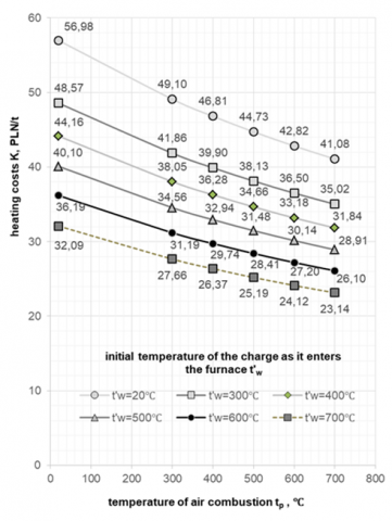
By analyzing Figure 7 and Figure 8, it can be concluded that combustion air temperature increases (tp) the heating costs (K) decrease. They also decrease as the initial charge temperature at the furnace inlet (t'w) increases.
Assuming reference temperatures of tp =20℃ and t'w =20℃, then:
Figure 7. Effect of furnace inlet charge temperature and combustion air temperature on heating costs - furnace No. 1
Assuming, in turn, the reference temperatures at tp =400℃ and t'w =400℃, then heating the air to tp =700℃ and heating the charge by t'w =700℃ results in a reduction of the heating cost K by PLN 11.33/t for furnace no. 1 and by PLN 13.14/t for furnace no. 2.
The study also determined the savings resulting from the use of heated combustion air and/or the use of hot charge. It was assumed that furnace No. 1 heats 600,000 tons of feedstock per year, while furnace No. 2 heats 400,000 tons of feedstock per year.
For a reference temperature of tp =20℃ and t'w =20℃, then:
Assuming, in turn, reference temperatures of tp =400℃ and t'w=400℃, then heating the air to tp =700℃ and heating the charge by t'w =700℃ results in annual savings of PLN 6.80 million for furnace no. 1 and PLN 5.26 million for furnace no. 2.
Figure 8. Effect of furnace inlet charge temperature and combustion air temperature on heating costs - furnace No. 2
Steelworks use large amounts of energy from gaseous fuel to heat the charge before rolling. Given the current geopolitical and economic situation on the gas market, all solutions to reduce gas consumption should be sought at this time.
Analyzing the results of the calculations, it can be concluded that using recuperation and hot charging enthalpy will significantly reduce fuel consumption and thus bring economic and environmental savings. The selected options (reference temperatures tp =20℃ and t'w =20℃), it is possible to reduce the fuel consumption index (Wz) and heating costs (K):
As gas prices are expected to continue to rise (up to 400-1000%), different fuel-saving options should be analyzed. Other considerations could include replacing air with oxygen in the combustion process or removing the reheating furnaces, and feeding the mill charge directly from the COS.
The considerations carried out in the work show that the use of recuperation and hot charge brings the expected effect in the form of reducing fuel consumption. The results of individual balance calculations show that with the increase in the temperature of the heated air, the chemical heat supplied to the furnace decreases, because it is replaced by the physical heat of the air. In the case of an increase in the temperature of the charge at the entrance to the furnace, the chemical heat also decreases, because the temperature gradient by which the charge must be heated decreases.
A similar reduction is achieved in the case of gas consumption (Vg, m3).
The presented solutions can be successfully used in steelworks. In many steelworks, they are already used, but not on such a large scale, because the temperature limitations regarding recuperation prevent the full use of exhaust gas waste heat. In the case of using a hot charge, such solutions also work, but due to the small capacity of the steel plant, and thus also the COS, the enthalpy of the hot charge cannot be used to the full extent. A certain limitation here is also the transport of hot charge and temperature losses of the charge during transport. Further research work should be aimed at solving the problems limiting the presented trends in fuel consumption reduction.
It should also be remembered that the natural gas in question consists mainly of hydrocarbons, the combustion of which causes the release of CO2 into the atmosphere. Every 1 m3 of natural gas generates over 1 m3 of CO2, which means that by reducing gas consumption by an average of 50%, greenhouse gas emissions from the charge heating process are also reduced by 50%.
However, feeding the batch directly from COS is possible only with a long-term and unchanging assortment over time. Such solutions function in mini mills operating in the USA, where one assortment is rolled for at least several days. In Polish conditions, steel mills cannot afford such solutions, at least at present, hence the need to modify and improve the heating technology.
The introduction of oxycombustion, i.e., combustion with oxygen-enriched air, still requires much research. However, these are very difficult tasks to accomplish, if only due to the fact that every percentage of additional oxygen in the air raises the combustion temperature. Its uncontrolled growth may cause overheating of the charge or damage to the burners.
There are a number of problems in the steel industry that limit the possibilities of reducing fuel consumption, however, research should be successively conducted that will show specific economic and ecological benefits and will convince the steelworks authorities to new solutions.
[1] Chakravarty, K., Kumar, S. (2020). Increase in energy efficiency of a steel billet reheating furnace by heat balance study and process improvement. Energy Reports, 6: 343-349. https://doi.org/10.1016/j.egyr.2020.01.014
[2] Chen, D., Lu, B., Zhang, X., Dai, F., Chen, G., Liu, Y. (2018). Fluctuation characteristic of billet region gas consumption in reheating furnace based on energy apportionment model. Applied Thermal Engineering, 136: 152-160. https://doi.org/10.1016/j.applthermaleng.2018.03.007
[3] Ghanbari, H., Helle, M., Saxén, H. (2012). Process integration of steelmaking and methanol production for suppressing CO2 emissions—A study of different auxiliary fuels. Chemical Engineering and Processing: Process Intensification, 61: 58-68. https://doi.org/10.1016/j.cep.2012.06.008
[4] Neumann, K., Gladyszewski, K., Groß, K., Qammar, H., Wenzel, D., Górak, A., Skiborowski, M. (2018). A guide on the industrial application of rotating packed beds. Chemical Engineering Research and Design, 134: 443-462. https://doi.org/10.1016/j.cherd.2018.04.024
[5] Zaniewicz M. (2022). Perspectives of Russian gas blackmail towards the EU, PISM Bulletin No. 35 (2454) 23 February 2022. https://www.pism.pl/publikacje/perspektywy-rosyjskiego-szantazu-gazowego-wobec-ue, accessed on 12. Sep. 2022.
[6] Ruszel, M. (2017). Assessment of the security of natural gas supply to Poland - current state and perspective until 2025. Energy Policy Journal, 20(1): 5-22.
[7] Boryca J., Kolmasiak C., Wyleciał T., Urbaniak D. (2023). Effect of heating technology on scale adhesion in the steel charge heating process, Metalurgija, 3-4 (62) 3-4, 430-432. https://hrcak.srce.hr/clanak/434296
[8] Wyleciał, T., Boryca, J., Urbaniak, D. (2020). Use of exhaust waste energy as essential element of heat economy in furnaces heating steel charge. In: Wróbel, M., Jewiarz, M., Szlęk, A. (eds) Renewable Energy Sources: Engineering, Technology, Innovation. Springer Proceedings in Energy. Springer, Cham. https://doi.org/10.1007/978-3-030-13888-2_102
[9] Boryca, J., Wyleciał, T., Urbaniak, D. (2022). Influence of Initial Charge Temperature and Furnace Exploitation on Steel Loss. Archives of Metallurgy and Materials, 67(1): 289-291. https://doi.org/10.24425/amm.2022.137504
[10] Hadała, B., Rywotycki, M., Malinowski, Z., Kajpust, S., Misiowiec, S. (2021). Optimization of long charge heating in a rotary furnace. Archives of Metallurgy and Materials, 66(2): 659-668. https://doi.org/10.24425/amm.2021.135904
[11] Gołdasz, A., Malinowski, Z., Telejko, T., Rywotycki, M., Szajding, A. (2012). The influence of radiation model on the distribution of heat flux in the pusher furnace. Archives of Metallurgy and Materials, 57: 1143-1149. https://doi.org/10.2478/v10172-012-0128-y
[12] Gołdasz, A., Malinowski, Z. (2016). Heat flux identification at the charge surface during heating in chamber furnace. Archives of Metallurgy and Materials, 61(4): 2021-2026. https://doi.org/10.1515/amm-2016-0326
[13] Gołdasz, A., Malinowski, Z. (2017). Identification of the heat transfer coefficient at the charge surface heated on the chamber furnace. Archives of Metallurgy and Materials, 62(2): 509-513. https://doi.org/10.1515/amm-2017-0075
[14] Boryca, J., Kieloch, M. (2006). Investigation of the adhesion of scale forming in the process of steel charge heating before plastic working. Archives of Metallurgy and Materials, 51(3): 451-457.
[15] Kieloch, M., Piechowicz, Ł., Boryca, J. (2007). Correlation between heat consumption and steel loss for scale in the two-stage heating process. Archives of Metallurgy and Materials, 52(4): 655-663.
[16] Kieloch, M., Piechowicz, Ł., Boryca, J., Klos, A. (2010). Numerical analysis of correlation between heat consumption and the steel loss for scale in the charge heating process. Archives of Metallurgy and Materials, 55(3): 647-656.
[17] Sarani, N.A., Hashim, A.A., Kadir, A.A., Hissham, N.F.N., Hassan, M.I.H., Nabiałek, M., Jeż, B. (2022). Assessment on the physical, mechanical properties and leaching behaviour of fired clay brick incorporated with steel mill sludge. Archives of Metallurgy and Materials, 67(1): 209-214. https://doi.org/10.24425/amm.2022.137491
[18] Papadatu, C.P., Sandu, I. G., Bordei, M., Nabialek, M., Sandu, A.V. (2016). Influence of the cooling regime on the characteristics of plasticity in the case of steel for metal structures. Materiale Plastice, 53(4): 771-775.
[19] Wyleciał T., Boryca J., Urbaniak D. (2023). Analysis of the effect of the excess air combustion ration the loss of steel and scale adhesion in the process of heating the steel charge including changes in technology. Archives of Metallurgy and Materials, 68(3): 1025-1028. https://doi.org/10.24425/amm.2023.145470
[20] Preheated Combustion Air, Energy Tips - Process Heating, Process Heating Tip Sheet #1 - November 2007. https://www.google.com/url?sa=t&rct=j&q=&esrc=s&source=web&cd=&ved=2ahUKEwjtlKDRgJH6AhXjQ_EDHZLvBeIQFnoCAgQAQ&url=https%3A%2F%2Fenergy.gov%2Fsites%2Fprod%2Ffiles%2F2014%2F05%2Ff16%2Fet_preheated.pdf&usg=AOvVaw0MQAVECo8Fzevs-eRcx-az, accessed on 13. Sep. 2022.
[21] Kieloch M., Boryca J., Piechowicz Ł. (2006). Modelowanie pracy cieplnej pieców grzewczych w dwuetapowym procesie nagrzewania, Hutnik –Wiadomości Hutnicze 7(73), 351-357. https://sigma-not.pl/publikacja-16947-modelowanie-pracy-cieplnej-piec%C3%B3w-grzewczych-w-dwuetapowym-procesie-nagrzewania-hutnik-2006-7.html
[22] Mallela, G., Paturu, P., Paleti, K., Komaleswararao, M., Sharma, S., Vardhan, G.H. (2021). Thermal efficiency and heat balance of reheating furnace of rolling mills, International Journal of Ambient Energy, 7(42): 758-763. https://doi.org/10.1080/01430750.2018.1563819
[23] Benchmarking energy intensity in the Canadian steel industry, Her Majesty the Queen in Right of Canada, 2007. https://natural-resources.canada.ca/sites/www.nrcan.gc.ca/files/oee/files/pdf/industrial/SteelBenchmarkEnglish.pdf.
[24] Piech J. (2001). Piece ceramiczne i szklarskie, Wyd. AGH, Kraków 2001. https://winntbg.bg.agh.edu.pl/skrypty2/0063/index.php.
[25] Pater Z. (2014). Podstawy metalurgii i odlewnictwa. Wyd. Politechniki Lubelskiej, Lublin 2014. https://bc.pollub.pl/dlibra/docmetadata?showContent=true&id=8711.
[26] Shamanian, M., Najafizadeh, A. (2004). Hot charge of continuously cast slabs in reheating furnaces. International Journal of Iron & Steel Society of Iran, 1(1): 35-37.
[27] Dai, J. (2017). Hot charging and transporting to continuous discussion on casting slab at Tanggang. In MATEC Web of Conferences, 100: 05082. https://doi.org/10.1051/matecconf/201710005082
[28] https://www.rachuneo.pl/artykuly/ile-kosztuje-gaz-ziemny, accessed on 13. Sept. 2022.