Asseel M. Rasheed Al-Gaheeshi![]() | Farhan Lafta Rashid*
| Farhan Lafta Rashid*![]() | Muhammad Asmail Eleiwi
| Muhammad Asmail Eleiwi![]() | Ali Basem
| Ali Basem![]()
© 2023 IIETA. This article is published by IIETA and is licensed under the CC BY 4.0 license (http://creativecommons.org/licenses/by/4.0/).
OPEN ACCESS
The thermo-hydraulic analysis of laminar mixed convection (forced and natural) through a horizontal channel-enclosure assembly equipped with a heated hollow hemispherical source (constant power of 20 W) in the bottom of the enclosure and different inlet air velocities equivalent to Reynolds number ranged (2.8814, 14.407, 28.814, and 43.221) are obtained numerically with the help of COMSOL Program. The impact of altering the input air velocity on the thermo-hydraulic properties is explored here as part of the research project. Good agreement was found between the derived numerical findings and those already established in the literature. The pressure profile throughout the channel is not altered via the numerically simulated increase on the positive y-axis. Increasing the incoming air velocity increases the natural convection induced via the heated source, which in turn increases the blending of cold and hot air within the enclosure and reduces the temperature gradient across the channel. As a result of the circumstances preventing slippage, the channel area exhibits the characteristic velocity profile of laminar flow, which consists of zero velocity at the channel walls and the maximum velocity in the channel's middle. The area of the recirculating streamlines is expanded by the rise in the velocity of intake air. As the incoming air velocity increases, so does the average Nusselt number.
open enclosure, heated source, mixed convection, forced convection, natural convection
In the latter half of the 20th century, one of the open cavities most often employed uses on tiny scales was the cooling of electronic components. It is easy to maintain and has a straightforward design that makes it simple to use. The analysis focused on the effects of mixed and natural convection on the flow behavior while taking into account the electronic component as the heat source. And, the location of heated wall or circuit board within the housing determined its classification [1, 2]. This determined which of the (3) classifications it belonged to. The cavities that are occupied by fluid are necessary constituents in a broad diversity of engineering and geophysical regimes, making the mixed convection problem in the cavities too pertinent in the modern world. And, the flow and heat transport within a hollow vary significantly from the mixed convection boundary layer outside [3]. Mixed convection develops in a hollow due to the complex interplay between several small fluid systems that being in thermal contact with the whole surrounding walls. One such analogy is a thermal feedback loop including this relationship. The complexity of the interaction occurring in a cavity affects directly the range of possible flows that may occur within that cavity. Mixed convection is a phenomenon that takes place in cavities and is affected by their form and orientation. According to the possible applications in engineering, the cavity phenomena may be roughly divided into two categories [4-7].
Fu et al. [8] performed a numerical study to investigate the heat transfer mechanisms in a fluid-cooled reciprocating channel. The moving boundary problem of the reciprocating piston is then resolved using the random Largragian-Eulerian Kinematics technique as well as Finite Element Method. The thermal stratification layers are greatly impacted by the size ratio of (Gr/Re2), which possesses an instant effect upon the mechanisms of heat transport. And, in an open chamber having a heated wall and a horizontally insulated plate, Saha et al. [9] studied the phenomena of mixed convection. Considered are three fundamental heating configurations: (1) the wall that is heated is the surface that is horizontal inside the hollow, (2) the inflow side is where the heated wall which is (assisting flow), and (3) the side opposite the outflow is where the heated wall is located (opposing flow). The most recent research indicates that when Richardson and Reynolds numbers increase, the values of the maximum temperature decrease. The ratio of H/D is shown to have an important effect upon the streamline as well as the isotherm patterns under a variety of heating conditions. With the use of computational techniques, Aylı [10] described the properties of the heat transfer of a laminar-coupled forced convection via a horizontal duct. And, the investigation is done into how the cavity's geometrical characteristics and Reynolds number affect heat transmission. The generated model of the adaptive neuro-fuzzy interface regime has (R2=0.9983) and a (1.07%) mean percentage error when predicting the Nusselt number. The influences of different training approaches are studied, as is their capacity for forecasting the distribution of Nusselt number (Nu). Ozgen and Varol [11] investigated the mixed convection heat transfer in a horizontal duct having a porous medium since it's important for many technical applications, such as the flow of fluid in the geothermal resources, radioactive nuclear waste material storage, cooling, and chemical industry creations. Using the Finite Difference Method, those equations in dimensionless form have been solved for a variety of different values of the parameters. The temperature and flow fields are impacted by variables like the Peclet and Rayleigh numbers. Laouira et al. [12] conducted a statistical analysis to evaluate the heat transmission in a horizontal channel with an open trapezoidal enclosure that is subjected to a heat source of varying lengths. The source of heat is thought to be a local heating element that may be any length and being imbedded in the enclosure's bottom wall. The temperature of this element is maintained at a constant level. A further observation that was made was that an increase in the length of the local heat source led to an increase in the average and local Nusselt values. Additionally, the maximum temperature is near the position of the source of heat. In a limited-length horizontal channel with an aspect ratio of 10, combined (mixed) convection was presented statistically by Bahlaoui et al. [13]. And, the cooling medium, the air with a (0.72) Pr, is regarded as radiation transparent. The channel is insulated from above and quietly heated from below, for various governing parameter combinations, surface emissivity (0.1), Rayleigh number (104≤Ra≤8×10⁵), and Reynolds number (3≤Re≤1,000), total radiative and convective Nu, and the distribution of temperature. The findings point to the existence of two zones of flow, each of which is controlled via a different group of regulating elements. In a three-dimensional vented cavity that being separately heated, Doghmi et al. [14] carried out a numerical analysis of the mixed convection. The authors used the finite volume technique. And, the mean Nu, the distribution of temperature, and the streamlines are presented for a values' range for the thermal regulating parameters, noticeably the Richardson and Reynolds numbers. According to the findings of computer analysis, the aforesaid factors significantly affect how quickly heat is transmitted. Many scholars [15-30] published their findings on the influence that various factors have on mixed convection heat transfer, natural convection, forced convection, and how it works.
The primary goals of this research were (1) to establish a baseline for a problem involving a channel-square enclosure assembly with a hemispherical heated source at the bottom, and (2) to provide light on the underlying problem mechanics. The writers have looked through the relevant literature, and to the best of their knowledge, this issue seems to be the most common one that they have uncovered. These two objectives are planned to be completed in an efficient manner.
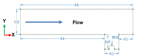
The design shown in Figure 1 depicts a horizontal channel having an open square enclosure and a hemispherical heating source. And, a duct connected to a square, open enclosure regulates the flow of air and hence the movement. The enclosure has a height of 0.12 m. It is assumed that the free length of the channel extends beyond the hollow is 0.6 m. And, the heat source radius, which is (0.02 m) and incorporated into the enclosure's bottom wall. Twenty watts of electricity are always delivered. As the ambient air at (20℃) flows into horizontal channel, the remaining walls are assumed to be adiabatic. The enclosure width is (0.1 m), and the height is (0.07 m). Table 1 presents the whole required values in case study.
Table 1. Geometric requirements and fluid dynamics variables
|
Symbol |
Value |
Description |
|
D |
12 cm |
Tube diameter |
|
L |
80 cm |
Tube length |
|
W |
10 cm |
Enclosure width |
|
H |
7 cm |
Enclosure height |
|
r |
2 cm |
Radius of the sphere enclosing the heat source |
|
Tin |
20℃ |
Inlet flow temperature |
|
Vin |
0.1–1.5 m/s |
Intake air velocity |
|
Re |
2.8814–43.221 |
Reynolds number at the inlet |
|
Pw |
20 W |
Heat power source in enclosure |
Figure 1. Schematic of the case study with geometric dimensions
2.1 The fundamental equations
The fundamental equations that control the system have been rephrased and presented in Cartesian coordinates as follows [31-34]:
The equation of continuity:
$\frac{\partial(\rho U)}{\partial X}+\frac{\partial(\rho V)}{\partial X}=-\frac{\partial \rho}{\partial t}$ (1)
The equations describing the X-direction momentum conservation concept are as follows:
$\frac{d(\rho U)}{d \tau}+U \frac{\partial(\rho U)}{\partial X}+V \frac{\partial(\rho U)}{\partial Y}=-\frac{\partial P}{\partial X}+\frac{1}{R e_{i n}}\left(\frac{\partial^2 U}{\partial X^2}+\frac{\partial^2 U}{\partial Y^2}\right)$ (2)
So, for Y‐direction:
$\frac{d(\rho V)}{d \tau}+U \frac{\partial(\rho V)}{\partial X}+V \frac{\partial(\rho V)}{\partial Y}=-\frac{\partial P}{\partial Y}+\frac{1}{R e_{i n}}\left(\frac{\partial^2 V}{\partial X^2}+\frac{\partial^2 V}{\partial Y^2}\right)+\operatorname{Ri\theta }$ (3)
An expression of energy conservation is:
$\frac{d(\rho \theta)}{d \tau}+U \frac{\partial(\rho \theta)}{\partial X}+V \frac{\partial(\rho \theta)}{\partial Y}=\frac{1}{R e_{i n} \operatorname{Pr}}\left(\frac{\partial^2 \theta}{\partial X^2}+\frac{\partial^2 \theta}{\partial Y^2}\right)$ (4)
where:
$R e_{i n}=\frac{\rho u_{i n} H}{\mu}$ is the Reynolds no., where, H is the length of enclosure.
Richardson no. (Ri) can be expressed as: $R i=\frac{G r}{R e_{i n}^2}=\frac{g H \beta\left(T_h-T_c\right)}{u_{i n}^2}$.
The Prandtl number can be written as ${Pr}=\frac{v}{\alpha}$.
And, the dimensionless figure variables may be expressed as:
$\theta=\frac{T-T_C}{T_h-T_C}, U=\frac{u}{u_{i n}}, V=\frac{v}{u_{i n}}, X=\frac{x}{H}, Y=\frac{y}{H}, P=\frac{P}{\rho u_{i n}^2}$
where, H is the enclosure length. $\varepsilon=\frac{L_H}{H}$, where LH is the length of the heated source.
Nuavg is the average Nusselt number which may be predicted from:
$N_{a v g}=\frac{1}{L_H} \int_0^{L_H} N u(x) d Y$
And, in the overhead equation, Nu(x) is the local Nu.
$h(X)=\frac{Q}{T_h(X)-T_i}$
The assumptions in brief are laminar, incompressible flow, Newtonian fluid, 2-D, and the external force power is negligible.
2.2 Conditions for setting boundaries
The following boundary conditions have been presented below:
The inlet of channel [35-39]:
$X=0, H \leq Y \leq H+D, \theta=0, U_{i n}=1$
The exit of channel:
$X=0.8, H \leq Y \leq H+D, \frac{\partial \theta}{\partial X}=\frac{\partial U}{\partial X}=\frac{\partial V}{\partial X}=0, P=0$
On the heated source:
$\theta=1$, or,$\frac{\partial \theta}{\partial n}=0$, n is a perpendicular vector.
On the permanent partition:
$U=V=o$
2.3 Validation of the results
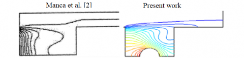
The prior instance, which being provided via Manca et al. [2], is again remedied via the program, as seen in the Figure 2, for producing a findings authentication for the current research. From the comparison, it can be seen that the two outcomes are in good agreement.
Figure 2. Manca et al.'s numerical study isotherm comparison [2]
There is a series of steps that have to be accomplished as well as verified prior the numerical simulation of present study can be run. When trying to condense these ideas, you should pay special attention to the following two aspects:
(1) Reducing the inaccuracy quantity into the numerical results, and it is possible to create the grids and analyze the density of the various components of the grids.
(2) Testing the efficacy of the used numerical model in producing reliable outcomes.
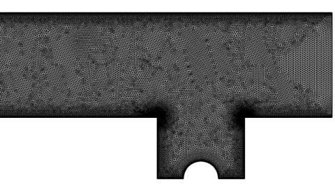
After completion, the grid structure may be seen in its complete form in Figure 3. In each example, the density of the components was deduced from the value of the ratio. The data from this study is shown in Table 2. In scenario 3, it is possible to conclude that the number of components is sufficient to give the necessary level of satisfaction. This process has been dubbed a grid independence test.
Table 2. Intake air velocity grid independence test for Re=2.8814
|
Component Density |
Case |
Total Cell Number |
Velocity (m/s) |
Difference % |
|
0.1 |
1 |
34157 |
0.07 |
0.23 |
|
2 |
150050 |
0.08 |
0.20 |
|
|
3 |
211300 |
0.09 |
0.08 |
|
|
4 |
292500 |
0.95 |
0.07 |
|
|
5 |
360010 |
0.10 |
0.07 |
|
|
0.2 |
1 |
24020 |
0.06 |
0.36 |
|
2 |
68340 |
0.07 |
0.22 |
|
|
3 |
137550 |
0.08 |
0.21 |
|
|
4 |
212200 |
0.90 |
0.20 |
|
|
5 |
283300 |
0.10 |
0.20 |
|
|
0.3 |
1 |
41170 |
0.07 |
0.30 |
|
2 |
61550 |
0.08 |
0.26 |
|
|
3 |
110200 |
0.09 |
0.24 |
|
|
4 |
182000 |
0.92 |
0.23 |
|
|
5 |
223000 |
0.10 |
0.23 |
Figure 3. Mesh generation
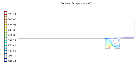
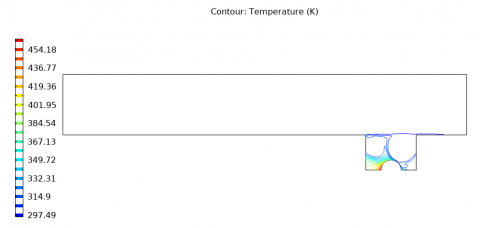
Figure 4 shows four isotherm contours with a heat source power of 20 W, corresponding to intake air velocities of 2.8814, 14.407, 28.814, and 43.221. In general, three main heat transport modes may be seen in various geographical locations. The mixed convection occurs into the interference zone between the enclosure and the channel. Because of the slow flow rate, the forced convection happens into the channel itself, while the diffusion happens in the bottom part of enclosure. These two processes are caused by the enclosure's design. Because of the moderately slow speed of the fluid and the moderately low intensity of heat source in the area of heat, the heat removal process in the majority of enclosure being characterized via the diffusion of heat. From the other hand, the process of heat removing in the zone of channel is dominated via the forced convection because of the relatively high velocities. Near the heat source within the enclosure, the zone of diffusive heat transmission is further limited. However, the channel and rest of enclosure's shapes show that convection is responsible for the bulk of heat evacuation. It is also clear that when one walks away from the channel and farther from the source of heat, the temperature starts to drop slowly. And, the problem's boundary condition is consistent with such result. This verified very well with study [40].
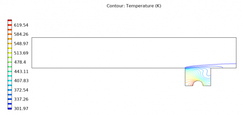
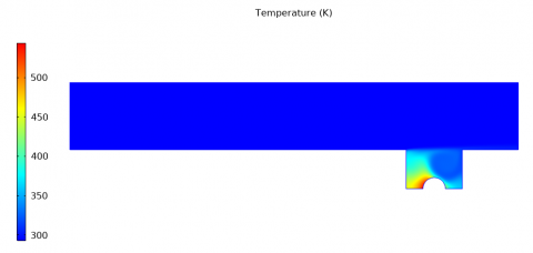
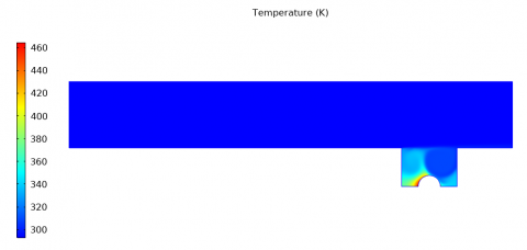
Figure 5 depicts four contours of temperature distribution for inlet air velocity equivalent to Reynolds number ranged (2.8814, 14.407, 28.814, and 43.221) with a heat source power of 20 W. There's a clear variation in the temperature and flow field within the square enclosure, as illustrated by these data. When the velocity of input air is increased, the temperature difference presence between the source of heat and the passage of channel gives rise to the natural as well as forced convection. Forced convection is caused by the flow of air that is moving upward through the enclosure, while the natural convection is caused via the temperature difference. More natural convection is going to be generated via the heated obstacle if the air entering the enclosure is moving faster. This means that there will be a greater mixing of cold and hot air, which will result in a further even distribution of temperature inside the enclosure. And, this verified very well with study [41].
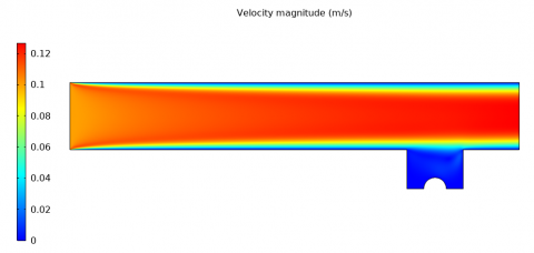
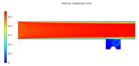
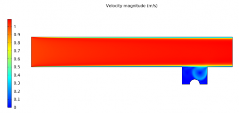
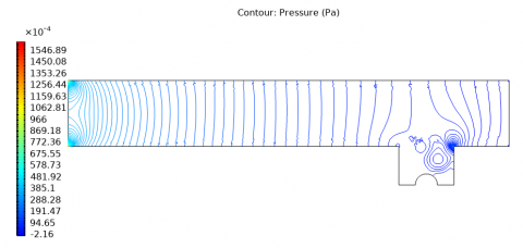
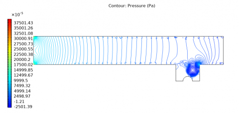
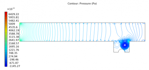
By a constant (20 W) power of the source of heat, the contours of velocity for various velocities of input air are shown in Figure 6. Because there is a heating source, there is an area in which the fluid is recirculating, and this region fills the whole enclosure. And, the presence of such area is a direct outcome of the presence of the source of heat. As a consequence of the buoyancy effect, the recirculating region of the enclosure is shifting to the left, towards the adiabatic wall of the cavity. Maximum velocity is seen in the channel's centre, with no velocity at the channel's sides owing to no-slip conditions, as is characteristic of laminar flow. Channel and top enclosure interference exposes a unique zone. Here, the channel's laminar velocity profile is altered via the enclosure's weakly re-circulating section. In Figure 7, one can see the streamline contours of pressure for the channel-enclosure system, making it easy to identify the re-circulating regions. The graph displays that the re-circulating streamlines area grows as the velocity of incoming air rises. And, the verified very well with study [42].
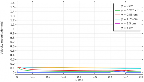
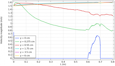
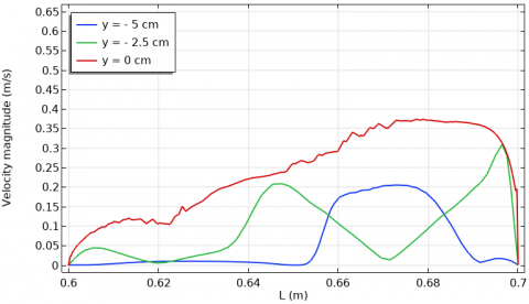
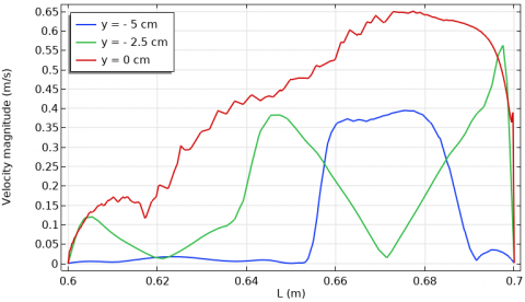
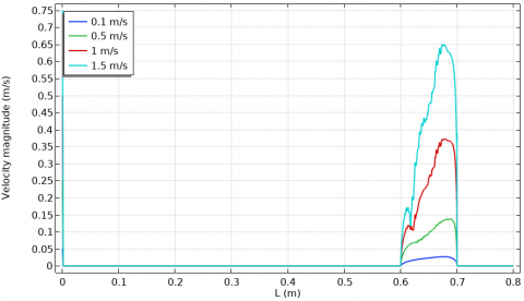
For varied intake air velocities comparable to Reynolds number ranges (2.8814, 14.407, 28.814, and 43.221) and a constant (20 W) power of the source of heat, the distribution of velocity along the positive y-axis in the flow of channel is evinced in Figure 8. And, the greater the space from the lower wall surface, the greater the speed is because the effect of friction on the walls will decrease. For an intake air velocity equivalent to Reynolds number of 2.8814, we notice that the speed is at one level along the channel and begins to rise in the interface between the top enclosure and the duct. And, the channel's laminar velocity profile is influenced via the weakly re-circulating cavity part at the interface zone. Because forced convection is more powerful than the natural convection as well as the shear wall influence, increasing the velocity of air intake raises the velocity profile. This verified very well with study [43].
(a) Vin=0.1 m/s (Re=2.8814)
(b) Vin=0.5 m/s (Re=14.407)
(c) Vin=1 m/s (Re=28.814)
(d) Vin=1.5 m/s (Re=43.221)
Figure 4. Intake air velocity isotherm contour
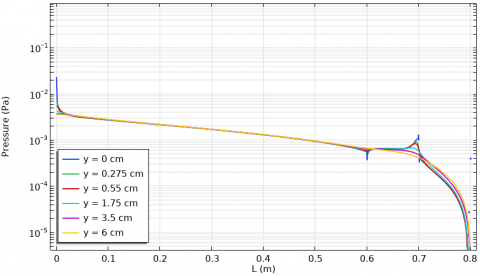
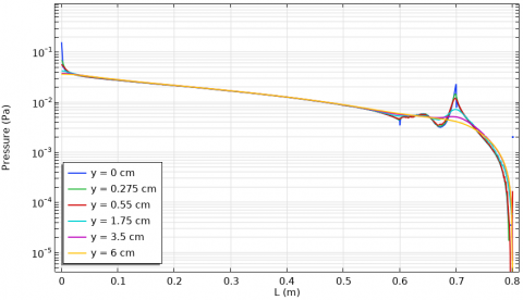
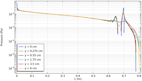
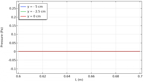
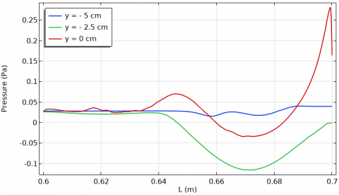
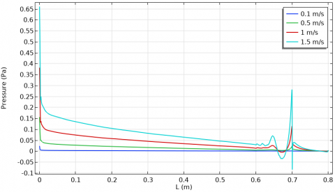
The distribution of pressure through the positive y-axis in the flow of channel at various intake air velocities with a fixed (20 W) power of the source of heat is manifested in Figure 9. It can be seen that pressure is larger at the inlet of the channel and reduces gradually along the channel, and be fluctuating through the interface between the enclosure and channel. Because there's a feeble zone influenced via the incoming pressure from the channel, the distribution of pressure alongside the channel isn't influenced via an increase in the positive y-axis, except for the contact region between the enclosure and channel. If one raises the speed of the air that enters the system, the airflow is going to be more turbulent, leading to a more even distribution of pressure. This verified very well with studies [44, 45].
(a) Vin=0.1 m/s (Re=2.8814)
(b) Vin=0.5 m/s (Re=14.407)
(c) Vin=1 m/s (Re=28.814)
(d) Vin=1.5 m/s (Re=43.221)
Figure 5. Intake air velocity-dependent temperature contours
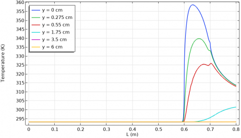
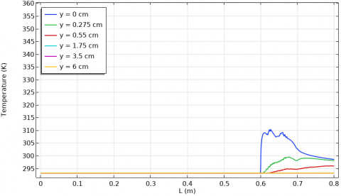
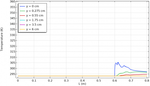
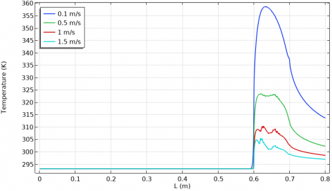
At different intake velocities and a fixed 20 W heat source power, the distribution of temperature alongside the positive y-axis in the assembly of channel-enclosure is revealed in Figure 10. This diagram illustrates how a heat source mounted on the bottom wall of an enclosure causes a temperature gradient along the channel to decrease and the contact region between the enclosure and channel to increase. By increasing the air's velocity at the inlet, one can improve the distribution of temperature inside the enclosure and decrease the heat loss at the interface of channel. And, this is because the natural convection caused via the heated obstacle is going to be amplified by the increased mixing of cold and hot air. This verified very well with studies [46, 47].
By a constant (20 W) power of the source of heat, the distribution of velocity alongside the negative y-axis in the enclosure is shown in Figure 11. If the velocity of air is low, as indicated by a Reynolds number of 2.8814, the distribution of velocities inside the enclosure is almost fixed as well as minimum along the negative y-axis and increases as one approaches the enclosure's end. For the same reason that a higher input air velocity results in a more uniform velocity distribution, a higher absolute y-direction results in a more concentrated flow pattern towards the bottom of the enclosure. This verified very well with study [48].
(a) Vin=0.1 m/s (Re=2.8814)
(b) Vin=0.5 m/s (Re=14.407)
(c) Vin=1 m/s (Re=28.814)
(d) Vin=1.5 m/s (Re=43.221)
Figure 6. Velocity curves at various intake air velocities
The distribution of pressure in the enclosure along the negative y-axis for a range of intake velocities and a fixed 20 W heat source power is elucidated in Figure 7. Through the negative y-axis in the enclosure, the distribution of pressure distribution is almost fixed at low velocities of air corresponding to Reynolds numbers of 2.8814 and 14.407. Due to the recirculation effect, the highest pressure is found near the end of the enclosure, where the intake flow velocity is highest. As y is decreased to negative values, the pressure distribution value stays fixed at the enclosure's top (y= -5 cm) but varies with y-axis declination. This verified very well with study [49].
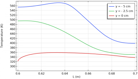
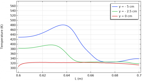
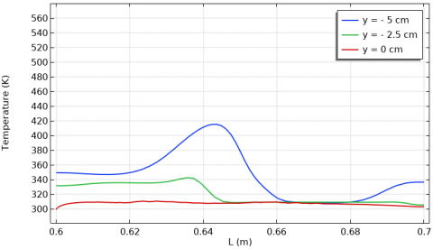
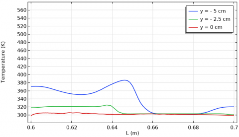
The negative y-axis in Figure 13 portrays the temperature distribution within the enclosure at different intake air velocities while keeping the (20 W) power of the source of heat. If the absolute value of the y-axis goes up, the temperature distribution goes up because the heat source has a greater impact. In other words, the temperature inside the enclosure will drop through the negative y-axis because a higher air intake velocity of the heated source, resulting in more mixing of the cold and hot air. This verified very well with study [50].
(a) Vin=0.1 m/s (Re=2.8814)
(b) Vin=0.5 m/s (Re=14.407)
(c) Vin=1 m/s (Re=28.814)
(d) Vin=1.5 m/s (Re=43.221)
Figure 7. The streamline contours of pressure at various intake air velocities
(a) Vin =0.1 m/s (Re=2.8814)
(b) Vin=0.5 m/s (Re=14.407)
(c) Vin = 1 m/s (Re=28.814)
(d) Vin=1.5 m/s (Re=43.221)
Figure 8. The positive y-axis channel flow velocity distribution at various intake air velocities
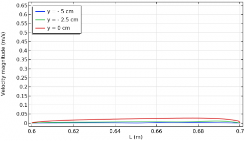
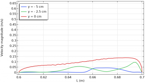
At a fixed (20 W) power of the source of heat, various intake air velocities are shown in Figure 14 to illustrate the local distribution of velocity in the assembly of channel-enclosure. After peaking at the inlet of the channel, the local velocity distribution suddenly dropped (due to the shear stress influence owing to the channel's wall), leveled off in the middle of the channel, and then spiked to its highest value at the end of the enclosure. This verified very well with study [51].
(a) Vin=0.1 m/s (Re=2.8814)
(b) Vin=0.5 m/s (Re=14.407)
(c) Vin=1 m/s (Re=28.814)
(d) Vin=1.5 m/s (Re=43.221)
Figure 9. The positive y-axis channel flow pressure profile at various intake air velocities
At different intake air velocities as well as a fixed (20 W) power of the source of heat, the local distribution of pressure in the system of channel-enclosure is demonstrated in Figure 15. There's a maximal increase and decrease at 0.7 m (midway through the cavity) due to the vigorous re-circulation took place at such point, and the pressure distribution is at its maximum at the inlet of the channel and decreases with distance until the zone of contact between the enclosure and channel, where the distribution will have fluctuated. This verified very well with study [52].
(a) Vin=0.1 m/s (Re=2.8814)
(b) Vin=0.5 m/s (Re=14.407)
(c) Vin=1 m/s (Re=28.814)
(d) Vin=1.5 m/s (Re=43.221)
Figure 10. The positive y-axis channel flow temperature profile at various varying intake air velocities
At different intake air velocities as well as a fixed (20 W) of the source of heat, the local distribution of temperature in the assembly of channel-enclosure is depicted in Figure 16. Since there is no influence of the source of heat, the temperature stays low and stable up to the area of contact between the channel and enclosure, while the temperature dispersion is evident along this zone. And, a rise in the velocity of air intake will cause a lower temperature since more heat will be dissipated from the source. This verified very well with study [53].
(a) Vin=0.1 m/s (Re=2.8814)
(b) Vin=0.5 m/s (Re=14.407)
(c) Vin=1 m/s (Re=28.814)
(d) Vin=1.5 m/s (Re=43.221)
Figure 11. The velocity distribution in enclosure at various intake air velocities during the negative y-axis
(a) Vin=0.1 m/s (Re=2.8814)
(b) Vin=0.5 m/s (Re=14.407)
(c) Vin=1 m/s (Re=28.814)
(d) Vin=1.5 m/s (Re=43.221)
Figure 12. The pressure profile of enclosure through the negative y-axis at various intake air velocities
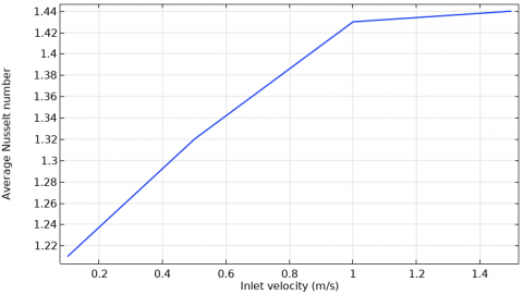
For a constant 20 W heat source power and ε=0.4, as shown in Figure 17, the average Nusselt number varies with air intake velocity. The average Nusselt number rises when inlet air velocity is increased because a higher inlet flow velocity increases heat transmission from the source of heat and, in turn, the heat transfer coefficient. This verified very well with studies [54, 55].
(a) Vin=0.1 m/s (Re=2.8814)
(b) Vin=0.5 m/s (Re=14.407)
(c) Vin=1 m/s (Re=28.814)
(d) Vin=1.5 m/s (Re=43.221)
Figure 13. The temperature of enclosure during the negative y-axis at various intake air velocities
Figure 14. The channel-enclosure's local velocity distribution at varying intake air velocities
Figure 15. The local pressure distribution of the channel-enclosure assembly at various intake air velocities
Figure 16. The temperature distribution of the channel-enclosure assembly at varous intake air velocities
Figure 17. Variation of the average Nusselt number with intake air velocity for ε = 0.4
With the assistance of numerical techniques, the results of this research on the properties of heat transfer due to laminar combined forced convection via a horizontal duct have been achieved. It is determined how much the Reynolds number and the geometrical characteristics of the enclosure have an effect on the transmission of heat. A correlation is developed in order to make a prediction about the efficiency of the heated enclosure's heat transmission. The following are some of the findings that may be drawn from the suggested research:
|
D |
Tube diameter (m) |
|
|
L |
Tube length (m) |
|
|
W |
Cavity width (m) |
|
|
H |
Cavity height (m) |
|
|
r |
Spherical radius of heat source in cavity (m) |
|
|
Tin |
Inlet temperature of flow (K) |
|
|
V |
Flow velocity (m/s) |
|
|
Pw |
Heat power source in cavity (W) |
|
|
Re |
Reynolds number (--) |
|
|
Ri |
Richardson number (--) |
|
|
Pr |
Prandtl number (--) |
|
|
Nu |
Nusselt number (--) |
|
|
g |
Gravitational acceleration (m/s2) |
|
|
P |
Pressure (Pa) |
|
|
Q |
Heat flux (W/m2) |
|
|
Greek symbols |
||
|
$\rho$ |
Density of air (kg/m3) |
|
|
$v$ |
Viscosity (kinematic) of air (m2/s) |
|
|
$\mu$ |
Viscosity (dynamic) of air (kg/m.s) |
|
|
$\varepsilon$ |
Localised heat source Dimensionless length |
|
|
$\theta$ |
Dimensionless temperature |
|
|
$\beta$ |
Coefficient of thermal expansion (1/K) |
|
|
$\alpha$ |
Air thermal diffusivity (m2/s) |
|
|
Subscripts |
||
|
in |
Inlet |
|
|
h |
Hot |
|
|
c |
Cold |
|
|
avg |
Average |
|
[1] Manca, O., Nardini, S., Khanafer, K., Vafai, K. (2003). Effect of heated wall position on mixed convection in a channel with an open cavity. Numerical Heat Transfer: Part A: Applications, 43(3): 259-282. https://doi.org/10.1080/10407780307310
[2] Manca, O., Nardini, S., Vafai, K. (2008). Experimental investigation of opposing mixed convection in a channel with an open cavity below. Experimental Heat Transfer, 21(2): 99-114. https://doi.org/10.1080/08916150701815820
[3] Alam, E.M.M. (2012). Numerical study on conjugate effect of conduction and mixed convection flow in a rectangular ventilated cavity with a heat generating circular block. Post Graduate Thesis of Mathematics (Math), Department of Mathematics, Bangladesh University of Engineering and Technology.
[4] Sekhar, Y.R., Sharma, K., Kamal, S. (2016). Nanofluid heat transfer under mixed convection flow in a tube for solar thermal energy applications. Environmental Science and Pollution Research, 23: 9411-9417. https://doi.org/10.1007/s11356-015-5715-9
[5] Shin, D.H., Kim, C.S., Park, G.C., Cho, H.K. (2017). Experimental analysis on mixed convection in reactor cavity cooling system of HTGR for hydrogen production. International Journal of Hydrogen Energy, 42(34): 22046-22053. https://doi.org/10.1016/j.ijhydene.2017.06.232
[6] Izadi, S., Armaghani, T., Ghasemiasl, R., Chamkha, A.J., Molana, M. (2019). A comprehensive review on mixed convection of nanofluids in various shapes of enclosures. Powder Technology, 343: 880-907. https://doi.org/10.1016/j.powtec.2018.11.006
[7] Kakaç, S., Yüncü, H., Hijikata, K. (1994). Cooling of Electronic Systems. 1 ed.: Springer Netherlands. https://doi.org/10.1007/978-94-011-1090-7
[8] Fu, W.S., Lian, S.H., Lai, Y.C. (2009). A mixed convection in a reciprocating P shape channel with opposite direction of gravity and inlet cooling fluids. Heat Mass Transfer, 45: 679-692. https://doi.org/10.1007/s00231-008-0464-7
[9] Saha, S., Zisan, H.M.T., Tarafdar, U. (2022). Mixed convective flow in a multiple port ventilation square cavity with insulated baffle. Case Studies in Thermal Engineering, 44: 102861. https://doi.org/10.1016/j.csite.2023.102861.
[10] Aylı, E. (2020). Modeling of mixed convection in an enclosure using multiple regression, artificial neural network, and adaptive neuro-fuzzy interface system models. Journal of Mechanical Engineering Science, Proc IMechE Part C, 234(15): 1-16. https://doi.org/10.1177/0954406220914330
[11] Ozgen, F., Varol, Y. (2019). Numerical study of mixed convection in a channel filled with a porous medium. Applied Sciences, 9(2): 211. https://doi.org/10.3390/app9020211
[12] Laouira, H., Oudina, F.M., Hussein, A.K., Kolsi, L., Merah, A., Younis, O. (2019). Heat transfer inside a horizontal channel with an open trapezoidal enclosure subjected to a heat source of different lengths. Heat Transfer—Asian Research, 49(1): 406-423. https://doi.org/10.1002/htj.21618
[13] Bahlaoui, A., Raji, A., Lamsaadi, M., Mi, M.N., Hasnaoui, M. (2007). Mixed convection in a horizontal channel with emissive walls and partially heated from below. Numerical Heat Transfer, Part A, 51(9): 855-875. https://doi.org/10.1080/10407780601112746
[14] Doghmi, H., Abourida, B., Belarche, L., Sannad, M., Ouzaouit, M. (2017). Mixed convection in a three-dimensional ventilated cavity with two isothermal heating Sections. E3S Web of Conferences, 22: 00036. https://doi.org/10.1051/e3sconf/20172200036
[15] Rahman, M.M., Parvin, S., Rahim, N.A., Hasanuzzaman, M., Saidur, R. (2012). Simulation of mixed convection heat transfer in a horizontal channel with an open cavity containing a heated hollow cylinder. Heat Transfer-Asian Research, 41(4): 339-353. https://doi.org/10.1002/htj.21002
[16] Eleiwi, M.A., Tahseen, T.A., Ghareeb, A.H. (2020). Intelligent control based estimation of heat transfer coefficient from four flat tubes with different attack air angles. J. Adv. Res. Fluid Mech. Therm. Sci.,72(72): 65-78. https://doi.org/10.37934/ARFMTS.72.2.6578
[17] Ahmed, S.Y., Jabbar, M.Y., Hamzah, H.K., Ali, F.H., Hussein, A.K. (2020). Mixed convection of nanofluid in a square enclosure with a hot bottom wall and a conductive half‐immersed rotating circular cylinder. Heat Transfer, 49(8): 4173-4203. https://doi.org/10.1002/htj.21822
[18] Abdulkarim, A.H., Eleiwi, M.A., Tahseen, T.A., Canli, E. (2021). Numerical forced convection heat transfer of nanofluids over back facing step and through heated circular grooves. Math. Model. Eng. Probl., 8(4): 597-610. https://doi.org/10.18280/mmep.080413
[19] Rahmati, A.R., Roknabadi, A.R., Abbaszadeh, M. (2016). Numerical simulation of mixed convection heat transfer of nanofluid in a double lid-driven cavity using lattice Boltzmann method. Alexandria Engineering Journal, 55(4): 3101-3114. https://doi.org/10.1016/j.aej.2016.08.017
[20] Rana, P., Bhargava, R. (2011). Numerical study of heat transfer enhancement in mixed convection flow along a vertical plate with heat source/sink utilising nanofluids. Communications in Nonlinear Science and Numerical Simulation, 16(11): 4318-4334. https://doi.org/10.1016/j.cnsns.2011.03.014
[21] Eleiwi, M.A., Zainal, O.A., Tahseen, T.A., Mustafa, A.W. (2021). Effect of front air attack angles on heat transfer coefficient of the cross-flow of four flat tube. Heat Transf., 50(1): 638-654. https://doi.org/10.1002/htj.21897
[22] Bahlaoui, A., Raji, A., Hasnaoui, M., Naïmi, M., Makayssi, T., Lamsaadi, M. (2009). Mixed convection cooling combined with surface radiation in a partitioned rectangular cavity. Energy Conversion and Management, 50(3): 626-635. https://doi.org/10.1016/j.enconman.2008.10.001
[23] Eleiwi, M.A., Tahseen, T.A., Hameed, A.F. (2020). Numerical study of fluid flow and heat transfer in a backward facing step with three adiabatic circular cylinder. J. Adv. Res. Fluid Mech. Therm. Sci., 72(1): 80-93. https://doi.org/10.37934/arfmts.72.1.8093
[24] Sabbar, W.A., Ismael, M.A., Almudhaffar, M. (2018). Fluid-structure interaction of mixed convection in a cavity-channel assembly of flexible wall. International Journal of Mechanical Sciences, 149: 73-83. https://doi.org/10.1016/j.ijmecsci.2018.09.041
[25] Gangawane, K.M., Gupta, S. (2018). Mixed convection characteristics in rectangular enclosure containing heated elliptical block: Effect of direction of moving wall. International Journal of Thermal Sciences, 130: 100-115. https://doi.org/10.1016/j.ijthermalsci.2018.04.010
[26] Rajamohan, G., Ramesh, N., Kumar, P. (2019). Mixed convection and radiation studies on thermally developing laminar flow in a horizontal square channel with variable side heated wall. International Journal of Thermal Sciences, 140: 298-307. https://doi.org/10.1016/j.ijthermalsci.2019.03.002
[27] Bahlaoui, A., Raji, A., Hasnaoui, M., Ouardi, C., Naïmi, M., Makayssi, T. (2011). Height partition effect on combined mixed convection and surface radiation in a vented rectangular cavity. Journal of Applied Fluid Mechanics, 4(1): 89-96.
[28] Mebarek-Oudina, F., Laouira, H., Aissa, A., Hussein, A.K., El Ganaoui, M. (2020). Ganaoui, convection heat transfer analysis in a channel with an open trapezoidal cavity: Heat source locations effect. MATEC Web of Conferences, 330: 01006. https://doi.org/10.1051/matecconf/202033001006
[29] Sivasankaran, S., Janagi, K. (2022). Numerical study on mixed convection flow and energy transfer in an inclined channel cavity: Effect of baffle size. Mathematical and Computational Applications, 27(1): 9. https://doi.org/10.3390/mca27010009
[30] Bahlaoui, A., Raji, A., Hasnaoui, M., El Ayachi, R., Naimi, M., Makayssi, T., Lamsaadi, M. (2008). Numerical study of mixed convection copled with radiation in a vented partitioned enclosure. Альтернативная энергетика и экология, (6): 131-137.
[31] Rahul, K.C. (2017). Numerical simulations of mixed convection from a horizontal channel with radiating heat sources. International Journal of Engineering Research & Technology, 6(1): 49-57.
[32] Esfe, M.H., Arani, A.A., Niroumand, A.H., Yan, W.M., Karimipour, A. (2015). Mixed convection heat transfer from surface-mounted block heat sources in a horizontal channel with nanofluids. International Journal of Heat and Mass Transfer, 89: 783-791. https://doi.org/10.1016/j.ijheatmasstransfer.2015.05.100
[33] Hussein, A.K., Hamzah, H.K., Ali, F.H., Kolsi, L. (2020). Mixed convection in a trapezoidal enclosure filled with two layers of nanofuid and porous media with a rotating circular cylinder and a sinusoidal bottom wall. Journal of Thermal Analysis and Calorimetry, 141: 2061-2079. https://doi.org/10.1007/s10973-019-08963-6
[34] Abd Al-Hassan, A.Q., Ismael, M.A. (2019). Numerical study of double diffusive mixed convection in horizontal channel with composite open porous cavity. Special Topics & Reviews in Porous Media-An International Journal, 10(4): 401-419. https://doi.org/10.1615/SpecialTopicsRevPorousMedia.2019029342
[35] Laouira, H., Oudina, F.M., Hussein, A.K., Kolsi, L., Merah, A., Younis, O. (2019). Heat transfer inside a horizontal channel with an open trapezoidal enclosure subjected to a heat source of different lengths. Heat Transfer—Asian Research, 49(1): 406-423. https://doi.org/10.1002/htj.21618
[36] Rashid, F.L., Khalaf, A.F., Hussein, A.K., Hamida, M.B., Ali, B., Younis, O. (2022). Thermal-hydraulic analysis of transient conjugate heating between hemi-spherical body and air. Frontiers in Heat and Mass Transfer (FHMT), 19(21). http://dx.doi.org/10.5098/hmt.19.21
[37] Rashid, F.L., Fakhrulddin, S.K., Eleiwi, M.A., Hussein, A.K., Tahseen, T.A., Younis, O., Ahmed, M.I. (2022). CFD simulation in thermal-hydraulic analysis of air flow on different attack angles of row flat tube. Frontiers in Heat and Mass Transfer (FHMT), 19(6). https://doi.org/10.5098/hmt.19.6
[38] Rashid, F.L., Hussein, A.K., Malekshah, E.H., Abderrahmane, A., Guedri, K., Younis, O. (2022). Review of heat transfer analysis in different cavity geometries with and without nanofluids. Nanomaterials, 12(14): 2481. https://doi.org/10.3390/nano12142481
[39] Eleiwi, M.A., Rashid, F.L., Khalaf, A.F., Tuama, S.A. (2022). Numerical investigation of conjugate heat transfer between spherical solid body and fluid. Mathematical Modelling of Engineering Problems, 9(2): 491-497. https://doi.org/10.18280/mmep.090227
[40] Altaie, A., Hasan, M.R., Rashid, F.L. (2014). Numerical heat transfer and turbulent flow in a circular tube fitted with opened rings having square cross section. Journal of Basic and Applied Scientific Research, 4(11): 28-36.
[41] Rashid, F.L., Altaie, A., Hasan, M. R. (2014). Numerical investigation of heat transfer enhancement in a circular tube using ribs of separated ports assembly. European Scientific Journal, 2: 172-183.
[42] Altaie, A., Hasan, M.R., Rashid, F.L. (2015). Numerical investigation of heat transfer enhancement in a circular tube with rectangular opened rings. Bulletin of Electrical Engineering and Informatics, 4(1): 18-25. https://doi.org/10.11591/eei.v4i1.331
[43] Altaie, A., Hasan, M.R., Rashid, F.L. (2015). Heat transfer enhancement in a circular tube using ribs with middle arm. Elixir International Journal.
[44] Altaie, A., Hasan, M.R., Rashid, F.L. (2015). Numerical investigation in a circular tube to enhance turbulent heat transfer using opened rings-triangular cross section. Journal of Babylon University/ Engineering Sciences, 23(3).
[45] Rashid, F.L., Al-Jibory, M.W., Hussein, H.Q. (2017). Cooling enhancement in gas turbine blade using coated circular ribs with a new nanocomposite material. Patent (5092).
[46] Al-Jibory, M.W., Rashid, F.L., Hussein, H.Q. (2018). Heat transfer augmentation in gas turbine blade rectangular passages using circular ribs with fins. Journal of University of Babylon, Engineering Sciences, 26(1): 247-258.
[47] Al-Jibory, M.W., Rashid, F.L., Talib, Sh.M. (2018). Numerical investigation of heat transfer enhancement in ribbed elliptical passage. Journal of Engineering and Applied Sciences, 13(17): 7223-7234.
[48] Rashid, F.L., Azziz, H.N., Hussein, E.Q. (2018). Heat transfer enhancement in air cooled gas turbine blade using corrugated passages. Journal of Petroleum Research & Studies, 20: 52-69.
[49] Azziz, H.N., Shareef, A.S., Rashid, F.L. (2018). Experimental investigation of the heat transfer for the effect of nanoparticles with different base fluid and solar collector tilt angle. Journal of Engineering and Applied Sciences, 13(13): 10614-10620.
[50] Aljibory, M.W., Rashid, F.L., Alais, S.M. (2018). An Experimental and numerical investigation of heat transfer enhancement using annular ribs in a tube. IOP Conference Series: Materials Science and Engineering, 433(1): 012057. https://doi.org/10.1088/1757-899X/433/1/012057
[51] Rashid, F.L., Al-Jibory, M.W., Talib, Sh.M. (2018). Numerical investigation of heat transfer augmentation in elliptical passage with different rib geometries and aspect ratios. International Journal of Mechanical Engineering and Technology, 9(13): 1390-1409.
[52] Al-Jibory, M.W., Rashid, F.L., Talib, Sh.M. (2018). An experimental investigation of heat transfer enhancement in elliptical passage fitted with different rib geometries. International Journal of Mechanical Engineering and Technology, 9(13): 1033-1048.
[53] AL-Jibory, M.W., Rashid, F.L., Talib, Sh. M. (2020). Review on cooling enhancement of different shape gas turbine ribbed blade with thermal barrier coating. International Journal of Scientific Research and Engineering Development, 3(1): 313-329.
[54] AL-Jibory, M.W., Rashid, F.L., Hussein, H.Q. (2020). Review of heat transfer enhancement in air-cooled turbine blades. International Journal of Scientific & Technology Research, 9(4): 3123-3130.
[55] Hussein, H.Q., Al-Jibory, M.W., Rashid, F.L. (2020). Heat transfer enhancement of gas turbine blades using coated ribs with nanocomposite materials. Journal of Mechanical Engineering Research and Developments, 43(6): 9-22.