Yonggao Cheng | Yanqing Wu* | Siran Bai
© 2021 IIETA. This article is published by IIETA and is licensed under the CC BY 4.0 license (http://creativecommons.org/licenses/by/4.0/).
OPEN ACCESS
Compared with the traditional hot water production methods, heat pump systems have the unique advantages of high efficiency, energy saving, and eco-friendly, so they have a very good promotion and application prospect. The sewage source heat pump systems can recover the waste heat of high-temperature sewage produced in residential communities, for this reason, this study integrated the proven air source heat pump technology with the sewage source heat pump technology and conducted a research on the smart community waste heat recovery system based on the air-source/sewage-source Compound Heat Pump system (CHP system). In the paper, the design steps and equipment selection flow of the proposed system were given, the waste heat utilization rate of the proposed system was calculated, and the obtained experimental results verified the energy-saving effect of the proposed system, which had provided a reference for the application of the compound heat pumps in other occasions.
air source heat pump, sewage source heat pump, waste heat recovery
As Chinese people’s living standards are improving constantly, the consumption of domestic hot water by residents is increasing as well. Compared with developed countries, China's per capita consumption of hot water is still at a lower level. According to statistics, the existing domestic hot water production methods mainly include coal-fired, gas-fired, and oil-fired boilers, solar heating systems, electric heating systems, and air source heat pump systems [1-4], etc. The water heating mechanism of boiler systems is to burn fossil fuels and convert the combustion heat into the heat energy of hot water; while the mechanism of electric systems is to consume electricity and convert electricity, solar energy, and other heat sources into the heat energy of hot water [5-8]. Compared with other hot water production methods, heat pump systems have the advantages of high efficiency, energy saving, eco-friendly, so they have a very good promotion and application prospect.
If the fossil fuel of the heating furnace is not fully burned, it will cause problems such as low heating efficiency and large harmful gas emissions [9, 10]. Dehghan [11] constructed a mathematical model for the different circulation modes of the high-temperature sewage source heat pump systems which can replace the traditional heating furnace systems; through an analysis of the thermal performance of the entransy dissipation system in the heat exchange processes on the load side and the source side, the study proposed a reasonable value for the temperature drop of the sewage on the load side and the source side. Meng et al. [12] simulated the operation of high-temperature sewage source heat pump systems under different load conditions, and verified that the heat pump systems with frequency conversion function are energy-saving, economical, and eco-friendly. With the increase in fossil fuel consumption, environmental problems such as urban heat islands, global warming, ozone layer destruction, and heavy smog in big cities have become increasingly prominent. In recent years, the Chinese government has introduced a series of energy-saving and emission-reduction technologies such as the low-temperature waste heat power generation [13-15]. Scholars Deymi-Dashtebayaz and Valipour-Namanlo [16] measured and analyzed the residual heat of the circulating cooling water of the steam turbine and the boiler slag cooler that are used in circulating cooling water waste heat recovery system of the thermal power plants, and selected the model of the heat pump unit based on the measurement and calculation results. Combining with the actual situations of a power plant, Li et al. [17] proposed two solutions for the recovery of circulating water waste heat, one is the compression-type heat pump unit, and the other is the absorption-type heat pump unit; based on a summarization of the operating data of heating seasons and the heat recovery data of the machine set, they gave a comparative analysis on the economics of the two solutions. Aiming at the large amount of waste heat resources carried by the bathing sewage that can be recycled, Cao et al. [18] conducted application research and measurement analysis on the waste heat recovery of bathing sewage from colleges and universities based on the heat pump technology, then they sorted out the existing problems, and analyzed the performance of three designed systems in terms of economics, environmental protection evaluation, and thermodynamic efficiency; after that, they determined that an indirect sewage source heat pump + thermal storage electric hot water boiler method with higher efficiency was the optimal solution. Since there’re differences in the techniques and operation performance of compression-type heat pumps and absorption-type heat pumps, some scholars have carried out relevant studies, for example, Zhang et al. [19] analyzed the influence of different external water temperature conditions on the supply water temperature of the water source side and the user side of the heat pump unit and the temperature of the driving heat source; then, combining with the actual operating conditions of the two types of machine sets of the compression-type and absorption-type heat pumps, they measured and calculated the waste heat recovery rate and evaluated the system’s performance in energy conservation and energy utilization. Singh et al. [20] evaluated the compression-type and absorption-type heat pumps from an economic point of view, constructed an evaluation model to assess their energy-saving benefits and economic benefits, and used two real cases to measure and calculate the static payback time and the net present value of the system at different stages. Han et al. [21] introduced the technology of thermal power plant condensing waste heat recovery into an absorption-type heat pump system that has two heating cycles of high-temperature heating cycle and the low-temperature heating cycle, they constructed a system thermal calculation model and proposed the heat-electricity co-generation conditions under different working conditions; then, their study extracted the features of the properties of heat pumps under corresponding conditions, and gave a customized composite heat pump unit design scheme based on the system coordination degree and completion indicators.
With the change of energy consumption structure, heat pump technology will have a greater development space. In terms of function and technology, the air source heat pump technology that is being promoted at this stage is quite mature already, while the application of sewage source heat pump technology is much less. In order to effectively improve the efficiency and reliability of the heat pump systems, this paper integrated the air source heat pump technology with the sewage source heat pump technology to study the smart community waste heat recovery system based on compound heat pump. In the first part, this paper reviewed and summarized the existing research results, and introduced the structure of this manuscript; the second part designed the CHP-based smart community waste heat recovery system; the third part calculated the waste heat utilization rate of the proposed system; the fourth part used experimental results to verify the energy-saving effect of the CHP system; the fifth part drew the conclusions.
Heat pumps are a kind of energy-enhancing device that consumes higher heating value energies and converts excess heat or industrial waste heat contained in air and water into the heat energy that can be used directly. Compared with other heating methods, heat pumps save more higher heating value energies during the working process, and reduce the exhaust gas emission produced by burning fossil fuel. For compression-type heat pumps, during the operation process, the 4 parts of evaporator, compressor, condenser, and throttling device inside the pump form a thermodynamic cycle by continuously converting the working medium of the heat pump from the evaporation state to the compression state, and then to the condensation state and the throttling state, and finally returning to the evaporation state. When an equipment is in operation, the compressor drives the refrigerant to absorb heat from the surrounding environment, suppose HE represents the absorbed heat, H represents the heat transferred through the thermodynamic cycle process, D represents the driving work of the compressor input externally during the cycle, then, according to the first law of thermodynamics, there is:
$H=H_{E}+D$ (1)
There are many types of heat pumps. The air source heat pumps transfer the heat drawn from the surrounding air to the hot water through the thermodynamic cycle process; they have been widely used due to their merits of safe, energy-saving, and water-electricity separation. The sewage source heat pumps absorb excess heat from the high temperature sewage to heat the cold water. According to the type of sewage source, the sewage source heat pumps are divided into two types: the raw sewage heat pumps, and the secondary treatment sewage heat pumps. Sewage source heat pumps have the advantages of small water temperature fluctuations, stable and reliable operation, and irrespective of frosting.
Figure 1. Structure of the CHP system
When the circulating heat pump is replenishing water, the adverse effects of shortened compressor service life and poor user experience can be easily caused by the decrease of water temperature in the hot water tank. In order to solve these problems and fully recover the heat of bathing sewage, this study designed a compound heat pump (CHP) system that integrated air source heat pump units and sewage source heat pump units. Figure 1 gives the structure of the CHP system. The core components of the CHP system are air source heat pump units and sewage source heat pump units, and the auxiliary components include: circulating heating water tanks, various circulating pumps, preheating heat exchangers, hot water storage tanks, sewage collection equipment, and cleaning and filtering devices, etc. To realize energy conservation and efficient operation of the CHP system, the system operation modes could be adjusted by operating the valves according to the ambient temperature and the water level of the water tank to realize hot water circulation, sewage circulation, and cleaning cycle of the sewage circuit of the system.
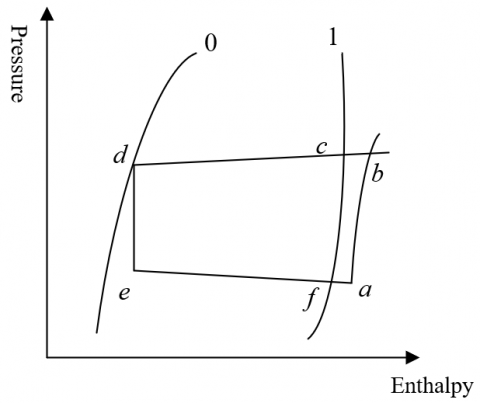
Figure 2. Pressure-enthalpy curve of the thermodynamic cycle of CHP system
Figure 2 shows the pressure-enthalpy curves of the thermodynamic cycle of the CHP system in actual situations. In Figure 2, 1 and 0 are the pressure-enthalpy curves of the actual circulations of the heat pump water heater. The evaporation process in the evaporator is from point e to point f. Due to the pressure drop of the refrigerant caused by the flow resistance in the evaporator and the heat transfer temperature difference between the refrigerant and the cooled working medium of the heat pump, this process is described as a straight line inclined to the lower right. The two processes of isobaric overheating and isenthalpic throttling of the refrigerant from the outlet of the evaporator to the inlet of the compressor are from point f to point a, which is described by the change of the pressure and temperature of the refrigerant. The figure also shows the process of pressure drop and temperature drop of the condenser from point b to point c, and the process of the cooling and condensation of the refrigerant from point c to point d. Similarly, during the process from point c to point d, due to the pressure drop of the refrigerant caused by the flow resistance in the evaporator and the heat transfer temperature difference between the refrigerant and the cooled working medium of the heat pump, the pressure gradually decreases and the condensation temperature changes constantly. The process from point d to point e is the throttling stage including the heat exchange process between the refrigerant and the environment, and the enthalpy value is almost the same before and after the process.
According to above analysis, it is difficult to manually calculate the thermodynamic cycle shown in Figure 2, so it’s necessary to simplify the cycle process. A few assumptions were made to set the ideal thermodynamic cycle for the heat pump system, such as the compressor working process was an isentropic compression process; the refrigerant heat transfer temperature difference, the flow resistance loss, and the leakage heat loss were ignored; and the throttling process was isenthalpic throttling, etc. Then, based on these assumptions, the pressure-enthalpy relationship curves in Figure 2 can be directly used to calculate the performance indicators of the thermodynamic cycle of the system.
2.1 Design of the air source heat pump system
The unit condensation heat cu generated during the pressure drop and temperature drop process experienced by the condenser of the air source heat pump can be calculated by Formula 2:
$c_{1}=e_{b}-e_{a}$ (2)
Suppose ξI represents the indicated efficiency of the compressor, after the pressure drop and temperature drop process of the condenser shown in Formula 2, the enthalpy value can be calculated by Formula 3:
$e_{b}=\frac{e_{b}^{\prime}-e_{a}}{\xi_{I}}+e_{a}$ (3)
The unit work consumed in this process can be expressed as:
$D_{u}=e_{b}^{\prime}-e_{a}$ (4)
Suppose σ represents the constant-pressure specific heat capacity of water, Nday represents the daily water consumption, τ1 and τ2 respectively represent the water supply temperature and tap water temperature, Ψ represents the safety factor, and tr represents the daily operating time of the heat pump unit, then the unit heat production HT of the air source heat pump system can be calculated by Formula 5:
$H_{T}=\frac{\sigma \times N_{d q v} \times\left(\tau_{1}-\tau_{2}\right) \times \Psi}{t_{r} \times 60^{2}}$ (5)
The circulation flow of refrigerant c2 can be calculated by Formula 6:
$c_{2}=\frac{H_{T}}{c_{1}}$ (6)
Suppose μ1, μ2, μ3, and μ4 respectively represent the volume coefficient, pressure coefficient, temperature coefficient, and leakage coefficient of the water heater compressor of the air source heat pump, then the air delivery coefficient of the compressor can be calculated by Formula 7:
$\mu=\mu_{1} \times \mu_{2} \times \mu_{3} \times \mu_{4}$ (7)
The actual air delivery volume of the compressor can be expressed by Formula 8:
$Q_{A}=c_{2} \times q_{1}$ (8)
The theoretical air delivery volume of the compressor is:
$Q_{T}=\frac{Q_{A}}{\mu}$ (9)
The theoretical power of the compressor can be calculated by Formula 10:
$G_{T}=c_{2} \times D_{u}$ (10)
The corresponding indicated power can be expressed as:
$G_{I}=\frac{G_{T}}{\xi_{I}}$ (11)
Suppose ξ2 represents the mechanical efficiency, Formula 12 gives the formula for calculating the shaft power of the compressor:
$G_{S}=\frac{G_{I}}{\xi_{2}}$ (12)
Suppose ξM represents the motor efficiency of the heat pump system, then the power efficiency of the system is ξE=ξj×ξ×ξM, and the input power of the compressor motor can be calculated by the following formula:
$G_{E}=\frac{G_{T}}{\xi_{E}}$ (13)
The overall heating coefficient of the heat pump system can be calculated by Formula 14:
$H H C_{A}=\frac{H_{T}}{G_{S}}$ (14)
Based on above thermal calculation results of the air source heat pump, the appropriate water heater model can be selected.
2.2 Design of the sewage source heat pump system
Suppose HL and FR respectively represent the waste heat recovery load and flow of the higher temperature community bathing sewage, λSC and ρ respectively represent the sewage collection coefficient and density, ts represents the operating time of the sewage source heat pump, then the total waste heat recovery volume of the sewage source heat pump can be calculated by Formula 15:
$H_{L}=\lambda_{S C} \times \rho \times \sigma \times F_{R} \times \frac{\Delta t}{t_{s} \times 60^{2}}$ (15)
By reorganizing and iterating formulas 10-13, the calculation formula of the heating coefficient of the sewage source heat pump system can be obtained:
$H H C_{S}=\frac{c_{1}}{D_{u}} \times \xi_{I} \times \xi_{S}$ (16)
For the sewage source heat pump unit, within the 24 operating hours in a single day, suppose H1 and D1 respectively represent the heat supply of the heat pump unit and the power consumption for heating per volume tap water, then there is:
$H H C_{S}=\frac{H_{1}}{D_{1}}=\frac{H_{L}+D_{1}}{D_{1}}$ (17)
The circulating flow of the refrigerant can be calculated by Formula 18:
$c_{2}=\frac{H_{1}}{c_{1}}$ (18)
At this time, the calculation formulas of GT, GI, and GS of the system compressor can be expressed as:
$\left\{\begin{array}{c}G_{0}=c_{2} \times D_{u} \\ G_{I}=\frac{G_{T}}{\xi_{I}} \\ G_{S}=\frac{G_{I}}{\xi_{S}}\end{array}\right.$ (19)
Based on above calculation results of the sewage source heat pump, the appropriate machine set model can be selected; meanwhile, the selected sewage source heat pump and air source heat pump were integrated to constitute the CHP system.
2.3 Selection of related components
To enable the hot water supply of the CHP system to meet the peak hot water demand of the community, it is necessary to set sufficient volume for the hot water storage tanks and circulating heating water tanks of the CHP system. Suppose HP and HT respectively represent heat consumption and heat supply of the water tank in per unit time, t represents the duration of the heat consumption of the water tank in per unit time, δ represents the effective heat storage volume coefficient of the water tank, then the volume of the water tank ω can be calculated by Formula 20:
$\omega=\psi^{\prime} \times \frac{\left(H_{P}-H_{T}\right) \times \tau_{4}}{\delta \times\left(t_{P}-t_{T}\right) \times \sigma \times s_{P}}$ (20)
In the CHP system proposed in this study, a circulating pump was added between the air source heat pump unit, the sewage source heat pump unit, and the circulating heating water tank each, and a booster pump was added between the hot water storage tank and the water supply valve. Whether the community sewage source supply pipeline leads to the circulating heating water tank or to the preheating heat exchanger was controlled by the shut-off valve. Suppose MF represents the equivalent volume of sewage in the supply pipeline, β is a preset undetermined coefficient, then, the unit flow of sewage in the supply pipeline cS, which characterizes the boosting performance indicator of the booster pump, can be calculated by Formula 21:
$c_{S}=0.2 \beta \sqrt{M_{F}}$ (21)
2.4 Design of the control system
Suppose υ1 and υ2 respectively represent the temperature of the sewage in the sewage tank and the temperature at the tap water inlet measured by the temperature sensor, ∆υ represents the preset temperature difference, then the preset temperature difference ∆υ which characterizes the operation control effect of the CHP system can be expressed as:
$\Delta v=v_{1}-v_{2}$ (22)
Suppose LC-max and LC-min are the highest and lowest liquid levels of the circulating heating water tank, the water replenishment control mode of the CHP system can be set as: when the liquid level drops to LC-min, water is replenished to the water tank under the temperature difference control mode. When ∆υ is less than υ, valves 1 and 3 are opened, valves 2, 4, and 5 are closed, the tap water supply of the community directly enters the circulating heating water tank; when ∆υ is greater than υ, valves 1, 3, and 5 are closed, valves 2, 4 are opened, the preheating heat exchanger preheats the tap water and then feeds it into the circulating heating water tank.
In this study, the liquid level control of the water tank and the control mode of prioritizing the sewage source heat pump unit were combined to realize the effective circulating heating of hot water of the CHP system. Suppose LH-max and LH-min represent the highest and lowest liquid levels of the hot water storage tank, LH and p represent the corresponding liquid levels in the hot water storage tank; when the liquid level drops to LH-min, the circulating heating water tank replenishes hot water in a timely manner, at the same time, based on the real-time monitoring data of LH and p fed back by the sensor, controls such as increasing or decreasing loads of the total output energy of the system would be performed automatically. In the proposed system, the default loading sequence is that the sewage source heat pump units have priority over the air source heat pump units; and the default unloading sequence is the air source heat pump units come first, and the sewage source heat pump units come later.
In this paper, the waste heat utilization rate was used to describe the degree of recovery and utilization of the waste heat resources of the CHP system, that is, the proportion of the recovered waste heat in the waste heat resources was calculated. Suppose HRY-I and HRY-O represent the values of heat contained in the sewage source of the community when it enters and leaves the CHP system; HRY-max represents the maximum heat discharge of the sewage, namely the value of heat contained by the sewage when it just flows into the drainage channel, and HRY-min represents the minimum heat discharge of the sewage, then the waste heat utilization rate can be defined as:
$\varphi=\frac{H_{R Y-I}\quad-H_{R Y-O}}{H_{R Y-\max }\quad-H_{R Y-\min }}$ (23)
Suppose τRY-I and τRY-O respectively represent the temperature values of community sewage when it enters and leaves the CHP system, τRY-O represents the maximum discharge temperature of the sewage, which is the real-time temperature when the sewage just flows into the drainage channel, and τRY,min represents the minimum discharge temperature of sewage. Neglecting the loss of sewage during operation, then the waste heat utilization rate in Formula 23 can be simply estimated by the temperature values measured by the temperature sensor:
$\varphi=\frac{\tau_{R Y-I}\quad-\tau_{R Y-O}}{\tau_{R Y-\max }\quad-\tau_{R Y-\min }}$ (24)
After analyzing the history data of the temperature of community bathing sewage and public bathroom sewage, the highest temperature value τRY,max of community sewage when it just enters the drainage channel was within the range of [38.4, 42.1], while for the temperature values of community sewage when enters and leaves the CHP system τRY-I and τRY-O, their respective value ranges were [29.3, 35.8] and [8.5, 14.2]; in practice, the limit value of the minimum discharge temperature of the community sewage τRY,min is generally set to 5.5°C. Based on above empirical value and the actually measured value, the proportion of community sewage heat utilization in the heated water volume at present could be calculated:
$\eta=\frac{\tau_{O}-\tau_{R}}{\tau_{O}-\tau_{S}} \times 100 \%$ (25)
During experimental platform construction, the investment cost and annual operation cost of the CHP system were estimated. The system investment cost included the equipment purchase cost, installation cost, and environment renovation cost, etc.; and the annual operation cost included water charge, fuel cost, sewage discharge fee, depreciation expense, maintenance cost, and staff salary, etc. To facilitate comparison, this paper mainly considered the equipment purchase cost, fuel cost, managerial staff salary, equipment depreciation expense, and equipment maintenance cost. During calculation, the equipment maintenance fee was calculated as 2.5% of the equipment investment cost, and the equipment depreciation expense was calculated as equipment purchase cost × (1-4%)/equipment service life. Table 1 gives the calculation results of the investment and operation costs of the CHP system.
Table 2 shows the pressure, time, and enthalpy of the thermodynamic cycle of the CHP system. The left columns are the status of the air source heat pump units, and the right columns are the status of the sewage source heat pump units. Based on the data in Table 1 and the pressure-enthalpy curve in Figure 2, the calculation of the performance indicators of thermodynamic cycle of the system could be realized.
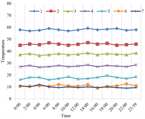
In order to obtain more accurate temperature values of the bathing sewage, for the sewage flowing through the preheating heat exchanger and the evaporator of the sewage source heat pump units on a certain day, the following temperature values were measured: the water temperature of the hot water storage tank 1, the water temperature of the circulating heating water tank, the sewage temperature 3, the temperature of sewage after preheating 4, sewage drainage temperature 5, tap water temperature 6, outdoor ambient temperature 7. According to Figure 3, the outdoor ambient temperature and the tap water temperature were relatively stable, and their average values were 10.1°C and 13.2°C respectively. The temperature range of the hot water storage tank was approximately [57, 59]. The small fluctuations of water temperature in the above four aspects proved that the operation of the air source heat pump units in the CHP system was stable. The average temperature of the sewage in the community was 37.1℃. In the process of waste heat recovery, the average temperature of the preheated sewage at the outlet of the preheating heat exchanger was 27.5°C, and the average temperature of the sewage discharge at the outlet of the sewage source heat pump units was 16.1°C, through calculation, it’s obtained that the energy recovered from the waste heat of sewage accounted for more than 1/3 of the total energy of hot water stored in the water tank, which had verified that the proposed CHP system had a good energy-saving effect.
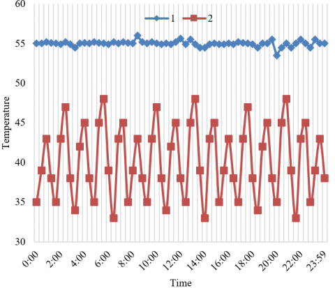
Next, the change law of energy consumption with water temperature within the thermodynamic cycle of the CHP system was analyzed. Thermocouples were used to measure the water temperature at different depths of the circulating heating water tank. Figure 4 shows the change of water temperature, which describes the law of water heating of the system. According to the figure, the hot water temperature of the hot water storage tank was basically stable within the range of 55±3℃, which had verified that the CHP system can still respond to various internal and external disturbances during the peak hours of hot water supply in the community, and the operation was stable and reliable. The water temperature in the circulating heating water tank showed periodical changes, within 24hours on a single day, there’re a total of 16 equal-amplitude oscillation periods, the fluctuation range of the water temperature was [34, 48], and a total of 210m3 qualified hot water had been produced.
Table 1. Investment and operation costs of the CHP system
|
|
Cost type |
Equipment/Model |
Number |
Unit price |
Total |
|
Investment cost |
Main equipment |
Air source heat pump unit |
5 |
7.5 |
37.5 |
|
Sewage source heat pump unit |
6 |
2.6 |
15.6 |
||
|
Auxiliary equipment |
Hot water storage tank |
3 |
1.2 |
3.6 |
|
|
Circulating heating water tank |
2 |
0.4 |
0.8 |
||
|
Circulating pump |
4 |
0.5 |
2.0 |
||
|
Operation cost |
Fuel cost |
14.26 |
14.26 |
||
|
Maintenance cost |
1.2 |
1.2 |
|||
|
Depreciation expense |
3.5 |
3.5 |
|||
|
Sewage discharge fee |
0.8 |
0.8 |
|||
|
Staff salary |
2.4 |
2.4 |
|||
Table 2. Pressure-enthalpy of the thermodynamic cycle of CHP system
|
Air source heat pump units |
Sewage source heat pump units |
||||
|
Status point |
Parameter |
Value |
Status point |
Parameter |
Value |
|
f |
p1 |
412.6 |
f' |
p1 |
675.7 |
|
t1 |
-4.9 |
t1 |
9 |
||
|
e1 |
401.35 |
e1 |
407.32 |
||
|
a |
p2 |
418.27 |
a' |
p2 |
675.7 |
|
t2 |
0 |
t2 |
12 |
||
|
e2 |
0.05786 |
e2 |
415.95 |
||
|
b |
p3 |
409.72 |
b' |
p3 |
675.7 |
|
t3 |
17 |
t3 |
15 |
||
|
e3 |
185.471 |
e3 |
438.41 |
||
|
c |
p4 |
472.96 |
c' |
p4 |
2153.1 |
|
t4 |
62 |
t4 |
72.3 |
||
|
e4 |
575.2 |
e4 |
452.95 |
||
|
d |
p5 |
2123.1 |
d' |
p5 |
2153.1 |
|
t5 |
37 |
t5 |
52 |
||
|
e5 |
257.76 |
e5 |
273.68 |
||
|
e |
p6 |
2353.5 |
e' |
p6 |
2153.1 |
|
t6 |
55 |
t6 |
53 |
||
|
e6 |
410.38 |
e6 |
265.57 |
||
Figure 3. Operating conditions of the CHP system
Figure 4. Water temperature at different positions of the circulating heating water tank
To further explore the change law of electricity consumption with water temperature within the thermodynamic cycle of the CHP system, in this study, the sampling intervals of the water temperature and the electricity consumption of the system were set to be 25 seconds and 6 minutes, respectively, then, the change curve of water temperature and electricity consumption within a single day after the hot water supply valve was closed was plotted as shown in Figure 5. According to the figure, within a thermodynamic cycle, when the water temperature in the circulating heating water tank rose gradually, the electricity consumption of the system grew rapidly; when the water temperature dropped gradually, the electricity consumption of the system declined rapidly. The main reason is that as the water temperature rose, the heat exchange effect of the system got worse due to the closing of the hot water supply valve; at the same time, the increase in the water temperature caused the difference between the suction pressure and the discharge pressure of the compressor to increase, which ultimately resulted in that the system needs to consume more electricity to increase the instantaneous input power.
Figure 5. Electricity consumption of the CHP system
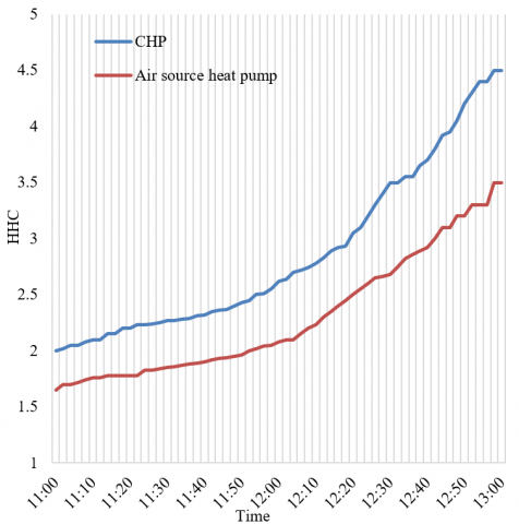
The energy efficiency values of the air source heat pump unit and the proposed CHP system when operating separately were compared and the results are shown in Figure 6. According to the figure, in the thermodynamic cycle at the initial operating stage, the heating coefficient was adopted to describe the two, and both curves were relatively flat, the reason is that the demand for hot water supply in the community at this stage was small, the flow of sewage was little, and the sewage source heat pump units in the CHP system had not been put into operation. Then, with the increase in the demand for hot water supply in the community, the sewage flow increased and the sewage source heat pump units had been put into operation, the heating coefficients of the air source heat pump units and the CHP system both grew steadily, but the energy efficiency of the CHP system had increased by about 23.5% compared with the situation when the air source heat pumps operated separately, which had again verified the good energy-saving effect of the proposed CHP system.
Figure 6. Comparison results of energy efficiency of heat pump systems
Table 3 gives the impact of sewage temperature drop on the performance indicators of the CHP system. According to the table, when the overall sewage in the community provides a fixed amount of heat, the decrease in sewage temperature has varying degrees of impact on the heating coefficient, the time required for heat recovery, and the electricity consumption of the CHP system. The impact on the electricity was the least, which indicated that no matter which equipment model had been chosen, the electricity consumption for recovering a certain amount of heat is basically the same. It can be seen from the figure, that the sewage temperature drop’s impact on the time required for heat recovery is the greatest, and its impact on the electricity consumption is the least. If the sewage temperature drop is relatively small, then machine units with smaller power could be chosen to reduce the input cost.
To verify the environmental performance of the CHP system, Table 4 lists the pollutant emission of different hot water supply systems, according to the table, the pollutant emission of the CHP system is only greater than that of the gas-fired boiler, and much smaller than other heating systems such as oil-fired boiler, coal-fired boiler, and electric heating system. Table 5 compares the performance of different hot water supply systems. Although the pollutant emission of the CHP system is not the lowest, its electricity consumption is very low and its heating efficiency is higher, and it doesn’t use liquefied gas, kerosene oil-gas, or other energies, therefore, the hot water supply method of the CHP system is the greenest.
Table 3. Impact of sewage temperature drop on the CHP system
|
Comparison condition |
The recovered heat was 1.31×10⁹KJ, and the electricity price of the day was 0.62 RMB/KWh. |
||||
|
Sewage temperature difference |
21℃ |
17℃ |
13℃ |
9℃ |
6℃ |
|
Sewage heat recovery |
735 |
708 |
572 |
375 |
301 |
|
Sewage source heat pump unit power |
185.3 |
175.6 |
157.5 |
96.4 |
75 |
|
Heating coefficient |
4.85 |
4.82 |
4.73 |
4.35 |
4.16 |
|
Available heat of the units |
963 |
835 |
735 |
482.3 |
358 |
|
Time required for heat recovery |
3.95 |
4.36 |
5.12 |
7.81 |
9.56 |
|
Electricity consumption |
752.6 |
802 |
835 |
753 |
798 |
|
Electricity charge |
508 |
512 |
542 |
501 |
512 |
Table 4. Pollutant emission of different hot water supply systems
|
Hot water supply system type |
Smoke and dust |
SO2 |
NOx |
CO |
CO2 |
|
Gas-fired boiler |
25.68 |
54.72 |
158.38 |
0.53 |
165824 |
|
CHP system |
753.38 |
1759.35 |
1328.6 |
13.41 |
215029 |
|
Oil-fired boiler |
96.51 |
3217.9 |
712.57 |
18.25 |
253125 |
|
Coal-fired boiler |
1132 |
2735.6 |
627.6 |
35.97 |
325810 |
|
Electric heating system |
2536.2 |
6532.1 |
5634 |
57.34 |
865321 |
Table 5. Performance of different hot water supply systems
|
Performance |
Coal-fired boiler |
Gas-fired boiler |
Solar heating system |
Electric heating system |
Sewage source heat pump |
|
Energy utilization |
Coal |
Natural gas |
Solar energy, electric energy |
Electric energy |
Electric energy |
|
Heating efficiency |
62 |
74 |
53 |
85 |
359 |
|
Energy consumption |
2.9kg |
1.75m3 |
2.82kWh |
46.27kWh |
12.5kWh |
|
Equipment safety |
Unsafe |
Unsafe |
Safe and reliable |
Potential hazard of electric leakage |
Safe and reliable |
|
Environmental impact |
Serious |
Average |
No pollution |
No pollution |
No pollution |
This study integrated the mature air source heat pump technology with the sewage source heat pump technology and conducted a research on the smart community waste heat recovery system based on the CHP system. At first, this paper designed the structure of the CHP system, gave the design steps of the CHP-based smart community waste heat recovery system including the design of the air source heat pump system, the design of the sewage source heat pump system, the model selection of related components, and the design of the control system. Then, this paper calculated the waste heat utilization rate of the CHP system, and experiments gave the calculation results of the investment and operation costs of the proposed CHP system; based on the pressure-enthalpy curve of the system, the performance indicators of the thermodynamic cycle of the system were calculated. At last, the operating status and energy efficiency of the CHP system and other heat pump systems were compared, and the energy-saving effect of the CHP system had been verified, the research findings of this paper provided a useful reference for the application of the CHP system in other occasions.
This work is supported by Talent Training Model for Higher Vocational Colleges under Modern Apprenticeship System in the Context of Military-Civilian Integration (Grant No.: HB19JY008).
[1] Mateu-Royo, C., Arpagaus, C., Mota-Babiloni, A., Navarro-Esbrí, J., Bertsch, S.S. (2021). Advanced high temperature heat pump configurations using low GWP refrigerants for industrial waste heat recovery: A comprehensive study. Energy Conversion and Management, 229: 113752. https://doi.org/10.1016/j.enconman.2020.113752
[2] Liew, P.Y., Walmsley, T.G. (2016). Heat pump integration for total site waste heat recovery. Chemical Engineering Transactions, 52: 817-822. https://doi.org/10.3303/CET1652137
[3] Wu, X., Xing, Z., He, Z., Wang, X., Chen, W. (2016). Performance evaluation of a capacity-regulated high temperature heat pump for waste heat recovery in dyeing industry. Applied Thermal Engineering, 93: 1193-1201. https://doi.org/10.1016/j.applthermaleng.2015.10.075
[4] Zhou, H., Du, X., Zhang, Z., Huang, Y. (2015). Heat pump CPCS-RBF predictive control based on multiple boundary conditions in circulating water waste heat recovery system. Proceedings of the Chinese Society of Electrical Engineering, 35(3): 645-651. https://doi.org/10.13334/j.0258-8013.pcsee.2015.03.018
[5] Shu, G., Yu, Z., Liu, P., Xu, Z., Sun, R. (2018). Potential of a thermofluidic feed pump on performance improvement of the dual-loop Rankine cycle using for engine waste heat recovery. Energy Conversion and Management, 171: 1150-1162. https://doi.org/10.1016/j.enconman.2018.06.011
[6] Arnaudo, M., Dalgren, J., Topel, M., Laumert, B. (2021). Waste heat recovery in low temperature networks versus domestic heat pumps-A techno-economic and environmental analysis. Energy, 219: 119675. https://doi.org/10.1016/j.energy.2020.119675
[7] Farshi, L.G., Khalili, S., Mosaffa, A.H. (2018). Thermodynamic analysis of a cascaded compression–absorption heat pump and comparison with three classes of conventional heat pumps for the waste heat recovery. Applied Thermal Engineering, 128: 282-296. https://doi.org/10.1016/j.applthermaleng.2017.09.032
[8] Jabari, F., Mohammadi-Ivatloo, B., Li, G., Mehrjerdi, H. (2018). Design and performance investigation of a novel absorption ice-making system using waste heat recovery from flue gases of air to air heat pump. Applied Thermal Engineering, 130: 782-792. https://doi.org/10.1016/j.applthermaleng.2017.11.015
[9] Liu, C., Jiang, Y., Han, W., Kang, Q. (2018). A high-temperature hybrid absorption-compression heat pump for waste heat recovery. Energy Conversion and Management, 172: 391-401. https://doi.org/10.1016/j.enconman.2018.07.027
[10] Yang, W.W., He, Y.L., Zhou, F., Yan, F.Y. (2017). Research on zeotropic mixtures as working fluid of high temperature heat pump for waste heat recovery. Journal of Engineering Thermophysics, 38(5): 907-913.
[11] Dehghan, B. (2017). Performance assessment of ground source heat pump system integrated with micro gas turbine: Waste heat recovery. Energy Conversion and Management, 152: 328-341. https://doi.org/10.1016/j.enconman.2017.09.058
[12] Meng, F., Zhang, H., Yang, F., Hou, X., Lei, B., Zhang, L., Wu, Y., Wang, J., Shi, Z. (2017). Study of efficiency of a multistage centrifugal pump used in engine waste heat recovery application. Applied Thermal Engineering, 110: 779-786. https://doi.org/10.1016/j.applthermaleng.2016.08.226
[13] Myagmarjav, O., Ryu, J., Kato, Y. (2015). Waste heat recovery from iron production by using magnesium oxide/water chemical heat pump as thermal energy storage. ISIJ International, 55(2): 464-472. https://doi.org/10.2355/isijinternational.55.464
[14] Pan, M., Lu, F., Zhu, Y., Huang, G., Yin, J., Huang, F., Chen, G., Chen, Z. (2020). Thermodynamic, exergoeconomic and multi-objective optimization analysis of new ORC and heat pump system for waste heat recovery in waste-to-energy combined heat and power plant. Energy Conversion and Management, 222: 113200. https://doi.org/10.1016/j.enconman.2020.113200
[15] Bamigbetan, O., Eikevik, T. M., Nekså, P., Bantle, M., Schlemminger, C. (2019). The development of a hydrocarbon high temperature heat pump for waste heat recovery. Energy, 173: 1141-1153. https://doi.org/10.1016/j.energy.2019.02.159
[16] Deymi-Dashtebayaz, M., Valipour-Namanlo, S. (2019). Thermoeconomic and environmental feasibility of waste heat recovery of a data center using air source heat pump. Journal of Cleaner Production, 219: 117-126. https://doi.org/10.1016/j.jclepro.2019.02.061
[17] Li, P., Gu, B., Miao, M.H. (2019). experimental research on waste-heat recovery heat pump system in electric vehicles. Journal of Shanghai Jiaotong University, 53(4): 468-472. http://xuebao.sjtu.edu.cn/EN/Y2019/V53/I4/468
[18] Cao, X.Q., Yang, W.W., Zhou, F., He, Y.L. (2014). Performance analysis of different high-temperature heat pump systems for low-grade waste heat recovery. Applied Thermal Engineering, 71(1): 291-300. https://doi.org/10.1016/j.applthermaleng.2014.06.049
[19] Zhang, H., Zhao, H., Li, Z. (2019). Waste heat recovery and water-saving modification for a water-cooled gas-steam combined cycle cogeneration system with absorption heat pump. Energy Conversion and Management, 180: 1129-1138. https://doi.org/10.1016/j.enconman.2018.11.051
[20] Singh, A., Sarkar, J., Sahoo, R.R. (2020). Experiment on waste heat recovery‐assisted heat pump drying of food chips: Performance, economic, and exergoeconomic analyses. Journal of Food Processing and Preservation, 44(9): e14699. https://doi.org/10.1111/jfpp.14699
[21] Han, X., Zou, H., Wu, J., Tian, C., Tang, M., Huang, G. (2020). Investigation on the heating performance of the heat pump with waste heat recovery for the electric bus. Renewable Energy, 152: 835-848. https://doi.org/10.1016/j.renene.2020.01.075