Niranjan Ramendra Singh* | Singh Onkar | Janakarajan Ramkumar
© 2021 IIETA. This article is published by IIETA and is licensed under the CC BY 4.0 license (http://creativecommons.org/licenses/by/4.0/).
OPEN ACCESS
Thermal management of the new generation’s high performance electronic and mechanical devices is becoming important due to their miniaturization. Conventionally, the plate fin arrangement is widely used for removal of dissipated heat but, their effectiveness is not up to mark. Among different options, the most attractive and efficient alternative for overcoming this problem is micro pin fin heat sink. This paper presents the experimental investigation of square micro-pin fins heat sink for identifying the most suitable pin fin geometry for heat removal applications under forced convection. Twenty five square micro pin fin heat sinks were tested for three different heat load and Reynolds number. The results show that for large fin height lower thermal resistance was observed at the cost of large pressure drop. The dimensionless heat transfer coefficient increases with fin height and Reynolds number while it decreases with increasing fin spacing. The improvement in micro pin fin efficiency were observed by about 2 to 9% owing to presence of fins on the impingement surface, flow mixing, disruption of the boundary layers, and augmentation of turbulent transport.
micro pin-fins, forced convection, heat transfer enhancement, fin effectivity
Heat generation during functioning of the various engineering components necessitates a suitable mechanism for its’ dissipation to maintain the device at a preferable temperature for its optimal working. The thermal management or heat dissipation system is the key to avoid the overheating of the components [1]. Hence, the enhancements of heat transfer rate are essentially required to control the working temperature. For enhancement of heat transfer between heat emitting devices to the surrounding atmosphere, the extended surface techniques are commonly used in the conventional macro system [2]. Similar configurations are used for thermal enhancement in the micro-scale systems typically in electronic equipment, electrical transformers, heat exchangers, chemical processing system, etc.
However, the effective thermal management of the electronic components is more vital to ensure their efficiency and reliability. Therefore, micro heat sink devices which maximize the thermal dissipation rate alongwith minimum pressure drop across the device need to be designed and optimized [3]. Micro pin fin array has the potential to fulfill the current demands due to their characteristic dimension of tens to hundreds of micrometers to provide the larger heat transfer area to volume ratios.
This concept was first introduced by Tuckerman and Pease [4], who designed a water cooled micro channel integrated heat sink for the power density of 790 W/cm2. Since then, numerous research has been carried out experimentally and numerically, to provide a significant amount of information in the field of microscale fluid flow and heat transfer process. Some of the previous literature in context to present work are summarized in Table 1.
Table 1. Summary of previous investigations
|
Authors |
Flow conditions & Geometry |
Study |
Results |
|
Soodphakdee et al. [3] |
Laminar flow Plate fin and Pin fin: square, circular, elliptical Numerical analysis |
The thermal performance of different pin fin heat sinks were numerically compared and discussed the advantages of elliptical pin fin over other geometry. |
Heat transfer performance of staggered geometries better than inline. Elliptical fins the efficiently at lower pressure drop and pumping power while circular pin fins gives highest performance at higher values. |
|
Şara [2] |
Re: 10000-34000 Staggered square pin fins Experimental Analysis |
The performance of staggered and inline arrangement of square pin fins array was experimentally analyzed. |
Flow and thermal performance of staggered square pin fins were increases with decreasing clearance ratio or increasing fin height. |
|
Khan et al. [5] |
Staggered arrangement velocity (m/s): 0.35, 2.49 Inline arrangement velocity (m/s): 3.04, 4.94 Cylindrical pin fin Numerical analysis |
Optimizing the geometric parameters, material properties for pin fin and flow conditions along with entropy generation rate. |
Staggered arrangement in all cases have higher entropy generation rate except higher thermal conductivity of material. |
|
Kobus and Oshio [6] |
Re: upto 200 Natural convection and combined forced and natural convection fin bundle Theoretical and Experimental Analysis |
Theoretical model for pin fin heat sink was developed to predict thermal performance and model was validated with experimental results. |
The experimental data of different fin array heat sink was used to verify the predictive capability of theoretical model for wide range of fin and base parameter. |
|
Peles et al. [7] |
Re: 10-1000 micro pin fins Analytically and Experimental Analysis |
The thermal performance of microscale pin fin heat sink were analzed analytically and experimently. |
Microscale cylindrical pin fin array gives superior thermo-hydraulic performance over plain micro channel. At higher Re convective thermal resistance of dense pin fin configuration are lower and vice-versa. |
|
Khan et al. [8] |
Re: upto 4000 Rectangular plate, square, circular and elliptical pin fin Theoritical Analysis |
The merits and demerits of pin fin geometry was graphically analysed and discussed the effect of Reynolds number, aspect ratio and axis ratio of pin fin on minimum entropy generation rate. |
Circular pin fin geometry performs better than the square geometry from the point of view of total entropy generation rate for lower Re. whereas, elliptical geometry are most suitable for higher Re. |
|
Joo and Kim [9] |
plate-fin and pin-fin |
In this study, design of pin fin array was optimized with the help of new developped correlation and compared with plate fin heat sink. |
A new correlation was suggested for convective heat transfer and a region map was given. |
|
Hirasawa et al. [10] |
Re = 8980, 26900 and 89800, Forced convection Diamond-shaped fin-array |
Thermal and hydraulic performance of daimond shape of fin array was analysed numerically and experimentally under forced convection. |
Experimental results were compared with numerical results and found that calculated Nu is higher than the experimental values. Further, a flip-flop flow phenomena was observed in numerical analysis however, it was absent in experimental results. |
The thermal performance of the rectangular pin fin array heat sink was experimentally investigated under turbulent flow condition by Ehteshum et al. [11] and shows improvement in heat transfer coefficient due to perforations with varying sizes and numbers. Further, the effect of the number and distribution of pin fin perforations on the heat transfer and pressure drop was numerically studied and validated experimentally [12].
For the first time, the thermal performance of micro fins was effectively analysed and measured in terms of heat transfer coefficient, fin effectiveness and mass specific heat transfer [13]. The squared micro-fins heat sink of 5 cm wide was studied and optimized for different power input and their thermal performance was compared with the plate fins. Based on the experimental results a correlation was developed between fin thickness and heat transfer. This new correlation is proposed to calculate the Nusselt number in micro fins application [14]. Micheli et al. [15] developed a 3D model of a previous experimental investigation to predict the thermal behavior of a micro finned concentrating photovoltaic, CPV system under natural convection conditions. Further, experimental study was performed to compare the thermal performance of micro-scaled plate fins with pin fins under natural convection. In an another study a novel simplified method has been proposed to determine the view factor of the pin fin [16].
The micro fins on a horizontal flat surface was thermally analyzed and optimized under natural convection. A variation up to 50% was observed in the mass specific heat transfer coefficient, which characterizes the effect of micro fins on the weight of the heat sink [17].
The thermal performance of perforated-finned heat sinks (PFHS) was experimentally investigated based on pumping power by Shaeri et al. [18] under natural to forced convection. The effect of porosities and perforation sizes on the heat transfer coefficient was evaluated and found a higher heat transfer coefficient for large number of perforations of small size. Further, effect of dimensionless geometrical parameters of laterally perforated-finned heat sink (LA-PFHSs) was experimentally analyzed to understand the thermo-fluid transport phenomena. With the help of these parameters, a correlation was developed to calculate the heat transfer coefficient of LA-PFHSs [19]. In addition, the laminar thermal performances of LA-PFHSs was experimentally compared with the solid-finned heat sink (SFHS) for same pumping power. The results show that LA-PFHSs have excellent thermal management [20].
Sakanova [21] studied the 3D conjugate heat transfer in perforated heat sink under aerospace conditions. Liquid and gas coolant such as water, oil, fuel, and air was used under laminar and turbulent conditions. The author reported that under laminar and turbulant flow perforated pin fin heat sink shows exceleent cooling performance over solid pin fin heat sink.
The annular fins over the tubes are widely studied by numerous authors in their previous research. However, there are limited investigations found for square fins. Therefore, Karami et al. [22] experimentally studied square finned tube heat exchangers of varying fin spacing under natural convection. The authors found that the 9 mm fin spacing provides the desired range of fin effectiveness (12.8-17.8).
Further, a numerical and experimental study was conducted under forced convection, to check the effect of pressure drop, temperature distribution and level of perforation on thermal characteristic of solid and perforated pin-fins heat sink. The result shows 1-4% improvement in the thermal efficiency of perforated pin fins compared to solid pin fins heat sink [23]. In the present investigation the thermal characteristics of the square micro pin fin heat sink was analyzed in terms of dimensionless heat transfer coefficient, fin effectiveness and thermal resistance. Design of micro pin finned arrays was optimized by varying the micro pin fin height and spacing for three power loads.
2.1 Heater and heat sinks
In the present experimental investigation, 25 sample of micro pin fin heat sinks was analyzed under forced convection. Each sample was made on a rectangular stainless steel plate (density 8027.2 Kg per m3, thermal conductivity 21 Wm-1 K-1) of dimension 147 mm (±1 mm) × 23.5 mm (±0.5 mm) wide, 1.4 mm thick; through Epilog Laser Fiber machine. Heat sink contains 13,432-14,208 number of square micro pin fins, as shown in Figure 1 and the micro pin fin dimensions are given in Table 2.
Figure 1. Schematic view of the square micro pin fin arrays
Table 2. Dimensions of square Pin Fin array for each sample
|
Sample No. |
Fin spacing, s (μm) |
Fin Height, Hf (μm) |
Fin thickness, t (μm) |
|
1-1 |
28 |
3.50 |
472 |
|
1-2 |
34 |
466 |
|
|
1-3 |
37 |
463 |
|
|
1-4 |
39 |
461 |
|
|
1-5 |
45 |
455 |
|
|
2-1 |
18 |
5.50 |
482 |
|
2-2 |
26 |
474 |
|
|
2-3 |
42 |
458 |
|
|
2-4 |
50 |
450 |
|
|
2-5 |
53 |
447 |
|
|
3-1 |
20 |
7.10 |
480 |
|
3-2 |
30 |
470 |
|
|
3-3 |
35 |
465 |
|
|
3-4 |
43 |
457 |
|
|
3-5 |
58 |
9.00 |
442 |
|
4-1 |
45 |
455 |
|
|
4-2 |
53 |
447 |
|
|
4-3 |
57 |
443 |
|
|
4-4 |
60 |
440 |
|
|
4-5 |
72 |
428 |
|
|
5-1 |
50 |
11.30 |
450 |
|
5-2 |
55 |
445 |
|
|
5-3 |
59 |
441 |
|
|
5-4 |
65 |
435 |
|
|
5-5 |
75 |
425 |
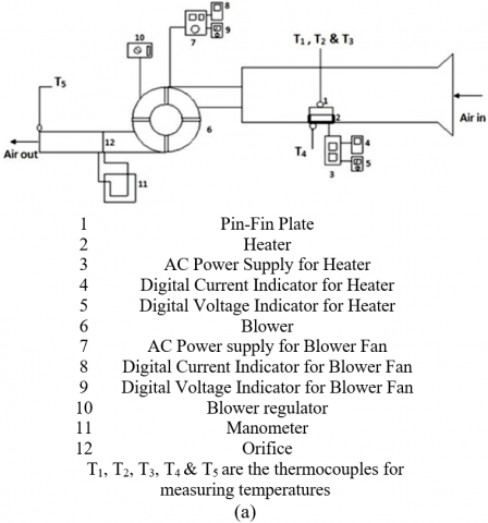
65W AC electrical heater was used to heat micro pin fins heat sink. Heater was kept in an insulating case made of steel whose three sides were covered with thick glass wool of thermal conductivity: 0.04 Wm-1K-1. Further, casing was insulated through a thick layer of polystyrene. The heat losses by convection and radiation are only through the top surface of the heater and these losses are taken into account. This whole assembly (heat sink and heater with insulated case) was placed inside the rectangular wind tunnel duct as shown in Figure 2.
Figure 2. (a) Experimental setup; (b) Schematic view of heat sink
2.2 Rectangular wind tunnel duct
The schematics view of the experimental setup is shown in Figure 2. An experimental setup consist of rectangular wind tunnel duct, made of mild steel. The air is admitted to the rectangular duct using an electrical driven fan with variable speed, to control the airflow rate. The dimensions of the rectangular wind tunnel duct are 45cm x 15cm × 10cm.
2.3 Measurement equipment
The experimental setup was operated for three different Reynolds Numbers. The duct air flow rate was measured indirectly through a manometer (manometric fluid – Glycerine, density 1.26 g/cm3) and regulated via blower regulator. The pressure drops across the heat sink was evaluated indirectly through fan power. The blower fan power was controlled by adjusting the voltage through variac (auto transfer- continuously variable 0-260 volt). A auto range digital multimeter SM7022 (current range- 0-10 amp and voltage range- 0-1000 volt) was used to measured the electric current and voltage. Further, temperature of the heating coil was controlled through adjusting the voltage by variac. In the present investigation three power inputs of 40 V, 60 V, and 80 V resembled heating power intensities 1.1 kW/m2, 2.2 kW/m2 and 3.6 kW/m2 respectively was applied to the heating coil. The heat produced by heating coil was estimated through the measurement of electric current and voltage by using two digital multimeters of make MTC and Yokins respectively. The surface temperatures of the micro pin fin heat sink was measured via two measuring instruments, K type thermocouples (accuracy ±0.75℃) and HTC infrared thermometer (MT-6). The ambient temperature was maintained at 25℃ and continuously measured by a K-type thermocouple. In the experimentation, it was assumed that temperature was constant throughout the heat sink and the fin height. All the experiments were performed three times and data were taken at the steady-state condition.
2.4 Experimental procedure
The experiment was started by setting up all electrical connections and the heater was switched on for some period of time to achieve a steady-state. After some time blower was switched on to make airflow in the duct to attain steady state. Pressure drops across the micro pin fin heat sink were measured for three Reynolds numbers 4800, 5300 and 5900. All properties of associated fluids and materials are taken at an average temperature of the micro pin fin surface and the bulk air.
2.5 Analytical method
The heat loss from the heat sink can be evaluated at steady-state as follows,
Qelec = Qconv + Qrad + Qcond (1)
Heat loss through radiation Qrad in a micro pin fin array was negligible compared to the convective loss Qconv.
Here, it was assumed that the heat loss through conduction, Qcond in glass wool insulation was negligible and convective heat loss through micro pin fin heat sink only.
The convective heat transfer coefficient h, Nusselt number, Nu and thermal resistance, Rth are determined by the following equation,
Qconv. = h.Afins.(Tfins - Tamb) (2)
$\mathrm{Nu}=\frac{h . l}{k}$ (3)
Rth = 1/(h.Afins) (4)
The average velocity inside the rectangular wind tunnel duct was calculated using the effective fluid flow area, A –Afront (perpendicular to the airflow direction).
$v_{\text {avg }}=\frac{A \cdot v}{A-A_{\text {front }}}$ (5)
The Reynolds number, Re in the duct is calculated as fallows,
$\mathrm{Re}=\frac{v_{a v g}. d_{h}}{v}$ (6)
Fin effectiveness, ɛfin is defined as,
$\varepsilon_{f i n}=\frac{Q_{f}}{Q_{p}}$ (7)
The blower fan power equation was used to estimate the pressure drop (∆P) across the heat sink,
Pfan = vavg.As. ∆P (8)
where, As is the flow channel area over the heat sink evaluated by the following equation,
As= tf.S.(NL-1) (9)
2.6 Measurement uncertainty
To assess the accuracy of the present experiment uncertainty analysis was performed. The overall uncertainty of a calculated parameter based upon the measured value is calculated accordingly to the propagation of error for independent variables:
|
$U_{p}=\sqrt{\sum_{i=1}^{n}\left(\frac{\partial p}{\partial a_{i}} u_{a i}\right)^{2}}$ |
p |
Calculated parameter |
|
ai |
Variable use to calculate p |
|
|
uai |
Uncertainty of the variable ai |
The experimental uncertainty of heat transfer coefficient of micro pin fins based upon actual measured parameter is given by:
$\frac{U h_{\text {fins }}}{h_{\text {fins }}}=\sqrt{{\left(\frac{U Q_{\text {fins }}}{Q_{\text {fins }}}\right)^{2}+\left(\frac{U A_{\text {fins }}}{A_{\text {fins }}}\right)^{2}}\\+\left(\frac{U T_{\text {fins }}}{T_{\text {fins }}-T_{\text {amb }}}\right)^{2}+\left(\frac{U T_{a m b}}{T_{\text {fins }}-T_{\text {amb }}}\right)^{2}}$ (10)
The micro pin fin surface was measured with an uncertainty of ±0.2%. Micro pin fin temperature, Tfins was measured by two instruments, k type thermocouple, and HTC infrared thermometer, which have an uncertainty of measurement ±2% and ±0.2% respectively. Ambient temperature, Tamb was obtained by the averaging the readings of the thermocouples. In the preliminary investigation offset measured in the temperature data of uncertainty of ±1.0℃ was used to adjust succeeding data. The maximum experimental uncertainty was found to be ±9.50% close to the range reported by Al-Damook et al. [12].
3.1 Pressure drop
The effect of micro pin fin spacing and fin height on the pressure drop for all the configurations can be seen in Figures 3(a) to 3(c). It is known that form drag and friction drag becomes significant across the micro pin fin array and causes a pressure drop. Both of the drag components increase with the square of velocity. Therefore total pressure drop will increase with increase velocity i.e. Reynolds number. However, in the present case pressure drops minutely increase due to the very small size of pin fin.
Figure 3. Variation in pressure drop
For constant fin spacing, height and width it increases 7.01% - 8.30% for the increase in Reynolds number from 4,800 to 5,900. This is clearly shown in Figures 3(a) to 3(c). Further, it is evident from the figure that the pressure drops decreases with pin fin spacing and increases with pin fin height. It was observed to be occurring due to a decrease in drag components because fin dimension decreases as fin spacing increases. Fins with spacing and width of 45 µm and 455 µm respectively the pressure drop was about 2.46% higher as compared to fin spacing and width of 55 µm and 445 µm at constant fin height 7.1 µm. In addition, the pressure drop was affected by the fin height and it was observed that pressure drop increases to 5.36% for fin height increasing from 5.5 µm to 9.0 µm for constant fin spacing (50 µm) and constant fin width (450 µm). The bigger fins express large pressure drop, which is probably due to more disturbances in the fluid has within the channel.
3.2 Thermal resistance
The effect of micro pin fin spacing on the thermal performance of the heat sink is shown in Figures 4(a) to 4(c). As expected, the thermal resistance increases with increasing fin spacing and decreases with fin height. Increasing the fin height increases the heat transfer area, therefore, cooling enhances. While an increase in the fin spacing leads to decrease in the heat transfer area. Further, it is evident from Figures 4(a) to 4(c) that Reynolds number affects the thermal resistance. It was observed that thermal resistance decreases with increasing Reynolds number.
Figure 4. Variation in thermal resistance
For constant fin spacing and height, the thermal resistance decreases from 7.0% to 15.0% for an increase in Reynolds number from 4,800 to 5,900. This is clearly shown in Figures 4(a) to 4(c). Fins with spacing and width of 45 µm and 455 µm the thermal resistance was about 0.3% - 1.2% lower compared to fin spacing and width of 55 µm and 445 µm at constant fin height 7.1 µm. In addition, the thermal resistance was affected by the fin height and it was observed that thermal resistance decreases 2.0% - 4.22% for fin height increasing from 5.5 µm to 9.0 µm for constant fin spacing (50 µm) and constant fin width (450 µm).
3.3 Dimensionless heat transfer coefficient
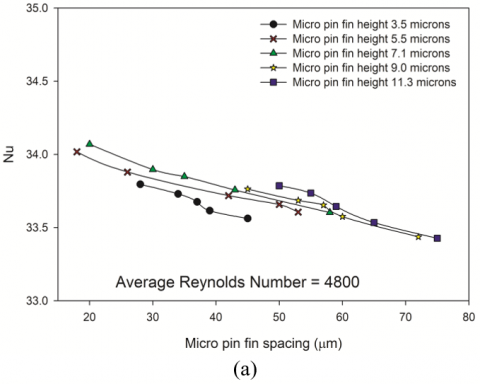
Figures 5(a) to 5(c) shows the variation in dimensionless heat transfer coefficient (Nusselt number, Nu) due to fin spacing and fin height. It was observed that fin spacing and fin height yields the opposite effect on the Nu. The Nu increases with decreasing fin spacing and increases with increasing fin height. Further, results show that the Nu increases with Re. The maximum value of Nusselt number (≈ 38) was found at Reynold Number 5,900 for fin spacing 20 µm and fin height 11.3 µm. The Nusselt number varies between 10 - 12% for the Reynold number range 4,800 – 5,900 and 1.3 -1.6% for fin spacing 20 µm – 75 µm for fin height 7.1 µm. For other fin heights nearly similar results were obtained. This could be because of thicker thermal and hydrodynamic boundary layer getting formed at each fin sections with increasing fin spacing which, was independent of any upstream effects.
Figure 5. Variation in Nusselt number
3.4 Fin effectivity
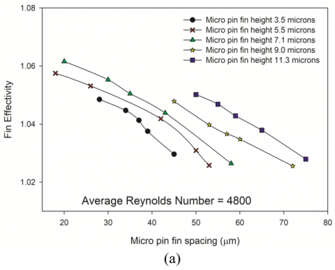
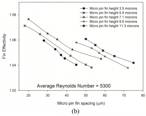
The aim of this experimental study is to find the optimum pin fin height and spacing that would enhance the heat removal rate while minimizing the frictional losses in the flow. A parametric optimization was performed on pin fin heat sink at various fin height and fin spacing with constant Reynolds number. The effect of pin fin spacing and pin fin height on fin efficiency is shown in Figures 6(a) to 6(c). It is clearly evident from figures that upon decreasing the fin spacing or increasing the fin height, fin efficiency increases.
Figure 6. Variation in fin effectivity
This can be attributed to the decrease in the volume of air enclosed between fins with decrease in fin spacing leading to reduction in resistance due to air while surface area increases. Therefore, for higher-conductive fin material the fins works efficiently and enhance the heat removal rate i.e. fin effectivity. In the present experimental investigation, 2 to 9% enhancement in the fin effectivity was found along with 8 to 10% increase in heat transfer. However, no clear cut relationships have been found between fin effectiveness and fin geometry.
Further, Figures 6(a) to 6(c) represent the effect of Reynolds number on fin efficiency. It was observed from the graphical results that the efficiency increases with Reynolds number due to higher heat transfer rate.
3.5 Surface maximum temperature
The physical characteristics of the micro square pin-fin heat sink can be assessed by the cooling capacity of the micro square pin-fin.
In the current investigation three different heat flux, heating power intensities 1.1 kW/m2, 2.2 kW/m2 and 3.6 kW/m2 were applied to the heat sink and the cooling capacity of the heat sink was estimated by measuring the surface maximum temperature at four different locations. The average surface maximum temperature was plotted in Figures 7(a) to 7(c) with pin fin spacing and fin height. It is well known that the cooling capacity of the heat sink gets affected by heat transfer. It is clearly seen from the Figures 7(a) to 7(c) that the heat transfer rate i. e. cooling capacity enhances as fin spacing decreases or fin height increases due to an increase in surface area. From the graphical depiction of results it can be seen that for fin height of 7.1 µm, the fin surface temperature (Tmax) got reduced from 336 K to 332 K when fin spacing reduced from 60 µm to 20 µm at constant Reynolds number (5900) and constant heat flux (3.6 kW/m2). Further, similar observations were found for other fin heights i. e. temperature drops with the increase of the pin-fin height or decrease of pin fin spacing. It is clearly seen from the figures that at smaller heat flux, the surface maximum temperature of the heating surface is lower and it was found in the range of 310 K to 311K for fin spacing of 60 µm to 20 µm at constant fin height (7.1 µm). The maximum temperature Tmax of the heat sink surface indicates the effect of pin fin height and fin spacing on the cooling capacity. As depicted in Figure 7, the surface maximum temperature is lower, which demonstrates better performance of the pin-fin structure.
Figure 7. Variation in maximum surface temperature
The thermal performance of micro pin fin has been studied experimentally because heat transfer from the extended surface is more complex at the micro-scale. The following conclusions have been drawn from this study.
The decrease in the fin spacing or increase in the fin height increases the exposed surface area for the flow which promotes turbulence. Therefore, thermal resistance decreases due to the absence of the bypass effect but results in a slightly higher pressure drop.
Further, a similar observation was observed as above for fixed fin spacing on increasing the pin fin height.
The thermal performance and cooling capacity of heat sinks were effectively enhanced by decreasing the pin fin spacing or increasing the pin fin height. The fin effectivity in forced convection can be as high as 1.10 but the correlation between it and the fin geometry has yet to be sorted out.
Further, it was found that the thermal management and cooling capacity of the micro heat sink are slightly more sensitive to pin-fin height compared to the pin-fin spacing.
The Nusselt number increases with decreasing fin spacing or increasing pin fin height as a result of more frequent interruption of the thermal boundary layer.
From the present investigation, it was observed that the micro square pin-fin heat sink is more useful for the cooling of high-density power chips. The thermal enhancement of the micro heat sink is also effectively altered by varying the pin-fin height and spacing.
The authors gratefully acknowledge the research facility provided by the Department of Mechanical Engineering, IIT Kanpur. The authors are also thankful to Dr Abhishek Kumar Chandra, UIET, CSJM University Kanpur for valuable guidance and support.
|
A |
cross-sectional area of the duct, mm2 |
|
Afront |
front area of the heating setup including heat sink, mm2 |
|
Afins |
area of fined surface, mm2 |
|
Ap |
cross-sectional area of plate fin, mm2 |
|
C |
remaining height in the duct or space after placing the heating setup with heat sink, mm |
|
dh |
hydraulic diameter of channel, mm |
|
h |
heat transfer coefficient, W/m2K |
|
hf |
convective heat transfer coefficient of micro pin fin array, W/m2K |
|
hp |
convective heat transfer coefficient of plate fin, W/m2K |
|
H |
height of the heating setup with heat sink in the duct, mm |
|
k |
thermal conductivity of air, W/mK |
|
l |
characteristic length of fins, mm |
|
NL |
number of micro pin fin perpendicular to fluid flow |
|
Nu |
Nusslet number |
|
Qconv |
heat dissipated in convection mode from micro pin fin array, W |
|
Qf |
heat transferred by convection from micro pin fin array, W |
|
Qcond |
heat loss in different mode through the insulating case, W |
|
QL |
power in input, W |
|
Qp |
heat transferred by convection from plate fin, W |
|
Qrad |
heat dissipated in radiation mode from micro pin fin array, W |
|
Re |
Reynolds number |
|
Rth |
thermal resistance of micro pin fin array, K/W |
|
S |
micro pin fin spacing, µm |
|
t |
square micro pin fin width, µm |
|
tb |
height of heat sink from bottom surface to un-fined surface, mm |
|
tf |
micro pin fin height, µm |
|
T |
temperature, K |
|
Tamb |
ambient temperature, K |
|
Tfins |
temperature of micro pin fin array surface, K |
|
Tp |
temperature of plate fin surface, K |
|
U |
total uncertainty |
|
v |
air inlet velocity, ms-1 |
|
vavg |
average velocity inside the channel, ms-1 |
|
W |
width of the micro pin fin array sample, mm |
|
∆P |
pressure drop, Pa |
|
Greek letters |
|
|
ɛf |
overall fin effectiveness |
|
v |
kinematic viscosity of air, m2s-1 |
[1] Oguntala, G., Alhameed, R.A., Sobamowo, G., Abdullahi, H.S. (2018). Improved thermal management of computer microprocessors using cylindrical-coordinate micro-fin heat sink with artificial surface roughness. Engineering Science and Technology, an International Journal, 21(4): 736-744. https://doi.org/10.1016/j.jestch.2018.06.008
[2] Şara, O.N. (2003). Performance analysis of rectangular ducts with staggered square pin fins. Energy Conversion and Management, 44(11): 1787-1803. https://doi.org/10.1016/S0196-8904(02)00185-1
[3] Soodphakdee, D., Behnia, M., Copeland, D.W. (2001). A comparison of fin geometries for heatsinks in laminar forced convection: Part I - Round, elliptical, and plate fins in staggered and in-line configurations. The International Journal of Microcircuits and Electronic Packaging, 24(1): 68-76.
[4] Tuckerman, D.B., Pease, R.F.W. (1981). High-performance heat sinking for VLSI. IEEE Electronic Devices Letters, 2(5): 126-129. https://doi.org/10.1109/EDL.1981.25367
[5] Khan, W.A., Culham, J.R., Yovanovich, M.M. (2004). Optimization of pin-fin heat sinks using entropy generation minimization. IEEE Transactions on Components and Packaging Technologies, 28(2): 247-254. https://doi.org/10.1109/TCAPT.2005.848507
[6] Kobus, C.J., Oshio, T. (2005). Development of a theoretical model for predicting the thermal performance characteristics of a vertical pin-fin array heat sink under combined forced and natural convection with impinging flow. International Journal of Heat and Mass Transfer, 48(6): 1053-1063. https://doi.org/10.1016/j.ijheatmasstransfer.2004.09.042
[7] Peles, Y., Koşar, A., Mishra, C., Kuo, C.J., Schneider, B. (2005). Forced convective heat transfer across a pin fin micro heat sink. International Journal of Heat and Mass Transfer, 48(17): 3615-3627. https://doi.org/10.1016/j.ijheatmasstransfer.2005.03.017
[8] Khan, W.A., Culham, J.R., Yovanovich, M.M. (2006). The role of fin geometry in heat sink performance. J. Electron. Packag., 128(4): 324-330. https://doi.org/10.1115/1.2351896
[9] Joo, Y., Kim, S.J. (2014). Comparison of thermal characteristics between the plate-fin and pin-fin heat sinks in natural convection. 10th International Conference on Heat Transfer, Fluid Mechanics and Thermodynamics, Orlando, Florida, pp. 174-178.
[10] Hirasawa, S., Fujiwara, A., Kawanami, T., Shirai, K. (2014). Forced convection heat transfer coefficient and pressure drop of diamond-shaped fin-array. Journal of Electronics Cooling and Thermal Control, 4(3): 78-85. https://dx.doi.org/10.4236/jectc.2014.43009
[11] Ehteshum, M., Mohammad, A., Mohammad, Q.I., Tabassum, M. (2015). Thermal and hydraulic performance analysis of rectangular fin arrays with perforation size and number. Procedia Engineering, 105: 184-191. https://doi.org/10.1016/j.proeng.2015.05.054
[12] Al-Damook, A., Kapur, N., Summers, J.L., Thompson, H.M. (2015), An experimental and computational investigation of thermal air flows through perforated pin heat sinks. Applied Thermal Engineering, 89: 365-376. https://doi.org/10.1016/j.applthermaleng.2015.06.036
[13] Micheli, L., Reddy, K.S., Mallick, T.K. (2015). Plate micro-fins in natural convection: Experimental study on thermal effectiveness and mass usage. International Conference on Polygeneration, ICP.
[14] Micheli, L., Reddy, K.S., Mallick, T.K. (2015). General correlations among geometry, orientation and thermal performance of natural convective micro-finned heat sinks. International Journal of Heat and Mass Transfer, 91: 711-724. http://doi.org/10.1016/j.ijheatmasstransfer.2015.08.015
[15] Micheli, L., Reddy, K.S., Mallick, T.K. (2015). Plate micro-fins in natural convection: An opportunity for passive concentrating photovoltaic cooling. Energy Procedia, 82: 301-308. http://doi.org/10.1016/j.egypro.2015.12.037
[16] Micheli, L., Reddy, K.S., Mallick, T.K. (2016). Experimental comparison of micro-scaled plate-fins and pin-fins under natural convection. International Communications in Heat and Mass Transfer, 75: 59-66. http://doi.org/10.1016/j.icheatmasstransfer.2016.03.023
[17] Micheli, L., Reddy, K.S., Mallick, T.K. (2016). Thermal effectiveness and mass usage of horizontal micro-fins under natural convection. Applied Thermal Engineering, 97: 39-47. http://doi.org/10.1016/j.applthermaleng.2015.09.042
[18] Shaeri, M.R., Richard, B., Bonner, R. (2016). Cooling performances of perforated-finned heat sinks. Proceedings of the ASME 2016 Heat Transfer Summer Conference, Washington, DC, USA. https://doi.org/10.1115/HT2016-7284
[19] Shaeri, M.R., Bonner, R. (2017). Effect of perforation size to perforation spacing on heat transfer in laterally perforated-finned heat sinks. Proceedings of the ASME 2017 Heat Transfer Summer Conference, Bellevue, Washington, USA. https://doi.org/10.1115/HT2017-5076
[20] Shaeri, M.R., Bonner, R. (2017). Heat transfer and pressure drop in laterally perforated-finned heat sinks across different flow regimes. International Communications in Heat and Mass Transfer, 87: 220-227. http://doi.org/10.1016/j.icheatmasstransfer.2017.07.022
[21] Sakanova, A. (2017). Heat transfer enhancement of perforated pin heat sink in future aircraft applications. Applied Thermal Engineering, 124: 315-326. http://doi.org/10.1016/j.applthermaleng.2017.06.031
[22] Karami, M., Yaghoubi, M., Keyhani, A. (2018). Experimental study of natural convection from an array of square fins. Experimental Thermal and Fluid Science, 93: 409-418. https://doi.org/10.1016/j.expthermflusci.2018.01.020
[23] Tijani, A.S., Jaffri, N.B. (2018). Thermal analysis of perforated pin-fins heat sink under forced convection condition. Procedia Manufacturing, 24: 290-298. https://doi.org/10.1016/j.promfg.2018.06.025