Vitaly V. Dubrovsky* | Aleksandr A. Shraiber
© 2020 IIETA. This article is published by IIETA and is licensed under the CC BY 4.0 license (http://creativecommons.org/licenses/by/4.0/).
OPEN ACCESS
The laws of heat exchange between air and a liquid film flowing down along a solid surface with spherical dimples were investigated experimentally. Three cases of heat transfer were considered: quiescent air, air – liquid counter flow, or their cross flow. In all cases, a significant growth of the heat exchange intensity, especially at air – liquid cross flow, was observed. This is caused by the substantial turbulization of flow and mixing of liquid layers in the film. As a result, it was established that surface profiling (manufacture of dimples) under the optimal conditions leads to an increase in heat exchange intensity by an unexpended factor of 2.5 – 2.8 as compared with a smooth surface, other conditions being equal. The obtained experimental data were generalized in the form of dimensionless dependences Nu vs. Re. The best heat transfer surface can be recommended for use in different heat exchangers.
profiled surface, spherical dimples, heat exchange, relative velocity, degree of cooling
Investigations of heat exchange between a liquid film and a gas are interesting for mixing heat exchangers, which are widely used in different branches of industry. Heat and mass transfer in such installations depends primarily on the intensity of processes of liquid mixing in its thin layers.
In the literature, one can find numerous works devoted to the intensification of heat exchange between a solid surface and a liquid flow along it due to the formation of indentations – dimples on the surface [1-10]. It was established that such surface profiling leads to the generation of non-stationary vortex structures in the flow, mixing of the liquid, and, as a result, noticeable intensification of heat exchange as compared with a smooth surface. The use of dimples is characterized by low pressure losses and high thermal-hydraulic efficiency. Such technology is successfully used in various heat-exchange installations, in particular, at cooling blades of gas turbines, elements of electronic equipment, etc.
The aim of this work was to study experimentally the heat exchange of a liquid film, flowing along a profiled solid surface, not with the wall along which it flows down, but with the surrounding gas environment as in contact heat exchangers, and to estimate the effect of surface profiling on the intensity of heat exchange. In the available literature, we did not find any works on heat exchange between a gas and a liquid flowing along a surface with dimples.
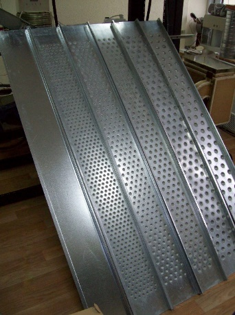
To study the influence of surface relief on the intensity of heat transfer from it to the surrounding air, we used six trays: five profiled (T30, T24, T20, T16, and T13) and one with a smooth surface T0 (Figure 1). The trays were made of sheets of galvanized steel of thickness 0.55 mm, length L = 1800 mm, and width l = 180 mm, bounded by small collars. Profiling was performed by the forging of spherical dimples, whose sizes are given in Table 1 and Figure 2 on the surfaces. The dimples of diameter D (in the plane of tray surface) and depth h were arranged in chess sequence with a distance S between the centers of dimples, where three adjacent dimples formed a regular triangle. The ratio between dimple depth and its diameter (h/D = 0.3) was chosen according to known results [2], where just such ratio gave the best heat transfer. For all types of trays, the conditions of geometric similarity of the dimples diameters, their depths, and distances between their centers were satisfied.
Figure 1. Experimental trays
Table 1. Geometrical characteristics of spherical dimples
|
Tray |
D, mm |
h, mm |
S, mm |
h/D |
|
T30 |
30 |
9 |
60 |
0.3 |
|
T24 |
24 |
7.5 |
49 |
|
|
T20 |
20 |
6 |
40 |
|
|
T16 |
16 |
5 |
32 |
|
|
T13 |
13 |
4 |
26 |
Figure 2. Diagram of the sizes of experimental trays
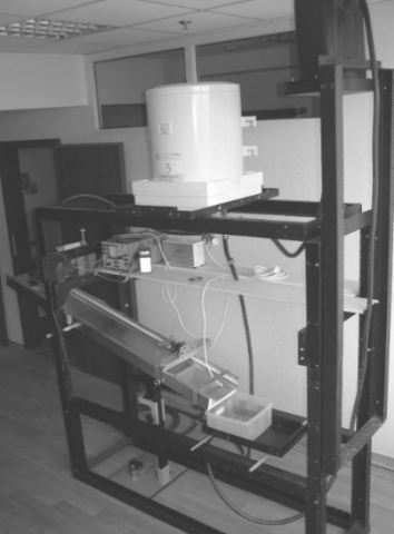
Figure 3. Picture of the experimental setup
Our measurements were carried out on a specially constructed experimental setup, the picture and scheme of which are presented in Figure 3 and Figure 4. An experimental tray 1 was mounted on a carcass, manufactured of special metal frames. Warm water from an industrial heater 2 through a valve 3, a flow meter 4, and a valve 5 was fed to the tray. Further, it flowed down as a film on the tray, came to a container 6, and, by means of a centrifugal pump 7, was fed into a vessel 8. From here, through a valve 9, water returned to heater 2, and, hence, it circulated in a closed circuit of setup. A valve 10 was used to fill the contour with water.
Water was warmed by a heating element 11, connected to an electronic thermal stabilizer 12, which, with the use of a temperature sensor 13, provided a stable water temperature at the outlet of heater 2. The valve 3 regulated water flow to the experimental tray 1 in order to achieve a certain thickness of the film on its surface. The temperature of water, fed directly to the tray, was controlled by a digital thermometer 14 with a temperature sensor 15, mounted in the upper flow section of the tray. The liquid film was cooled by heat exchange with air above it.
Before starting measurements in the circuit of water circulation, we established a thermo-stable flow regime. After that, the degree of film cooling was determined by the temperature difference between upper and lower sections of the flow. This value was measured by a high-precision differential digital thermometer 16, produced by corporation “Skifanalit” (Ukraine), with identical sensors 17 and 18, having a precisely linear dependence of resistance on temperature. The instrument has a commutator, which in turn connects an analog-to-digital converter to two sensors. The converter transforms the voltage drop on sensor into digital codes, which are fed to a microcontroller. The last with the help of a special program calculates the ratio between voltage drops on sensors and, based on calculations, transmits information on the temperature difference to a display. If the sensor temperatures are equal, the display shows zero. The calibration of sensors was performed at two points: temperature of snow thawing and 50°С. Our instrument provided measurements of temperature difference with an accuracy of 0.025°С in a temperature range of 20 – 50°С. The relative error of measurements even at a minimal temperature difference of 0.5°С was only 5%. Random errors were excluded by several measurements of temperatures at a certain constant regime, and the repeatability of measurement results was quite good.
Figure 4. Scheme of the experimental setup
The angle of tray inclination φ could be changed by using special devices. In this case, the position of trays could vary from horizontal to vertical, which enabled us to change the velocity of film flow. The lower and lateral surfaces of trays were thermally insulated for minimizing the heat transfer from liquid through the material of trays. When changing trays, the valve 5 was closed, and the valve 19 was opened, which enabled us to maintain a thermo-stable regime in the circuit.
In each experiment, the following quantities were measured: water temperature tu in the upper cross section of flow, difference Dt between its upper and lower cross sections (degree of cooling), air temperature tа above the tray, and liquid flow rate along it. For each experiment, we found the average water temperature in the tray tw = tu – Dt/2. Each series of experiments consisted of several measurements of all parameters, and then their averaged values were determined. After finishing the experiment with a profiled tray, it was replaced by a smooth one, and measurements were repeated, which made it possible to estimate the effect of surface profiling on heat transfer. The time interval between experiments with different trays was small (~ 2 minutes), and, hence, the experimental conditions were practically identical.
For each experiment, we determined the heat flux Q between film and air as well as the mean heat transfer coefficient a:
Q=c G Dt
a=Q/(F(tw–tа))
where, c is the specific heat of water, G is its mass flow rate, and F = l×L is the film surface area.
Experiments were carried out in the range of flow rates from 0.068 to 0.179 kg/s, at three flow lengths 1.7, 1.1, and 0.6 m, in the range of angles of tray inclination from 15 to 45 degrees to the horizon. As to the chosen liquid flow rates, the least its amount should cover the entire tray surface without ruptures.
The uncertainty of finding α is determined by the errors of measurements of the following quantities: cooling rate Dt (error is ε1 = 5%, see above), air temperature (ε2 = 1%), geometrical parameters (ε3 = 0.5%), liquid flow rate (ε4 = 2%), and kinematic viscosities for air and water (ε5 = ε6 = 0.5%). Hence, the values of α were determined with an error ≤ 10%, which is acceptable in heat – exchange experiments.
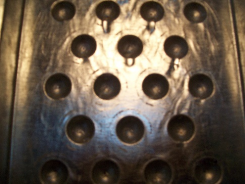
Figure 5. Features of water flow along the profiled tray T20 at G = 0.143 kg/s
Unlike a tray with a smooth surface, where only insignificant disturbances were observed, the nature of flow on profiled surfaces changed considerably, and quite high specific breakers were formed (Figure 5). Water distribution along the surface of trays with dimples is more uniform, and brooks practically were not observed. The presence of dimples changes the flow profile, turbulizes it, and circulating zones are formed in them. It is important that there are disturbances not only in the dimples themselves, but also between them on the smooth part of surface.
Thus, we have constructed an experimental setup and developed a procedure of the investigation of heat transfer between a gas and a liquid film flowing down along a surface with spherical dimples.
The first stage of our experiments was carried out with quiescent air over the film. We performed 108 series of experiments, 27 series each for smooth surface and three profiled trays T13, T20, and T30 (see Table 1).
Experiments showed that the presence of dimples leads to an unexpectedly high level of heat exchange intensification (Table 2) [11]. Here, the T20 tray was the best as to the degree of water cooling and heat transfer coefficient (trays T13 and T30 mm yield worse results). The surface with T20 dimples increases the heat transfer intensity by a factor of 2 – 2.8 (at different flow rates) and the cooling rate of 2 – 3.3 as compared with the smooth surface. The mechanism of heat exchange intensification lies here in the formation of flow around a small obstacle (intensifier) on the surface.
The effect of increasing the surface area due to the forging of dimples on heat transfer was also estimated. It turned out that the intensification of water – air heat exchange on surfaces with dimples is much greater than the increase in surface area due to dimples and, hence, cannot be explained only by the growth of contact surface.
Consider now the influence of different factors on heat transfer. Although small angles j of profiled tray inclination (15 deg and lower) increase the time of phase contact by reducing the film velocity, they lead to less cooling, because the flow turbulization deteriorates. With increase in the angle j, heat transfer becomes better, but, at j > 30 deg and especially at larger j, a lot of splashes is formed, which leads to certain errors in determining the heat transfer coefficient. Therefore, only angles of 15 to 30 deg were taken for further processing of experimental results. It was found that the optimal angle of tray inclination is 30 deg.
With increase in the tray length (i.e., increase in the time of contact between the phases), the degree of water cooling, naturally, increases (Figure 6). The dependence of coefficient a on the flow length is opposite to Dt: with length extension, the coefficient a decreases. This dependence has the same character as at the flow of a fluid along a flat surface [12]. In our experiments, this is caused by the thickening of boundary layer in air along the film, which leads to an increase in thermal resistance at the interface.
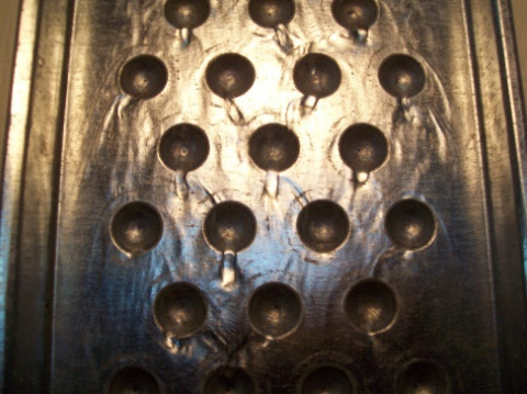
Since a change in the water flow rate in a tray with a fixed width causes a change in the film thickness, the flow hydrodynamics also varies. In Figure 7, we show the character of flow on the T20 tray depending on G (on the photo, the film flows from top to bottom). For different film thicknesses, the picture of flow is somewhat different. The flow of a film of small thickness (G = 0.068 kg/s) after the passage of a dimple causes a small breaker (Figure 7a), which looks like a drop under the dimple bottom. The increase in flow rate to 0.106 kg/s leads to the formation of a larger breaker (Figure 7b). Some greater flow rates (e.g., 0.143 kg/s) lead to the formation of long breakers, which can even reach lower dimples (Figure 7c). Afterwards, these breakers turn into a flat surface, the liquid again enters dimples with the formation of a breaker, and this pattern repeats along the tray. With increase in G, the degree of liquid cooling for all surfaces becomes lower, which is connected with the simultaneous thickening of water film and worse turbulization of the flow due to dimples.
Table 2. Effect of spherical dimples on the surface of water flow at j = 30 deg (quiescent air)
|
G, kg/s |
Smooth surface |
Surface with dimples T20 |
a/as |
Dt/Dts |
||
|
as, W/(m2×°С) |
Dts, °С |
a, W/(m2×°С) |
Dt, °С |
|||
|
0.068 |
35 |
0.71 |
99 |
2.34 |
2.8 |
3.3 |
|
0.106 |
39 |
0.51 |
98 |
1.32 |
2.5 |
2.6 |
|
0.179 |
47 |
0.39 |
96 |
0.79 |
2 |
2 |
Figure 6. Dependence of the temperature difference (a) and coefficient a (b) on the flow length at G = 0.179 kg/s, j = 30 deg: 1) smooth tray, 2) T13 tray, 3) T20, 4) T30
(a)
(b)
(c)
Figure 7. Character of water flow along the tray T20 depending on the flow rate G, kg/s: (a) 0.068, (b) 0.106, (c) 0.143
Further, the obtained experimental results were generalized [13]. As a dimensionless heat transfer coefficient, we used the Nusselt number Nu = aL/la (la is the thermal conductivity of air). As dimensional parameters describing conditions of the film flow, one can take the specific water flow rate Gp = G/(l ρw) and coefficient of water kinematic viscosity νw, which, on the basis of well-known π-theorem, gives a dimensionless similarity number Ref = 4Gp/nw. The water – air interaction is described by three dimensional parameters: relative velocity Vr, tray length L, and coefficient of air kinematic viscosity νa, resulting in a similarity number Rer = VrL/na. With regard for geometrical parameter φ, we arrive at a generalization relation in the form
$\mathrm{Nu}=A R e_{f}^{m}, \operatorname{Re}_{r}^{n} \varphi^{p}$,
Note that the Rer number affects ambiguously the heat transfer coefficient: with increase in Rer, a can both increase or decrease. The increase in relative velocity enhances the heat transfer coefficient, but the increase in flow length decreases it. The processing of data obtained for the smooth tray gave the following empirical formula:
$N u_{s}=3.18 R e_{f}^{0.18} R e_{r}^{0.43} \varphi^{0.04}$ (1)
in the range $1510 \leq \mathrm{Re}_{f} \leq 3980,38,400 \leq \mathrm{Re}_{r} \leq 162,100,15 \mathrm{deg} \leq \varphi \leq 30 \operatorname{deg}$.
Comparison of the experimental values of Nusselt number Nuе with Nuсcalculated according to (1) shows that the maximal error of generalization is 6.38%, and the root mean square deviation of calculated data from experimental ones is 2.75%.
For the best T20 tray (from three studied), the following generalization formula was obtained:
$N u_{20}=116.2 \mathrm{Re}_{f}^{-0.62} \mathrm{Re}_{r}^{0.82} \varphi^{0.01}$ (2)
in the range $1510 \leq \operatorname{Re}_{f} \leq 3980,9600 \leq \operatorname{Re}_{r} \leq 63,500,15 \operatorname{deg} \leq \varphi \leq 30 \operatorname{deg}$.
In Figure 8, experimental Nusselt numbers are compared with those determined by formula (2). The maximal error of formula does not exceed 5.9%, and the root mean square deviation is 2.6%.
Figure 8. Comparison of the experimental Nuе and calculated Nuс Nusselt numbers for profiled T20 tray
As follows from the generalized formulas, an increase in water flow rate leads to an increase in heat transfer coefficient on a smooth surface and, vice versa, to their slight decrease on profiled trays. Probably, with change in the liquid flow rate, the combination of factors (film thickness, relative velocity, degree of mixing of the flow), which in either case determine the heat transfer coefficient, on a smooth and profiled surface "work" in different ways. The complicated mechanism of film flow along a surface with spherical dimples makes its corrections.
In the processing of experimental results, it was necessary to know the averaged water – air relative velocity Vr. Therefore, at the experimental setup (see Figure 4), special measurements of the velocity of outer layers of the film along smooth and profiled trays were carried out by using digital video. We recorded the motion of a thin foam disk, having practically the same velocity as that of upper layers of the film. The resulting video footage was processed on a computer with using special programs. Experiments showed that the relief of tray surface significantly influences the flow velocity. If, on a smooth tray, the velocity changes from 0.96 to 1.43 m/s, then, on profiled trays, under the same conditions, it is only 0.21 – 0.62 m/s. This is connected with the features of water flow along profiled surfaces, the relief of which slows down the motion. Naturally, with increase in the angle of tray inclination or flow rate, the velocity increases. Larger dimples slow down the flow velocity more strongly.
Experimental investigations described above show that the optimal angle of inclination of profiled tray to the horizon is j = 30 deg. Afterwards, we investigated additional trays with dimples of other geometry: T16 (dimples diameter 16 mm, their depth 5 mm) and T24 (diameter 24 mm, depth 7.5 mm). After performing thorough experiments under all experimental modes, it was finally determined that the surface relief of T16 tray is the best of all series (even better than the T20 tray from the first stage of investigations). In general, the dependence of heat transfer coefficient on the dimples size has a nonmonotonic character. Probably, such behavior can be explained by the complex hydrodynamics of water flow along a surface with dimples. In the literature devoted to studying the thermal physics of heat exchange intensifiers (e.g., in review [2]), surfaces with spherical depressions are classified as those with "discrete regular roughness". The principle of their operation is based on the formation of a recirculation zone, which generates large vortices intensifying heat transfer. The depth of roughness elements affects flow turbulization and the replacement of liquid layers in the film. Therefore, the geometrical characteristics of T16 tray are probably the best from this viewpoint.
At the second stage of investigations, we studied the heat exchange of water with air under conditions of its motion. Initially, the mode of counter flow of the phases was investigated. The experimental setup (see Figure 4) was reconstructed and equipped with an assembly for the formation of air flow over the liquid film under the counter flow conditions [14]. The tray was covered with a special casing of transparent organic glass (for visual observations). The velocity in this casing was determined by an anemometer with a Testo 416 impeller. The accuracy of measurement was 0.01 m/s.
The method of investigations as a whole did not differ from that used earlier (see section 2). The velocity Va of air flow above the film was from 0 to 4.3 m/s. Naturally, an increase in relative velocity of the phases due to air motion leads to a significant increase in the degree of water cooling and heat transfer coefficient as compared with quiescent air. For example, at a relative velocity of 2 m/s, the coefficient a increases by a factor of 2.2 – 3.6 (depending on the tray profile). The influence of water flow rate on the degree of cooling has the same character as earlier.
In Table 3, we compare the degree of water cooling in the profiled (T16) and smooth trays under the counter-flow mode (tray length is 1.7 m). If the air velocity is 3.3 m/s, then the degree of water cooling on the profiled tray is 2.5 times as high as that on the smooth tray.
Table 3. Example of advantages of the profiled tray as compared with smooth one
|
Tray |
G, kg/s |
Va, m/s |
Vr, m/s |
Dt, °С |
|
T16 |
0.068 |
3.3 |
3.59 |
3.53 |
|
4.3 |
4.59 |
5.2 |
||
|
Smooth |
3.3 |
4.46 |
1.41 |
|
|
4.3 |
5.46 |
1.98 |
The next stage of experiments was carried out under the mode of cross flow of the phases. The experimental setup was equipped with a special cassette with eight axial fans located along the tray.
Experiments were carried out at different water flow rates, sizes of dimples, and air velocities. It was found that the efficiency of cooling under the mode of cross flow of the phases is higher than in the case of counter-flow, when air is heated during its motion over the film. As earlier, the T16 tray was the best.
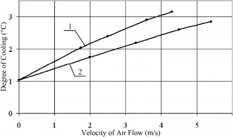
In Figure 9, we present the dependence of water cooling on air velocity under two modes (curve 1 corresponds to cross flow, and curve 2 to counter-flow). Here, data are given for the T20 tray, length L = 1.7 m, water flow rate G = 0.106 kg/s, angle of tray inclination j = 30 deg, initial water temperature tu = 40°С, and air temperature ta = 23°С. Under the action of air flow, the value of Dt, naturally, increases, but depends on the direction of air flow.
Figure 9. Influence of the direction of air flow on the degree of water cooling
Thus, as a result of performed experiments, we found a highly efficient heat-exchange profiled surface (the best of studied), having spherical dimples with a diameter D = 16 mm and a depth h = 5 mm, arranged in chess order at a distance between their centers S = 32 mm [15]. Its heat transfer characteristics are almost three times greater than that for a smooth surface.
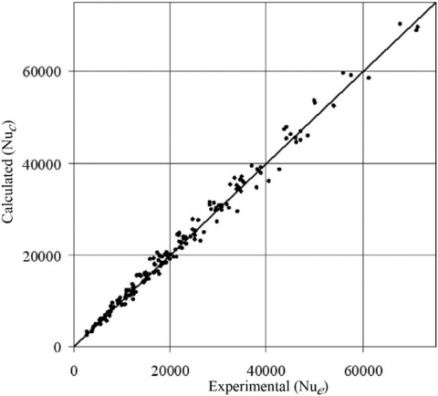
The generalization formula for the mode of air – water cross flow looks like:
$\mathrm{Nu}=7.3 \mathrm{Re}_{f}^{0.03} \mathrm{Re}_{r}^{0.5}(\mathrm{L} / l)^{0.57}$ (3)
in the range 510 £ Ref £ 3180, 26,070 £ Rer £ 1,462,000, 3.2 £ L/l £ 28.3.
Figure 10. Comparison of the experimental Nuе and calculated Nuс numbers
In Figure 10, we compare the experimental and calculated by formula (3) Nusselt numbers. The maximal deviation of experimental points from calculated ones does not exceed 17.3%, and the root mean square deviation is 7.1%. The best surface can be recommended for use in heat exchangers.
(1) Profiling of a solid surface, along which a liquid film flows down, in the form of spherical dimples leads to an unexpectedly high intensification of heat exchange between the film and air over it as compared with the flow along a smooth surface. This is caused by the substantial turbulization of flow and much better mixing of liquid layers in the film.
(2) Under conditions of air – liquid cross flow, the heat exchange between them is much more intense than at their counter flow.
(3) We obtained generalized dependences that enable one to calculate the heat transfer coefficient from water to air in a quiescent environment and in the case of air blowing of the film.
(4) The best heat transfer surface can be recommended for contact heat exchangers of different purposes.
|
c |
specific heat |
|
D |
diameter of spherical dimple |
|
F |
surface area of water film |
|
G |
water flow rate |
|
h |
dimple depth |
|
L |
tray length |
|
l |
tray width |
|
Q |
heat flux between water film and air |
|
S |
distance between the centers of dimples |
|
t |
temperature |
|
V |
velocity |
|
Greek letters |
|
|
α |
heat exchange coefficient from water to air |
|
Δt |
degree of cooling |
|
λ |
thermal conductivity |
|
v |
coefficient of kinematic viscosity |
|
ρ |
density |
|
φ |
angle of tray inclination |
|
Indices |
|
|
a |
air |
|
r |
relative value |
|
s |
smooth surface |
|
u |
upper cross section of tray |
|
w |
water |
[1] Isaev, S.A., Kornev, N.V., Leontiev, A.I., Hassel, E. (2010). Influence of the Reynolds number and the spherical dimple depth on turbulent heat transfer and hydraulic loss in a narrow channel. International Journal of Heat and Mass Transfer, 53(1-3): 178-197. https://doi.org/10.1016/j.ijheatmasstransfer.2009.09.042
[2] Leont’ev, A.I., Olimpiev, V.V. (2011). Thermophysics and heat engineering of the promising heat exchange intensifiers. Izv. Ross. Akad. Nauk, Énergetika, 1: 7-31.
[3] Turnov, J., Kornev, N., Zhdanov, V., Hassel, E. (2012). Flow structures and heat transfer on dimples in a staggered arrangement. International Journal of Heat and Fluid Flow, 35: 168-175. https://doi.org/10.1016/j.ijheatfluidflow.2012.01.002
[4] Xie, G., Liu, J., Ligrani, P.M., Zhang, W. (2013). Numerical analysis of flow structure and heat transfer characteristics in square channels with different internal-protruded dimple geometrics. International Journal of Heat and Mass Transfer, 67: 81-97. https://doi.org/10.1016/j.ijheatmasstransfer.2013.07.094
[5] Liu, J., Song, Y., Xie, G., Sunden, B. (2015). Numerical modeling flow and heat transfer in dimpled cooling channels with secondary hemispherical protrusions. Energy, 79: 1-19. https://doi.org/10.1016/j.energy.2014.05.075
[6] Luo, L., Wang, C., Wang, L., Sunden, B., Wang, S.T. (2016). Heat transfer and friction factor performance in a pin fin wedge duct with different dimple arrangements. Numerical Heat Transfer, Part A, 69(2): 209-226. https://doi.org/10.1080/10407782.2015.1052301
[7] Luo, L., Wang, C., Wang, L., Sunden, B., Wang, S.T. (2016). Heat transfer and friction factor in a dimple-pin fin wedge duct with various dimple depth and converging angle. International Journal of Numerical Methods in Heat and Fluid Flow, 26(6): 1954-1974. https://doi.org/10.1108/HFF-02-2015-0043
[8] Leontiev, A.I., Kiselev, N.A., Burtsev, S.A., Strongin, M.M., Vinogradov, Y.A. (2016). Experimental investigation of heat transfer and drag on surfaces with spherical dimples. Experimental Thermal and Fluid Science, 79: 74-84. https://doi.org/10.1016/j.expthermflusci.2016.06.024
[9] Singh, P., Ekkad, S.V. (2017). Detailed heat transfer measurements of jet impingement on dimpled target surface under rotation. ASME Journal of Thermal Science and Engineering Applications, 10(3): 031006. https://doi.org/10.1115/1.4039054
[10] Luo, L., Yan, H., Du, Wei., Wang, S., Li, Ch. (2019). Flow structure and heat transfer characteristics of a rectangular channel with pin fins and dimples with different shapes. Journal of Thermal Science and Engineering Applications, 11(2): 024501. https://doi.org/10.1115/1.4041598
[11] Dubrovsky, V.V., Podvysotsky, A.M., Shraiber, A.A. (2018). Heat transfer of a liquid film flowing down along a profiled surface with air. Institute of General Energy, National Academy of Sciences of Ukraine, Kiev 77 p. (in Ukrainian). http://www.nas.gov.ua/EN/Book/Pages/default.aspx?BookID=0000011608.
[12] Lykov, A.V. (1972). Heat and mass transfer, Energy, Moscow 560 p. (in Russian). http://urss.ru/cgi-bin/db.pl?lang=Ru&blang=ru&page=Book&id=26348.
[13] Shraiber, A.A., Dubrovsky, V.V., Podvysotsky, A.M. (2010). Generalization of experimental data on heat transfer of a liquid film, flowing down along smooth and profiled surfaces, with air. Promyshlennaya Teplotekhnika, 32 (4): 21-27. Obobshchenie opytnykh danykh po teploobmenu plenki zhidkosti, stekayushchei po gladkim i profilirovanym poverkhnostyam, s vozdukhom. http://dspace.nbuv.gov.ua/handle/123456789/60584
[14] Dubrovsky, V.V., Podvysotsky, A.M. (2014). Heat transfer in film cooling towers with profiled surface of sprinklers under conditions of counter and cross directions of air flow. Problemy Zahal’noi Enerhetyky, 1(36): 55-60. Teploobmin u plivkovykh hradyrmyakh z profil’ovanoyu poverkhneyu zroshuvachiv v umovakh pozdovzhn’oho ta perekhresn’oho napryamku povitrayanoho potoku. http://pge.org.ua/index.php?option=com_docman&task=art_details&mid=20141&gid=14&lang=ua.
[15] Dubrovsky, V.V., Podvysotsky, A.M., Shraiber, A.A. (2019). Method for the intensification of heat transfer between flowing liquid film and surrounding gas, Patent of Ukraine for a utility model No. 130954, State register of patents of Ukraine for utility models, (in Ukrainian). https://base.uipv.org/searchINV/search.php?action=search.