Gokulavani Palaniappan | Muthtamilselvan Murugan* | Qasem M. Al-Mdallal | Bahaaeldin Abdalla | Deog-Hee Doh
© 2020 IIETA. This article is published by IIETA and is licensed under the CC BY 4.0 license (http://creativecommons.org/licenses/by/4.0/).
OPEN ACCESS
This research reports the outcome of a numerical investigation of convection in ventilation square cavities contains parallel insulated baffles. The left and right walls of the cavity are kept at the high temperature. Whereas the top, bottom cavity walls, parallel baffles are adiabatic. The opening slots are positioned at the top, bottom corners of the hot vertical walls. The governing Navier-Stokes equations are formulated in the form of vorticity- stream functions. The finite difference method is used to find the values of the primitive variables. The effects of baffles size (Sb − 0.25, 0.50, 0.75), 3 various positions of the parallel baffle, Rayleigh number (103 − 106), Reynolds number (30, 300, 600) are discussed with the flow fields, isotherms, and Nusselt number. It is found that the behavior of ventilation cavities does not only depend on the size of the baffles and its positions. It highly depends on the configuration of the ventilation cavity too. Further, the flow fields are restricted by the largest baffles size of Sb = 0.75.
heat transfer, ventilation cavity, finite difference method, parallel baffles, convection
Buoyancy induced flow and natural convection of a sealed cavity with protruding object has many industrial applications. Such as microelectronics fabrication, solar collectors, crystal growth, nuclear reactor, radioactive waste containers. The extensive review work is done by Catton [1] and Ostrach [2]. They noticed that the many advantages of the convection in enclosures in their review. Frederick [3] considered an inclined square cavity and a partition fixed at the cold wall for study. He furnished a result that the considerable length of the partition enhances the heat transfer. Natural convection of partially heated below on the rectangular cavity was investigated by Hasnaoui et al. [4]. Kandaswamy et al. [5] conducted a numerical study on the square cavity with a heated plate. They found that the efficient heat transfer happened with the vertical heated plate than the horizontal. Haghighi and Vafai [6] studied the effect of the different aspect ratio of the cavity with partition numerically. They reported that the heat transfer suppressed by the adiabatic vertical partition whereas it is increased by the adiabatic horizontal partition. Convection of square enclosure filled with the nanofluid along with the hot block was studied by Sheremet et al. [7]. Recently, the square cavity contained Al2O3 - water with parallel vertical heaters under magnetic field is numerically analyzed by Solghar [8]. In literature [9-14], the various shape of the enclosure, the protruding object and the different condition on the inside object have been investigated.
Although sealed enclosure is useful in many industrial applications, the uses of ventilation cavity are unavoidable. The ventilation cavity along with the protruding object has a vast application in nature and industries. Such as human respiration, energy conservation in the buildings, ventilation in rooms, material processing, food processing. Shuja et al. [15] examined the mixed convection in an open square cavity along with the protruding solid body of the different aspect ratio. They found that the changes in the exit port location affect the flow field mode. Bhoite et al. [16] investigated a series of heat-producing components in a shallow enclosure. They revealed that the buoyancy effect becomes insufficient beyond Reynolds number 600. The heat-generating rod placed inside an open rectangular enclosure was investigated numerically and experimentally by Radhakrishnan et al. [17]. They have found a good compromise between their numerical and experimental results. Bilgen and Balkaya [18] examined the natural convection of an open cavity contains discrete heaters. In their study, they maintained the open ports at the right vertical wall and used different sizes of vertical fins attached in the left vertical wall. The heat-generating solid blocks in a ventilation square cavity were explored by Shuja et al. [19]. They noted that thermal performance depends on the location of the ports, the conducting body size and orientation. Rahman et al. [20] reported the effects of physical parameters on a solid circular block situated in an open cavity. Their results indicate that the thermal performance, flow field, drag force in the cavity depends on the physical parameters. Kalidasan et al. [21] considered an open square cavity contains a vertical mid partition for their study. They recorded that the heat transfer rate increases with the Reynolds number. Selimefendigil and Oztop [22] studied the convection of ferrofluid in an open square cavity with the adiabatic rotating cylinder. They reported the increasing Reynolds enhances the value of the average Nusselt number. Hussain et al. [23] performed the computational analysis in a horizontal open cannel filled with the hybrid nanofluid having adiabatic square obstacle inside the channel. In their study they focused the performance of the entropy generation. Kalidasan and Rajesh Kanna [24] made their investigation on an open square cavity filled with the hybrid nanofluid, the diagonally placed heaters and an adiabatic square block. They reported that comparatively, the right wall experienced a higher heat transfer rate.
The aforementioned literature survey reveals that sufficient studies have been accomplished on the sealed and ventilation cavity with a single protruding body. Further, the attention is required on the ventilation cavity with multiple protruding objects. Therefore, our present research focuses on the open cavity with multiple baffles. Besides, we concentrate on how the open cavities performance affected by the various sizes, locations of the obstacles and the locations of the opening slots.
Physical model of the current problem is demonstrated in Figure 1 with the open square cavity named as BT. Where the first letter “B” refers to the position of the inlet, the second letter “T” refers to the position of the outlet. Here we considered 4 different types of cavities named as BT, BB, TT, and TB. We vary the position of the inlet, outlet only at vertical left, right wall respectively. Each cavity contains a pair of the parallel vertical/horizontal baffle in it. The vertical walls are maintained at the hot temperature. The horizontal walls and baffles are adiabatic. The width of the openings is fixed as 15% height of the cavity. The height of the vertical hot walls without opening is denoted by h1. The cold fluid enters into the cavity via the inlet then occupies the enclosure. The parallel baffles are disrupted the incoming fluid flow. The cold fluid optimizes the enclosure’s temperature. Finally, exits from the enclosure via the outlet port. The two-dimensional, laminar, incompressible flow is assumed here. The Boussinesq approximation is valid here. The non-dimensional governing equations of the problem are given below.
Figure 1. Schematic diagram of an open square cavity with parallel baffles
Equation of continuity:
$\frac{\partial U}{\partial X}+\frac{\partial V}{\partial Y}=0$ (1)
X-Momentum equation:
$\frac{\partial U}{\partial \tau }+U\frac{\partial U}{\partial X}+V\frac{\partial U}{\partial Y}=-\frac{1}{\rho }\frac{\partial P}{\partial X}+\nu \left( \frac{{{\partial }^{2}}U}{\partial {{X}^{2}}}+\frac{{{\partial }^{2}}U}{\partial {{Y}^{2}}} \right)$ (2)
Y-Momentum equation:
$\begin{align} & \frac{\partial V}{\partial \tau }+U\frac{\partial V}{\partial X}+V\frac{\partial V}{\partial Y}=-\frac{1}{\rho }\frac{\partial P}{\partial Y}+\nu \left( \frac{{{\partial }^{2}}V}{\partial {{X}^{2}}}+\frac{{{\partial }^{2}}V}{\partial {{Y}^{2}}} \right) \\ & \,\,\,\,\,\,\,\,\,\,\,\,\,\,\,\,\,\,\,\,\,\,\,\,\,\,\,\,\,\,\,\,\,\,\,\,\,\,\,\,\,\,\,\,\,\,\,\,\,\,\,\,\,\,\,\,\,\,\,\,\,\,\,\,\,\,\,\,\,+g\beta \left( T-{{T}_{in}} \right) \\\end{align}$ (3)
Energy equation:
$\frac{\partial T}{\partial \tau }+U\frac{\partial T}{\partial X}+V\frac{\partial T}{\partial Y}=\alpha \left( \frac{{{\partial }^{2}}T}{\partial {{X}^{2}}}+\frac{{{\partial }^{2}}T}{\partial {{Y}^{2}}} \right)$ (4)
where, U and V are velocity components in X and Y direction respectively, P and T represents the pressure and temperature. And the fluid properties are density ρ, kinematic viscosity ν, the coefficient of volumetric expansion β and thermal diffusivity α. The gravity g acts downwards normal to the x-axis.
The non-dimensional vorticity-stream function formulation of the Eqns. (1) - (4) can be written as follows:
$\frac{\partial \theta }{\partial t}+u\frac{\partial \theta }{\partial x}+v\frac{\partial \theta }{\partial y}=\frac{1}{Ra\Pr }\left( \frac{{{\partial }^{2}}\theta }{\partial {{x}^{2}}}+\frac{{{\partial }^{2}}\theta }{\partial {{y}^{2}}} \right)$ (5)
$\frac{\partial \omega }{\partial t}+u\frac{\partial \omega }{\partial x}+v\frac{\partial \omega }{\partial y}=\frac{1}{Re}\left( \frac{{{\partial }^{2}}\omega }{\partial {{x}^{2}}}+\frac{{{\partial }^{2}}\omega }{\partial {{y}^{2}}} \right)+\frac{Ra}{PrR{{e}^{2}}}\frac{\partial \theta }{\partial x}$ (6)
$\frac{{{\partial }^{2}}\psi }{\partial {{x}^{2}}}+\frac{{{\partial }^{2}}\psi }{\partial {{y}^{2}}}=-\omega $ (7)
$\omega =\frac{\partial v}{\partial x}+\frac{\partial u}{\partial y}$ (8)
$u=\frac{\partial \psi }{\partial y};\,\,\,\,\,v=-\frac{\partial \psi }{\partial x}$ (9)
The non-dimensional variables occur in the above equations are defined as:
$x=\frac{X}{L},\,\,\,\,\,y=\frac{Y}{L},\,\,\,\,\,u=\frac{U}{{{U}_{in}}},\,\,\,\,\,v=\frac{V}{{{U}_{in}}}$
$t=\frac{{{U}_{in}}}{L}\tau ,\,\,\,\,\,\theta =\frac{T-{{T}_{in}}}{{{T}_{w}}-{{T}_{in}}}\,,\,\,\,\,\psi =\frac{\Psi }{\nu },\,\,\,\,\,\omega =\frac{\zeta }{\left( {\nu }/{{{L}^{2}}}\; \right)}$
And the parameters are Prandtl number $Pr=\frac{\nu }{\alpha }$, Reynolds number $Re=\frac{{{U}_{in}}L}{\nu }$, Rayleigh number $Ra=\frac{g\beta ({{T}_{w}}-{{T}_{in}}){{L}^{3}}}{\nu \alpha }$.
2.1 Boundary conditions
The non-dimensional boundary conditions of the present problem are follows:
$\frac{\partial \theta}{\partial y}=0$ for horizontal; $\frac{\partial \theta}{\partial x}=0$ for vertical
$\theta=1$ for x=0,1; $\frac{\partial \theta}{\partial y}=0$ for y=0,1
${{\omega }_{w}}=-\frac{2\left( {{\psi }_{w+1}}-{{\psi }_{w}} \right)}{{{h}^{2}}}$
where, c1 and c2 are arbitrary constant with c1 − c2 equals to the mass flow rate which enters into the cavity across the opening.
2.2 Heat transfer analysis
In order to estimate the heat transfer rate along the vertical hot walls, it is required to observe the variations of the local Nusselt number on those walls. The local Nusselt number calculated along the cold walls excluding the ventilation ports. They are defined as
$N{{u}_{Left}}={{\left. -\frac{\partial \theta }{\partial x} \right|}_{x=0}}$ (10)
$N{{u}_{Right}}={{\left. -\frac{\partial \theta }{\partial x} \right|}_{x=1}}$ (11)
The comparison of the cooling efficiency between the different configured cavities are measured by the average Nusselt number.
$N{{u}_{avg}}=\frac{1}{2}\int\limits_{0}^{{{h}_{1}}}{\left( N{{u}_{Left}}+N{{u}_{Right}} \right)dy}$ (12)
$N{{u}_{avg}}=\frac{1}{2}\int\limits_{0}^{{{h}_{1}}}{\left( \left( {{\left. -\frac{\partial \theta }{\partial x} \right|}_{x=0}} \right)+\left( {{\left. -\frac{\partial \theta }{\partial x} \right|}_{x=1}} \right) \right)dy}$ (13)
where, h1 denotes the height of the vertical walls without ventilation ports.
The governing non-dimensional partial differential equations along with the boundary conditions are solved numerically by using the finite difference (Wilkes and Churchill [26]). The alternating direction implicit method (Roache [27]) is employed to vorticity transport, energy equation. To solve the stream function the successive over relaxation method (Patankar [28]) is used. The over relaxation parameter value is taken as 1.3. The convergence criteria to obtain a steady-state solution is
$\frac{\left| {{\phi }_{n+1}}(i,j)-{{\phi }_{n}}(i,j) \right|}{\left| {{\phi }_{n+1}}(i,j) \right|}\le {{10}^{-5}}$ (14)
where, ϕ denotes the temperature (θ), vorticity (ω), stream function (ψ) and n represents the time. The time step 10−4 is used in the computation.
3.1 Grid refinement test
The uniform grid system is used for the current computation. The grid test is done with the various grid sizes of 21×21, 41×41, 61×61, 81×81, 101×101 and 121×121. The average Nusselt number on the BT open cavity with the parameters Ra = 105, Re = 300, P2, Sb =0.50 is taken for the test. The test result is shown in Figure 2. From that 81×81 grid system is sufficient for the current study.
Figure 2. Grid independent study
3.2 Code validation
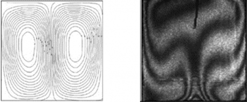
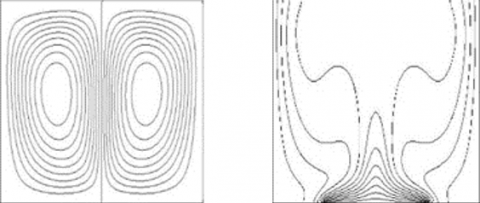
The accuracy of the present computational code is validated against past benchmark results. For that, the differentially heated square cavity filled with air is taken. The comparison made with the value of average Nusselt number on the heated wall. Our present result is compared with the results of De Vahl Davise [29], Barakos et al. [30] and Khanafer et al. [31] and Arefmanesh et al. [32] in Table 1. The good agreement is found with other’s results. Further, one more validation is done against the experimental, numerical results of Corvaro and Paroncini [33]. For this study, we chose an air-filled square cavity with the heated baffle placed at the bottom wall. The obtained results are in satisfactory agreement with their experimental and numerical results (Figure 3).
Experimental Result
Numerical Result
Present Result
Figure 3. Comparison results of Streamlines and Isotherms on a closed cavity with length of 0.5L centrally placed heat source on the cavity bottom wall for Ra=1.3×10⁵
The square ventilation cavities with parallel horizontal/vertical baffles are carried out for the numerical simulation. To optimize the heat transfer inside the cavity, we allowed the cold air to flow into the cavity. The adiabatic baffles also playing an important role in it. So, the study is mainly considered with the size of the baffles (Sb=0.25, 0.50, 0.75), positions of the parallel baffles (P1, P2, P3) in 4 models of the open cavities. The computations are carried out with the various Rayleigh number (103−106), Reynolds numbers (30, 300, 600) and Prandtl number (0.71). The parallel baffles are placed vertically as well as horizontally. The distance between the two adiabatic baffles is fixed as 0.25L. The positions of the baffles are denoted by P1 - bottom left of the open cavity, P2 - a center of the cavity, P3 - top right of the cavity. The position points of the parallel horizontally and vertically placed baffles with Sb =0.50 is given in Table 2. The position points denoted at the center point of the parallel baffles. The computed results are discussed graphically.
Table 1. The comparison result of Nuavg on the air filled closed square cavity
|
|
Ra=103 |
Ra=104 |
Ra=105 |
Ra=106 |
|
De Vahl Davis [29] |
1.118 |
2.243 |
4.519 |
8.719 |
|
Barakos et al. [30] |
1.114 |
2.245 |
4.510 |
8.806 |
|
Khanafer et al. [31] |
1.118 |
2.245 |
4.522 |
8.829 |
|
Arefmanesh et al. [32] |
1.118 |
2.270 |
4.644 |
9.047 |
|
Present study |
1.137 |
2.263 |
4.549 |
8.862 |
Table 2. The position point values
|
Orientation of the parallel baffles |
P1 |
P2 |
P3 |
|
Horizontal |
(0.375,0.25) |
(0.50,0.50) |
(0.625,0.75) |
|
Vertical |
(0.25,0.375) |
(0.50,0.50) |
(0.75,0.625) |
The values of the parameters are Ra = 105, Re = 300, P2, Sb = 0.50, Pr = 0.71 and the distance between the baffles = 0.25. The above said parameters are fixed unless otherwise specified.
4.1 Effects of the horizontal parallel baffles
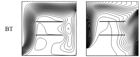
Flow behavior and isotherms of four cases of the open cavity with parallel horizontal baffles can absorb from Figure 4. Close examination of these streamlines and isotherms reveals that the general behavior of the mainstream line flows above the parallel baffles. The isotherms are more packed near the vertical walls. There is no vortex formed near the inlet region because of the immense momentum around that region.
Figure 4. Streamlines and Isotherms for variously configured cavities with horizontal baffles
All the cases except TB, fewer vortexes are formed only below the mainstream. The cold air transfers the heat from left to right. Figure 5 depicts the effects of various sizes of the baffles in the BT ventilation cavity. When we increase the size of the heaters, the number of vortexes also increased. The streamlines are condensed near the left vertical walls. Due to the higher temperature gradients, the isotherms are stronger near the left wall. And it can be seen clearly from the right wall that the slope of the isotherm is increased. This is evident in the improvement of conduction to convection. Hence the augmentation of the convection can achieve in the increasing size of the baffle.
Figure 5. Streamlines (Left) and Isotherms (Right) for BT open cavity with different sizes of the horizontal parallel baffles
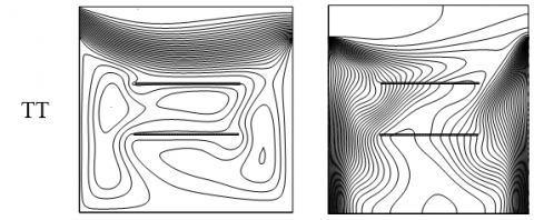
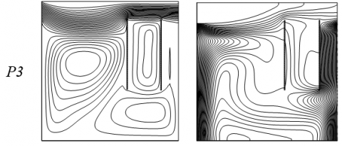
Figure 6. Streamlines (Left) and Isotherms (Right) for TT open cavity with various positions of the horizontal parallel baffles
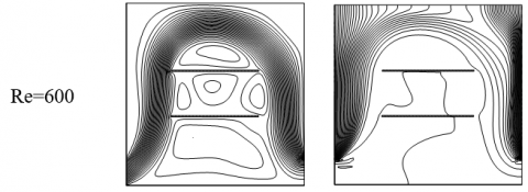
Figure 6 shows the streamlines and isotherms of TT cavity with various positions of the baffles. At the bottom (P1) and centre (P2) positions, the mainstream flows down and gets interacted with the baffles, create a vortex then change its way to the outlet. When the baffles placed at the position of the top (P3), it disturbs the main fluid stream to go out in addition condensed the streamlines right top corner of the cavity. It also creates a clockwise vortex below the baffles and the counter-clockwise vortex in between the baffles, left side of the cavity. The various position of the baffles how affects the thermal field is clearly shown in the isotherms. At P3 position, the baffle blocks the fluid flow significantly. There is a disturbance happened to bring out the inside cavity heat to out. So, the isotherms are steeper above the baffles, near the right wall of the cavity.
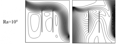
Figure 7. Effect of variable Rayleigh number on the TB configured cavity with horizontal parallel baffles
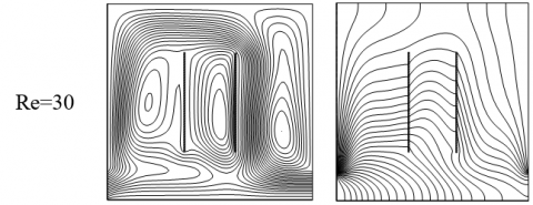
Effects of variable Rayleigh number on TB configured cavity presented in Figure 7. Streamline reveals that when the low buoyancy (Ra <= 104) it forms a counter-clockwise vortex in between the baffles and the clockwise vortex below the baffles. Further, the increase of Ra = 105, the counter-clockwise vortex prolonged to the left wall and flows downwards. When Ra = 106 the buoyancy is further increased. It makes a discernible change in the mainstream flow. The counter-clockwise vortex separated into two intensified vortexes. The concentrated clockwise vortex also appeared above the main flow stream. Due to the lack of convection isotherms are stratified vertically along the hot walls. When Ra increases, due to convection the isotherms are started to move around the cavity. Figure 8 displays the various Reynolds number effects on the BB open cavity. For Re = 10, the main flow bifurcates with one stream flows from inlet to outlet directly along the bottom area of the cavity wall. The other one occupies almost the entire cavity. Further an increase in Re, the flow raises along the vertical hot wall, travels above the baffles then finds its way to out. Some vortexes are formed around the area of the parallel baffle. Whereas, the isotherms are moving top of the cavity and settle along vertical walls.
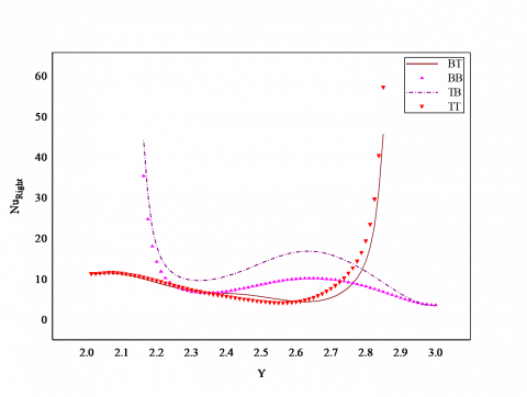
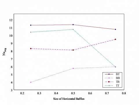
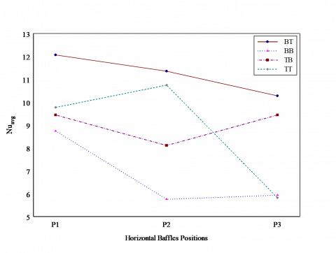
Figure 9 illustrates the variation of local Nusselt number on the four cases of the ventilation cavity. In Figure 9(a), all configured cavities experienced the same amount of heat transfer at the vertical left wall. From Figure 9(b), the transfer of heat in the right heated wall varies significantly in all configured cavities. In general, the adjacent areas near the openings have experienced more heat transfer. Effects of the various sizes of the baffles on the differently configured cavities are demonstrated in Figure 10. Among four configured cavities, the BT cavity produces higher heat transfer rate. The TT and BB cavities are having the same rate of heat transfer with the sizes of the baffles Sb =0.75. The size of the horizontal baffle is directionally proportional to the overall heat transfer rate only on the BB case. How the various position of the baffle changes the heat transfer rate in open cavities is shown in Figure 11. The heat is transferred effectively on the BT configured cavity in all position of the baffle. The overall heat transfer rate is suddenly decreased in the TT case when the position of the baffle changed from the centre to top.
Figure 8. Effect of variable Reynolds number on the BB configured cavity with horizontal parallel baffles
(a) Left wall
(b) Right wall
Figure 9. Local Nusselt number on the vertical walls of the open cavities with horizontal baffles
Figure 10. Effect of various sizes of the horizontal baffles
Figure 11. Effect of various positions of the horizontal baffles
4.2 Effects of the vertical parallel baffles
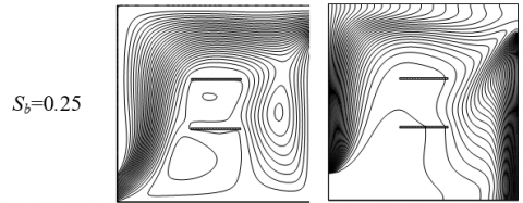
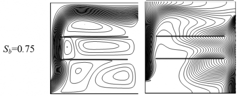
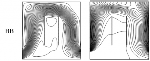
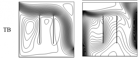
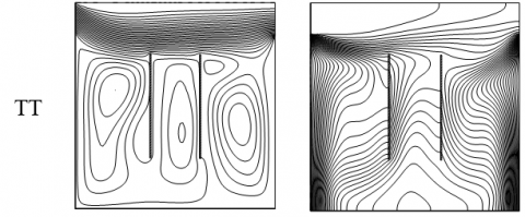
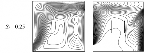
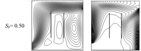
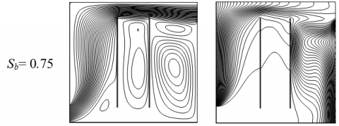
Figure 12 illustrates the effects of vertical parallel plates on the fluid flow and isotherms of the four configured cavities. One can see that in every configuration other than the mainstream the strong or weak vortex has formed. The vortexes are formed below the mainstream. The parallel baffles disturbed the heat transfer of the fluid. The dense isotherms are found near the vertical walls due to higher thermal variation. Figure 13 shows the streamlines, isotherms of BT configured cavity with various size of the vertical parallel baffle. The increase in the size of the baffle compresses the streamlines in the top of the cavity. The clockwise vortex on the right side of the baffle is also detached from the main flow. Basically, heat is transferring from hot walls to the entire area of the cavity. This process is blocked by adiabatic parallel baffles. When the size of the baffles increases, the spreading heat from the left wall is shrinking and the heat from the right touches the right vertical baffle then turns its way out.
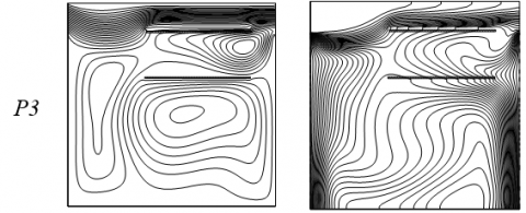
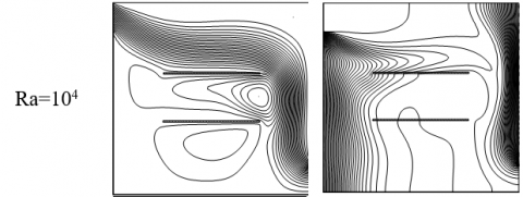
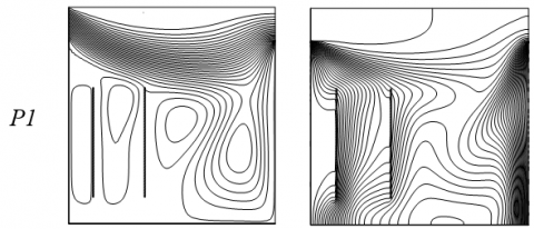
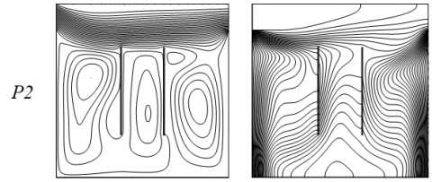
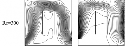
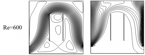
Figure 14 reveals that the position of the baffle affects the fluid behavior of the TT configured cavity. It is a TT configured cavity so, the fluid flows horizontally top of the cavity. Changes in the position of the baffles create a recirculation cell in the remaining area of the cavity. Alter the position form P1 - P3, the isotherms are more parallel along the vertical heated walls. The streamlines, isotherms of the TB open cavity show the effect of the Rayleigh numbers in Figure 15. The number of recirculation cells increases and gets strengthened with the increasing Rayleigh number. Also, the new cell formed in the top right corner of the cavity with Ra >= 105. The vertical thermal stratification along the vertical walls starts distributing the heat in the centre region of the cavity with the increasing Ra. Effect of variable Reynolds number on the BB configured cavity displays in Figure 16. The inflow is not powerful for Re=10. Owing to the inflow stream is divided into two. The strong streams are rising upwards then traveling above the baffles finally turns toward the exit. The weak streams are flowing bottom of the cavity to reach the outlet. For the higher Re, the mainstream goes above the baffle then returns downwards to reach the exit. The horizontal stratified temperature distribution is absorbed for Re=10. Furthermore, the increase in Reynolds number makes more dense-packed isotherms in the vicinity of the vertical walls. The cold air occupies the remaining region of the cavity.
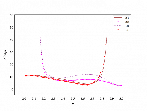
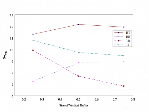
Variation of the local Nusselt number along the vertical walls of the four configured open cavities shown in Figure 17. There is no significant difference in the local Nusselt number of the left wall of all cavities, which is shown in Figure 17(a). From Figure 17(b), the variation of the local Nusselt number along the right wall of each cavity also has same values except the middle region of the right vertical wall. It slightly varies in the interval (2.2 - 2.8). Figure 18 portrays the various size vertical baffles effects on all cases of the open cavity. Size of the baffle is inversely proportional to the Nuavg in TB case. The performance of the TT case also has the same behavior of TB case. Comparatively, the BT cavity has a higher heat transfer rate with the increasing size of the baffle. At Sb =0.25 the BB has the least performance among all. Figure 19 elucidates the effect of various positions of the baffles on open cavities. The BT open cavity performs efficiently at P1, P2. At the position P3, the TB cavity achieves the best heat transfer rate. The TT cavity has a least heat transfer rate at P1, P3.
Figure 12. Streamlines and Isotherms for variously configured cavities with vertical baffles
Figure 13. Streamlines (Left) and Isotherms (Right) for BT open cavity with different sizes of the vertical parallel baffles
Figure 14. Streamlines (Left) and Isotherms (Right) for TT open cavity with various positions of the vertical parallel baffles
Figure 15. Effect of variable Rayleigh number on the TB configured cavity with vertical baffles
Figure 16. Effect of variable Reynolds number on the BB configured cavity with vertical parallel baffles
(a) Left wall
(b) Right wall
Figure 17. Local Nusselt number on the vertical walls of the open cavities with vertical baffles
Figure 18. Effect of various sizes of the vertical baffles
Figure 19. Effect of various positions of the vertical baffles
The numerical simulation carried out to optimize the thermal effects in the cooling equipment of the open square cavity contains an adiabatic parallel vertical/horizontal baffles.
The air is used as a coolant inside the cavity. Further, the study is concentrated on the size of the parallel baffles and is locations. Depending on the current investigation the following results are concluded.
(1) The increase in the size of the baffles and its variable positions deliver a great impact on the performance of the open cavities. However, it also depends on the configuration of the cavity.
(2) When we are considering the special case no remarkable divergence for the horizontal or vertical baffle.
(3) For the case of BT open cavity produces an outstanding heat transfer performance.
(4) It is found that the heat transfer rate is decreased when the vertical baffle size is increases.
(5) The alternating position of the horizontal parallel baffle the BT case yields favorable results.
(6) The heat transfer effect is nonlinear for an effect of various positions of the vertical baffles.
Authors would like to acknowledge and express their gratitude to the United Arab Emirates University, Al Ain, UAE for providing the financial support with grant No. 31S363-UPAR(4) 2018.
|
g |
gravitational acceleration m. s-2 |
|
H |
height of the cavity, m |
|
h1 L |
height of the hot wall without opening, m length of the cavity, m |
|
Nu |
Nusselt number |
|
P |
pressure, N. m-2 |
|
Pr |
Prandtl number |
|
P1,2,3 |
Positions of the baffles |
|
Ra |
Rayleigh number |
|
Re |
Reynolds number |
|
Sb |
Size of the parallel baffle |
|
t |
dimensionless time |
|
T |
temperature, K |
|
U,V |
dimensional velocity components, m. s-1 |
|
u,v |
dimensionless velocity components |
|
X,Y |
dimensional coordinates |
|
x,y |
dimensionless coordinates |
|
Greek symbols |
|
|
$\alpha$ |
thermal diffusivity, m2. s-1 |
|
$\beta$ |
thermal expansion coefficient, K-1 |
|
ν |
kinematic viscosity, m2. s-1 |
|
ω |
dimensionless vorticity |
|
$\Psi$ |
dimensional stream function, m2. s-1 |
|
ψ |
dimensionless stream function |
|
ρ |
density, kg. m-3 |
|
τ |
time, s |
|
θ |
dimensionless temperature |
|
ζ |
dimensional vorticity, s-1 |
|
Subscripts |
|
|
avg |
average |
|
in |
inflow |
|
w |
condition at wall |
[1] Catton, I. (1979). Natural convection in enclosures. Proceedings, 6th International Heat Transfer Conference Toronto, Canada, 6: 13-43. http://dx.doi.org/10.1615/IHTC6.2350
[2] Ostrach, S. (1988). Natural convection in enclosures. Journal of Heat Transfer, 110(4b): 1175-1190. http://dx.doi.org/10.1115/1.3250619
[3] Frederick, R.L. (1989). Natural convection in an inclined square enclosure with a partition attached to its cold wall. International Journal Heat and Mass Transfer, 32(1): 87-94. http://dx.doi.org/10.1016/0017-9310(89)90093-8
[4] Hasnaoui, M., Bilgen, E., Vasseur, P. (1992). Natural convection heat transfer in rectangular cavities partially heated from below. Journal of Thermophysics and Heat Transfer, 6(2): 255-264. http://dx.doi.org/10.2514/3.353
[5] Kandaswamy, P., Lee, J., Abdul Hakeem, A.K. (2007). Natural convection in a square cavity in the presence of heated plate. Nonlinear Analysis: Modelling and Control, 12(2): 203-212. http://dx.doi.org/10.15388/NA.2007.12.2.14711
[6] Haghighi, A., Vafai, K. (2014). Optimal positioning of strips for heat transfer reduction within an enclosure. Numerical Heat Transfer, Part A, 66(1): 17-40. http://dx.doi.org/10.1080/10407782.2013.869081
[7] Sheremet, M.A., Oztop, H.F., Pop, I., Abu-Hamdeh, N. (2015). Analysis of entropy generation in natural convection of nanofluid inside a square cavity having hot solid block: Tiwari and das model. Entropy, 18(1): 1-15. http://dx.doi.org/10.3390/e18010009
[8] Solghar, A.A. (2018). Buoyancy convection in a square cavity with parallel heaters under magnetic field. Iranian Journal of Science and Technology, Transactions of Mechanical Engineering, 42: 329-339. http://dx.doi.org/10.1007/s40997-017-0100-6
[9] Oh, J.Y., Ha, M.Y., Kim, K.C. (1997). Numerical study of heat transfer and flow of natural convection in an enclosure with a heat generating conducting body. Numerical Heat Transfer, Part A, 31(3): 289-303. http://dx.doi.org/10.1080/10407789708914038
[10] Ghalambaz, M., Jamesahar, E., Ismael, M.A., Chamkha, A.J. (2017). Fluid-structure interaction study of natural convection heat transfer over a flexible oscillating fin in a square cavity. International Journal of Thermal Sciences, 111: 256-273. http://dx.doi.org/10.1016/j.ijthermalsci.2016.09.001
[11] Aghaei, A., Sheikhzadeh, G.A., Goodarzi, M., Hasani, H., Damirchi, H., Afrand, M. (2018). Effect of horizontal and vertical elliptic baffles inside an enclosure on the mixed convection of a MWCNT’s - water nanofluid and its entropy generation. The European Physical Journal Plus, 133: 486-497. http://dx.doi.org/10.1140/epjp/i2018-12278-4
[12] Wang, L., Zhao, Y., Yang, B., Chai, Z. (2019). A lattice Boltzmann analysis of the conjugate natural convection in a square enclosure with a circular cylinder. Applied Mathematical Modelling, 71: 31-46. http://dx.doi.org/10.1016/j.apm.2019.02.012
[13] Fayz-Al-Asad, M., Sarker, M.M.A., Munshi, M.J.H. (2019). Numerical investigation of natural convection flow in a hexagonal enclosure having vertical fin. Journal of Scientific Research, 11(2): 173-183. http://dx.doi.org/10.3329/jsr.v11i2.38797
[14] Ghachem, K., Hassen, W., Maatki, C., Kolsi, L., Al-Rashed, A.A.A.A., Borjini, M.N. (2018). Numerical simulation of 3D natural convection and entropy generation in a cubic cavity equipped with an adiabatic baffle. International Journal of Heat and Technology, 36(3): 1047-1054. http://dx.doi.org/10.18280/ijht.360335
[15] Shuja, S.Z., Yilbas, B.S., Iqbal, M.O. (2000). Mixed convection in a square cavity due to heat generating rectangular body. International Journal of Numerical Methods for Heat and Fluid Flow, 10(8): 824-841. http://dx.doi.org/10.1108/09615530010359120
[16] Bhoite, M.T., Narasimham, G.S.V.L., Krishna Murthy, M.V. (2005). Mixed convection in a shallow enclosure with a series of heat generating components. International Journal of Thermal Sciences, 44(2): 121-135. http://dx.doi.org/10.1016/j.ijthermalsci.2004.07.003
[17] Radhakrishnan, T.V., Verma, A.K., Balaji, C., Venkateshan, S.P. (2007). An experimental and numerical investigation of mixed convection from a heat generating element in a ventilated cavity. Experimental Thermal and Fluid Science, 32(2): 502-520. http://dx.doi.org/10.1016/j.expthermflusci.2007.06.001
[18] Bilgen, E., Balkaya, A. (2008). Natural convection on discrete heaters in a square enclosure with ventilation ports. International Journal of Heat and Fluid Flow, 29(4): 1182-1189. http://dx.doi.org/10.1016/j.ijheatfluidflow.2008.01.013
[19] Shuja, S.Z., Yilbas, B.S., Khan, S.M.A. (2009). Flow over solid blocks in open ended cavity. Journal of Numerical Methods for Heat and Fluid Flow, 19(5): 633-649. http://dx.doi.org/10.1108/09615530910963562
[20] Rahman, M.M., Parvin, S., Rahim, N.A., Islam, M.R., Saidur, R., Hasanuzzaman, M. (2012). Effects of Reynolds and Prandtl number on mixed convection in a ventilated cavity with a heat-generating solid circular block. Applied Mathematical Modelling, 36(5): 2056-2066. http://dx.doi.org/10.1016/j.apm.2011.08.014
[21] Kalidasan, K., Velkennedy, R., Rajesh Kanna, P. (2014). Numerical investigation on natural convection inside the side ventilated square enclosure with vertical mid-partition. Numerical Heat Transfer, Part A, 66(2): 139-1418. http://dx.doi.org/10.1080/10407782.2014.915695
[22] Selimefendigil, F., Oztop, H.F. (2014). Forced convection of ferrofluids in a vented cavity with a rotating cylinder. International Journal of Thermal Sciences, 86: 258-275. http://dx.doi.org/10.1016/j.ijthermalsci.2014.07.007
[23] Hussain, S., Ahmed, S.E., Akbar, T. (2017). Entropy generation analysis in MHD mixed convection of hybrid nanofluid in an open cavity with a horizontal channel containing an adiabatic obstacle. International Journal of Heat and Mass Transfer, 114: 1054-1066. http://dx.doi.org/10.1016/j.ijheatmasstransfer.2017.06.135
[24] Kalidasan, K., Rajesh Kanna, P. (2017). Natural convection on an open square cavity containing diagonally placed heaters and adiabatic square block and filled with hybrid nanofluid of Nanodiamond - Cobalt oxide/water. International Communications in Heat and Mass Transfer, 81: 64-71. http://dx.doi.org/10.1016/j.icheatmasstransfer.2016.12.005
[25] Kanna, P.R., Das, M.K. (2005). A short note on the entrainment and exit boundary conditions. International Journal for Numerical Methods in Fluids, 50(8): 973-985. http://dx.doi.org/10.1002/fld.1095
[26] Wilkes, J.O., Churchill, S.W. (1966). The finite-difference computation of natural convection in a rectangular enclosure. American Institute of Chemical Engineers, 12(1): 161-166. http://dx.doi.org/10.1002/aic.690120129
[27] Roache, P.J. (1982). Computational Fluid Dynamics, Hermosa, Albuquerque, NM.
[28] Patankar, S.V. (1980). Numerical Heat Transfer and Fluid Flow. Hemisphere, Washington, DC.
[29] De vahl davis, G. (1983). Natural convection of air in a square cavity a bench mark numerical solution. International Journal for Numerical Methods in Fluids, 3(3): 249-264. http://dx.doi.org/10.1002/fld.1650030305
[30] Barakos, G., Mitsoulis, E., Assimacopoulos, D. (1994). Natural convection flow in a square cavity revisited: Laminar and turbulent models with wall functions. International Journal for Numerical Methods in Fluids, 18(7): 695-719. http://dx.doi.org/10.1002/fld.1650180705
[31] Khanafer, K., Vafai, K., Lightstone, M. (2003). Buoyancy-driven heat transfer enhancement in a two-dimensional enclosure utilizing nanofluids. International Journal Heat and Mass Transfer, 46(19): 3639-3653. http://dx.doi.org/10.1016/S0017-9310(03)00156-X
[32] Arefmanesh, M., Najafi, M., Musavi, S.H. (2013). Buoyancy-driven fluid flow and heat transfer in a square cavity with a wavy baffle-meshless numerical analysis. Engineering Analysis with Boundary Elements, 37(2): 366-382. http://dx.doi.org/10.1016/j.enganabound.2012.11.004
[33] Corvaro, F., Paroncini, M. (2007). Experimental analysis of natural convection in square cavities heated from below with 2D-PIV and holographic interferometry techniques. Experimental Thermal and Fluid Science, 31(7): 721-739. http://dx.doi.org/10.1016/j.expthermflusci.2006.07.006