Jasem M. Alhumoud* | Nourah Almashan
© 2020 IIETA. This article is published by IIETA and is licensed under the CC BY 4.0 license (http://creativecommons.org/licenses/by/4.0/).
OPEN ACCESS
In the present analysis, a new geometry of obstacles is considered in order to demonstrate its importance in improving the thermal-hydrodynamic performance of hydrogen fluid within a 2D, rectangular section channel subject to a constant surface temperature condition along its hot top wall. The new obstacle has a variable-position square-shaped gap (called: perforated obstacle), to reduce its resistance to the fluid flow, to decrease the skin friction, in order to determine the optimum configuration for a high heat transfer. This gap has three different positions (dg) in the (h) height baffle section, i.e., dg = 0.25h, 0.5h and 0.75h reported, respectively, as A, B and C types. The governing equations among the fluid and solid sections are determined and solved via the finite volume method (FVM). The obtained results are presented for Re = 5 × 10³ - 2 × 10⁴. The thermal improvement factors of the channel containing the perforated baffle appear to be greater than unity for all dg gap positions situated between 1.143 and 4.236, and dependent on the values of dg and Re, which suggest a better thermo-hydrodynamic performance compared to that obtained with a smooth channel. It is found that the thermo-hydrodynamic improvement value in case C of a 0.75h perforated baffle decreases by 2.747% compared to the case of a simple obstacle with no gap, at Re = 2 × 10⁴. However, the value of this same factor increases by 5.901% and 2.794% when the value of dg is equal to 0.25h and 0.5h, respectively, for this same great value of the Reynolds number. Therefore, the perforated baffle model with a small gap position distance (dg = 0.25h) can be selected as the best geometric model for a good thermal improvement with minimal frictions inside the channel. The subject is relevant and important for industrial applications.
hydrodynamic fluid flow, turbulent flow, rectangular channel, perforated baffle, obstacle with gap, numerical simulation
The study of improving the thermal performance of channels and ducts is one of the most important points of many researches, especially in the field of solar energy. These research works are mainly based on the introduction of ribs, baffles and fins to increase the fluid disturbance leading to the creation of large recycling areas with significant thermal exchanges. Here, a bibliographical analysis is conducted covering various experimental and numerical investigations on convective laminar/turbulent flows in complex geometries that are directly related to the present work. Sahin et al. [1] used the Taguchi experimental design method to investigate effects of some geometry parameters, i.e. the baffle width, length, height, inclination angle, and the corner angle on the friction and convective transfer characteristics inside a heat sink provided by trapezoidal-shaped baffles. Chang et al. [2] focused their experimental analysis to improve the heat transfer characteristics of systems such as radiators, heat exchangers and solar air channels. Chen et al. [3] studied the acoustic impedance of perforated-type plates with a bias-type flow by using a 3D CFD approach. Zhang et al. [4] proposed a model for calculating the mean residence time of particles of different sizes. Their model predictions were compared with measured compositions of different particles. Zhang et al. [5] also used experimental techniques to study the performance of transfer of heat with the characteristics of frictions inside a thermal exchanger employing helical type fins with turbulators. Eiamsa-ard et al. [6] reported a simulation of a convective and laminar flow through a duct with obstacles in their triangular wavy models. Eiamsa-ard et al. [7] studied the transfer of heat of a laminar regime flow in a tube with deflectors of triangular wavy form using a 3D numerical simulation. Boukhadia et al. [8] investigated the performance of rectangular and perforated wings inside a heat exchanger of plate-fin type. Chamoli [9] applied an effective procedure combining RSM and ANN to improve the transfer of heat in a duct with a perforated type obstacle of V-down geometry. Chamoli [10] also proposed a methodology to assess the advantage a perforated section deflector of V-down shape inside a duct. Tan et al. [11] studied the transfer of heat and the flow friction of nanofluids inside a heat exchanger fitted with helical shape baffles and attached fin tubes. Using the Taguchi design of experiment method, Chamoli [12] also reported the best situation of a tube fitted with pore baffles. Cho et al. [13] reported analytical data for a tank with rectangular geometry and obstacles of porous type. A general design equation for perforated-type baffles was formulated by Choi et al. [14].
Chu et al. [15] addressed the situation of a tank at water with various deflectors on the lower wall. Wang et al. [16] showed the enhancement of transfer of heat using the oil-water fluid in exchangers of heat with helical geometry deflectors. Karwa et al. [17] used various deflectors, i.e., with/without pores, to augment the transfer of heat in channels. Mellal et al. [18] used various situations of deflectors to increase the transfer of heat in a heat exchanger. Kumar and Sinhamahapatra [19] analyzed the dynamic effects of single-opening slotted type baffles. Kuzniatsova and Shimanovsky [20] illustrated the geometry of perforated-type baffles to provide minimal equivalent stresses and maximal liquid oscillations damping in a tank reservoir. Zhang et al. [21] reported a heat and fluid characteristic comparison between heat exchangers with various deflectors, i.e. helical, and segmental. You et al. [22] used flower geometry deflectors inside exchangers of heat to study the aspects of transfer of heat and the flow of fluid basing on a numerical simulation with an experimental verification. Mana et al. [23] employed a two-dimensional wave number domain method to study the efficiency of the radiation for a panel of perforated section set in a solid-type deflector. Nanan et al. [24] investigated numerically as well as experimentally heat transfer aspect in a duct with different types of twisted baffle turbulators. Sahel et al. [25] reported a novel deflector in its perforated geometry to enhance the transfer of heat in a duct. Xiao et al. [26] used various types of the fluids and different geometries of the helical model deflector to improve the transfer of heat in a heat exchanger. Saravanakumar et al. [27] reported a model for assessing and evaluating a heater with a finned and baffled wall absorber. Using the method of Taguchi, Du et al. [28] studied and optimized exchangers of heat with deflectors of helical type configuration. Xue et al. [29] studied experimentally the sloshing pressure effects on the tank wall as well as the baffle for various vertical-type baffle configurations and different frequencies.
In this paper, a new model of fins and baffles is studies in order to demonstrate its importance in improving the thermo-hydrodynamic performance of a hydrogen fluid within a two-dimensional, rectangular channel, subject to a constant surface temperature condition along its hot top wall. The new obstacle has a variable-position gap, to reduce its resistance to the flow, to decrease the skin friction, in order to determine the optimum configuration for a high heat transfer. In this study, we will use the method of finite volumes by using a CFD technique. The results will be included in the form of fields such as streamlines, dynamic pressure, mean, axial and transverse velocities, and isotherms, as well as, in the form of profiles such as rate of transfer of heat, ratio of fiction, and thermal enhancement factor, in a. specific Reynolds range, i.e., Re = 5 × 10³ - 2 × 10⁴.
The objective of this present analysis is to conduct a numerical study on turbulent flow and heat transfer of hydrogen fluid in 2D channels of rectangular sections fitted with flat rectangular-type baffles placed on their upper hot and lower insulated walls in a periodically-staggered way as shown in Figure 1. All concerned geometry dimensions [30], i.e., the channel length (L), height (H), inlet section (Linl) and exit section (Lout), and the baffle height (h), thickness (e) and separation distance (Pi), and the considered boundary conditions, i.e., inlet, outlet, hot upper and insulated lower walls are also shown in Figure 1. Two different models of baffles are considered in this study and are inserted into the channel to force recycling cells to improve the flow mixing, and consequently, the amount of heat transfer. In the first situation, a flat baffle without gap (or simple obstacle) was considered (see Figure 1a), and in the second situation, a flat baffle with a square gap (or perforated baffle) was considered (see Figure 1a-d). This gap has three different positions (dg) in the baffle section, i.e., dg = 0.25h, 0.5h and 0.75h referred as cases A, B and C, as shown in Figure 1b, c and d, respectively.
In this study, the following assumptions are made:
The equations governing the fluid flow and heat transfer situation under consideration can be written in the common form as:
$\frac{\partial}{\partial x}(\rho u \phi)+\frac{\partial}{\partial y}(\rho v \phi)=\frac{\partial}{\partial x}\left[\Gamma_{\phi} \frac{\partial \phi}{\partial x}\right]+\frac{\partial}{\partial y}\left[\Gamma_{\phi} \frac{\partial \phi}{\partial y}\right]+S_{\phi}$ (1)
with:
$\phi \equiv(u, v, k, \varepsilon \text { and } \mathrm{T})$
where,
$\phi$ : general variable;
u: x-velocity;
v: y-velocity;
k: turbulent kinetic energy;
ε: turbulent dissipation rate;
$\Gamma_{\phi}$: turbulent diffusion coefficient ; and
$S_{\phi}$: Source term.
Expressions of ϕ, Γϕ and Sϕ:
Fluid mass conservation:
$\phi=1$ (2)
$\Gamma_{\phi}=0$ (3)
$S_{\phi}=0$ (4)
X-direction fluid momentum conservation:
$\phi=u$ (5)
$\Gamma_{\phi}=\mu_{e}$ (6)
$S_{\phi}=-\frac{\partial p}{\partial x}+\frac{\partial}{\partial x}\left[\mu_{e}\left(\frac{\partial u}{\partial x}\right)\right]+\frac{\partial}{\partial y}\left[\mu_{e}\left(\frac{\partial v}{\partial x}\right)\right]$ (7)
Y-direction fluid momentum conservation:
$\phi=v$ (8)
$\Gamma_{\phi}=\mu_{e}$ (9)
$S_{\phi}=-\frac{\partial p}{\partial y}+\frac{\partial}{\partial x}\left[\mu_{e}\left(\frac{\partial u}{\partial y}\right)\right]+\frac{\partial}{\partial y}\left[\mu_{e}\left(\frac{\partial v}{\partial y}\right)\right]$ (10)
Fluid energy conservation:
$\phi=T$ (11)
$\Gamma_{\phi}=\frac{\mu_{e}}{\sigma_{T}}$ (12)
$S_{\phi}=0$ (13)
Kinetic energy of turbulence:
$\phi=\mathrm{k}$ (14)
$\Gamma_{\phi}=\mu_{\ell}+\frac{\mu_{t}}{\sigma_{k}}$ (15)
$S_{\phi}=-\rho \cdot \varepsilon+G$ (16)
Rate of dissipation of turbulence:
$\phi=\varepsilon$ (17)
$\Gamma_{\phi}=\mu_{\ell}+\frac{\mu_{t}}{\sigma_{k}}$ (18)
$S_{\phi}=\left(C_{1 \varepsilon} f_{1} G-C_{2 \varepsilon} f_{2} \rho . \varepsilon\right) \frac{\varepsilon}{k}$ (19)
where,
$\mu_{e}=\mu_{\ell}+\mu_{t}$ (20)
$\mu_{t}=f_{\mu} \rho \cdot C_{\mu} \frac{k^{2}}{\varepsilon}$ (21)
$G=\mu_{t}\left\{2 \cdot\left(\frac{\partial u}{\partial x}\right)^{2}+2\left(\frac{\partial v}{\partial y}\right)^{2}+\left(\frac{\partial v}{\partial x}+\frac{\partial u}{\partial y}\right)^{2}\right\}$ (22)
with:
$\mathrm{C}_{1 \varepsilon}=\mathrm{C}_{3 \varepsilon}=1.44, \mathrm{C}_{2 \varepsilon}=1.92, \mathrm{C}_{\mu}=0.09, \sigma_{\mathrm{k}}=1.0, \sigma_{\varepsilon}=$ $1.3,$ and $\sigma_{\mathrm{T}}=0.85$ (23)
representing the k-epsilon (k-ε) model constant values, reported by Launder and Spalding [31]. The current boundary conditions are presented as:
For the channel inlet section (at x = 0):
$u=U_{i n}$ (24)
$v=0$ (25)
$T=T_{i n}=300 K$ (26)
$\mathrm{k}_{\mathrm{in}}=0.005 U_{i n}^{2}$ (27)
$\varepsilon_{i n}=0.1 k_{i n}^{2}$ (28)
For the channel walls:
$u=v=0$ (29)
$k=\varepsilon=0$ (30)
$T=T_{w}=375 K$ (31)
$\frac{\partial T}{\partial y}=0$ (32)
For the fluid/solid interface:
$T_{f}=T_{s}$ (33)
$\lambda_{f} \frac{\partial T_{f}}{\partial n}=\lambda_{s} \frac{\partial T_{s}}{\partial n}$ (34)
For the channel exit section (at x = L):
$P=P_{a t m}$ (35)
$\frac{\partial \phi}{\partial y}=0$ (36)
The governing parameters are:
Reynolds number:
$\mathrm{Re}=\rho \bar{U} D_{h} / \mu$ (37)
where, Dh is the hydraulic diameter calculated as:
$D_{h}=2 H W /(H+W)$ (38)
Skin friction coefficient:
$C f=\frac{\tau_{w}}{\frac{1}{2} \rho \bar{U}^{2}}$ (39)
Friction factor:
$f=\frac{(\Delta P / L) D_{h}}{\frac{1}{2} \rho \bar{U}^{2}}$ (40)
Local Nusselt number:
$N u_{x}=h_{x} D_{h} / \lambda_{f}$ (41)
The average Nusselt number:
$\overline{N u}=\frac{1}{L} \int_{0}^{L} N u_{x} \partial x$ (42)
The thermal enhancement factor:
$T E F=\left(N u / N u_{0}\right) /\left(f / f_{0}\right)^{1 / 3}$ (43)
Dittus and Boelter correlation (Dittus and Boelter [32]):
$N u_{0}=0.023 \mathrm{Re}^{0.8} \mathrm{Pr}^{0.4}$ for $\operatorname{Re} \geq 10^{4}$ (44)
Petukhov correlation (Petukhov [33]):
$f_{0}=(0.79 \ln \mathrm{Re}-1.64)^{-2}$ for $3 \times 10^{3} \leq \mathrm{Re} \leq 5 \times 10^{6}$ (45)
where, $\mathcal{L}_{w}$ is the wall shear stress, $\bar{U}$ is the average axial velocity of the section, $\Delta P$ is the pressure drop, $N u_{0}$ is the average Nusselt number for a smooth channel, $f_{0}$ is the friction factor for a smooth channel, and $h_{x}$ is the local convective heat transfer coefficient.
Figure 1. Baffled channels without or with gaps under simulation: (a) baffled channel without gaps (simple baffles); baffled channels with gaps (perforated baffles or discrete baffles) of different stations: (b) 0.25×h (or case A, (c) 0.5×h (or case B) and (d) 0.75×h (or case C)
The numerical model is validated successfully by comparisons with previously published studies (see Figures 2 and 3).
Figure 2. Validation of u profiles with [30], under similar conditions, i.e., channel with simple baffles, air fluid, Uin = 7.8 m/s for Re = 8.73 × 10⁴
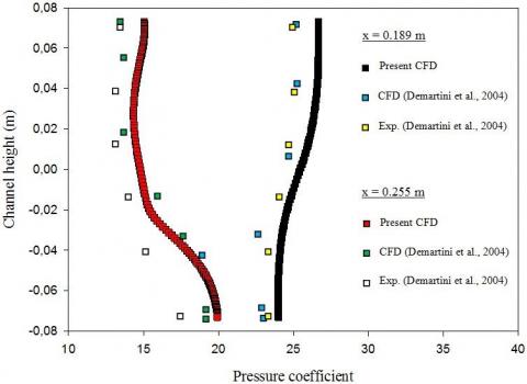
Figure 3. Validation plots of pressure coefficient profiles with reported data [30], under similar conditions, i.e., channel with simple baffles, air fluid, Uin = 7.8 m/s for Re = 8.73 × 10⁴
In order to study the influence of the turbulence model on the numerical solution, a comparison is conducted of four different models of turbulence, i.e., standard k-ε model, RNG k-ε model, standard k-ω model, and SST k-ω model. These turbulence models are also compared with the experimental results of Demartini et al. [30]. The comparison of the results is done under the following conditions: same channel as shown in more details in Demartini et al. [30] (rectangular channel with two rectangular baffle plates without gap in a staggered arrangement), same type of fluid (air); and same inlet velocity (Uin = 7.8 m/s for Re = 8.73 × 10⁴). The comparison results are shown in Figure 4 in terms of the axial velocity profiles along the cross-site located close to the channel outlet at x = 0.525 m. As shown in Figure 4, the standard k-ε first turbulence model is the closest to the experimental model presented by Demartini et al. [30]. Thus, the turbulence model used is the standard k-ε model.
Figure 4. Impact of turbulence model on the u velocity profiles under the following condition: channel with simple baffles, air fluid, Uin = 7.8 m/s for Re = 8.73 × 10⁴
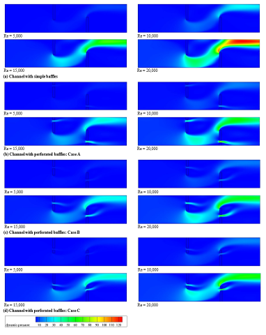
Figure 5 represents the dynamic pressure versus the Re number (from 5,000 to 20,000) for a channel with various lower and upper wall-attached baffle configurations. The dynamic pressure values are variable, depending on the region of the channel. The hydrogen current has high pressure values on the sides of the baffles, exactly on their front sharp edges. The hydrogen current flows at high pressure between the baffle tip and the upper and lower channel surfaces. Maximum pressure values are located near the hot wall, behind the insulated lower surface-attached second baffle, to the channel outlet. The low values of the dynamic pressure are found on the right sides of the baffles and in the dead areas on their left sides. This is for the first situation in the presence of simple baffle and the absence of gapes (see Figure 5a). In other situations, as presented in Figure 5b, c and d, dynamic pressure values decrease due to perforated baffles, compared to simple obstacles. The presence of gaps across the baffles results in the formation of secondary streams flowing through these holes at high pressure. The effect of Re numbers on the dynamic pressure values is also analyzed. The pressure values rise when the number of Reynolds increases, and in all studied cases. The dynamic pressure reaches its maximum value on the back area of the bottom baffle in the hot section of the channel, especially in the absence of gaps (see Figure 5a).
Figure 6 illustrates streamlines for various obstacle geometries at different Re values. It is very clear that the hydrogen current flows steadily, according to regular and parallel lines, from the entrance of the channel, and in all cases proposed. These lines are disturbed after the channel inlet as the current approaches the first baffle located at the channel top region. As expected, the flow deviates from the hot upper region of the channel towards its thermally insulated bottom region, creating a dead zone on the front side of the top baffle near its base. The current is also separated from the solid area of the same obstacle on its front sharp edge. Here, the current is divided into two branches, a main stream that flows forward towards the second obstacle, and a reverse current on the back of the first baffle. As expected, the flow of the hydrogen in the opposite direction results in the formation of cells of recirculation on the right side of the top obstacle, due to a decrease in values of the pressure in this region as reported in Figure 5. These cells are large volume rings, in contact with the right side of the first baffle, as well as with the hot wall of the channel, but away from the left side of the second baffle. The height of these cells of recirculation is approximately the same as the height of the baffle, while its extension reaches the upper limit of the second gap located above the second obstacle. The presence of the lower second baffle also causes a disturbance to the current with a depression on its left side, while the pressure rises across the gap adjacent to its upper face. The front sharp edge of this obstacle presents a point of separation. Here, the hydrogen current flow detaches, which creates a strong cell for recycling on its right side, as a result of a depression in this region. This cell of recirculation has opposite currents with large rotation rings, reaching the end the channel. This is for the first situation in the case of simple baffles as illustrated in Figure 6a. The introduction of perforated baffles helps to activate the dead areas on their frontal sides near their bases as well as to eliminate the weak heat transfer recycling cells on the back sides, thus, a good hydrogen current flow across the entire channel. Furthermore, the position of these holes through these baffles shows a strong effect on the hydrogen current field cells. The presence of the gap in the bottom part of the baffle, near its base, and as shown in the A first case, from Figure 6b, creates secondary currents crossing the recycling areas, next to the inner channel surfaces. The presence of the gap in the center of the baffle leads to the division of the recycling area into two recirculation cells traversed by the secondary current that passes through this gap (B case in Figure 6c. The flow field through the gap existing in the upper part of the baffle (C case in Figure 6d) contributes to the destabilization and elimination of adjacent recycling cells. In general, the strength and size of the recycling cells enhances with the augmentation in the Reynolds number, especially on the back region of the upper baffle and in the absence of gaps.
Current in the opposite direction results in the formation of cells of recirculations on the right side of the top obstacle, due to a decrease in values of the pressure in this region as reported in Figure 5. These cells are large volume rings, in contact with the right side of the first baffle, as well as with the hot wall of the channel, but away from the left side of the second baffle. The height of these cells of recirculation is approximately the same as the height of the baffle, while its extension reaches the upper limit of the second gap located above the second obstacle. The presence of the lower second baffle also causes a disturbance to the current with a depression on its left side, while the pressure rises across the gap adjacent to its upper face. The front sharp edge of this obstacle presents a point of separation. Here, the hydrogen current flow detaches, which creates a strong cell for recycling on its right side, as a result of a depression in this region. This cell of recirculation has opposite currents with large rotation rings, reaching the end the channel. This is for the first situation in the case of simple baffles as illustrated in Figure 6a. The introduction of perforated baffles helps to activate the dead areas on their frontal sides near their bases as well as to eliminate the weak heat transfer recycling cells on the back sides, thus, a good hydrogen current flow across the entire channel. Furthermore, the position of these holes through these baffles shows a strong effect on the hydrogen current field cells. The presence of the gap in the bottom part of the baffle, near its base, and as shown in the A first case, from Figure 6b, creates secondary currents crossing the recycling areas, next to the inner channel surfaces. The presence of the gap in the center of the baffle leads to the division of the recycling area into two recirculation cells traversed by the secondary current that passes through this gap (B case in Figure 6c. The flow field through the gap existing in the upper part of the baffle (C case in Figure 6d) contributes to the destabilization and elimination of adjacent recycling cells. In general, the strength and size of the recycling cells enhances with the augmentation in the Reynolds number, especially on the back region of the upper baffle and in the absence of gaps.
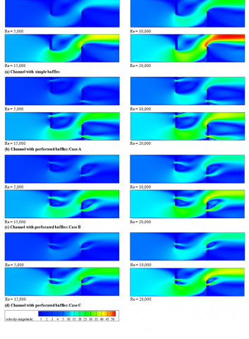
Figure 7 presents contour plots for the mean velocity fields for a hydrogen flow in the channel for two different baffle situations, simple and perforated (0.25h, 0.5h and 0.75h). Low mean velocities are observed next to the deflectors, near their downstream sides, where recycling cells are present, due to a depression in these regions. The values of the velocity are increased across the narrow spaces between the deflector and duct wall edges of the, due to the decrease in the flow surface and the rise in pressure values across these gaps. There is a large zone with very high flow velocities, above the second baffle, from its frontal upper edge to the exit, near its hot wall. This behavior is in the case of continuous simple obstacle, as shown in Figure 7a. The introduction of perforated baffles inside the channel, leads to a decrease in the flow velocity as a result of the formation of secondary currents that cross these pores, leading to a drop in pressure values through the large spaces situated between the tips of the baffles and the channel surfaces, and thus, a reduction in velocity values, and this for all perforated obstacle cases investigated. In all cases, there is a correlation between the speed and the Re.
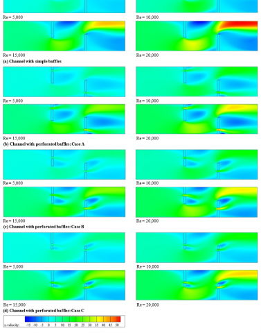
The distribution of the axial component of the velocity (u) for different cases of deflectors and Re values is addressed in Figure 8. The u values are very low in the vicinity of the deflectors, on their back sides, due to the presence of zones of cells of recycling in these regions. This was due to a decrease in the values of pressure, on the left, and right faces of these deflectors. These cells of recirculation are characterized by opposite currents and negative axial velocities. While, the values of u are high in the vicinity of the tips of the deflectors, especially next to the hot surface, at the exit (see Figure 8). The speed values also are high through gaps of the perforated baffles, and in all cases suggested; this, as a result of secondary streams flowing through these holes under high pressure. From the figure, it is very clear that the axial velocity values are very important in the case of a deflector without perforation, while the presence of perforated obstacles leads to a reduction in the u value by passing the current through their holes. As expected, and in all presented cases, the axial velocity values rise as the Re number values improve. In addition, the strength and size of recirculation zones are important for a wide Re range.
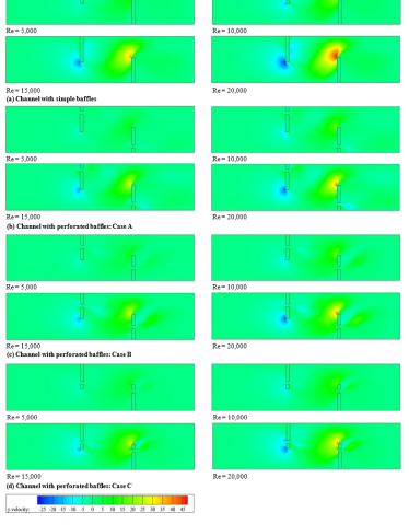
Figure 9 reports the variation of the transverse velocity vs. Re values for different obstacle geometries. The transverse speed is very low, of negative values, on the sharp edge of the front of the first baffle. This, due to the hydrogen current disturbance due to the presence of the upper obstacle, and its deviation according to the vertical axis, in the opposite direction, from the top duct section towards its bottom section, so the speed is negative. The plots in this figure also show very high values of the y-velocity. These values are situated on the front edges of the lower obstacles in all their configurations. The variation of flow rate is also shown in Figure 9 which indicates that the y-velocity enhances with the enhancement of Re number. As expected, the y-velocity reaches its maximum values in the case of the deflector without pore, for all Re values applied. This speed decreases when the perforated obstacles are inserted into the channel.
Figure 5. Variation of dynamic pressure with Re for different deflectors
Figure 6. Streamlines for various deflectors and Re numbers
Figure 7. Contours of fields of mean-velocity (V) for different deflectors and Re numbers
Figure 8. X-velocity fields for different deflectors and Re values
Figure 9. Y-velocity fields for different deflectors and Re values
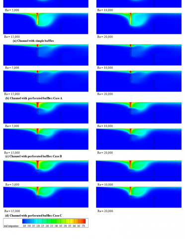
Figure 10 plots the temperature field contours for various obstacles at different Re number values. It is very clear that the hydrogen fluid temperature is very high next to the hot upper baffle, on its left side where the dead zone is located, and on its right side where the recycling cells are situated. The temperature goes down along the hot channel surface, above the top edge of the second obstacle, where the main flow is located with high speeds. Also, the temperature gradient is very important in the vicinity of the top face of the lower baffle, due to the strength and velocity of the main flow in that region, while the lower values are present in the vicinity of the first deflector due to a pressure and velocity reduction in this channel part. As expected, the temperature gradient is proportional to the number of Reynolds in all treated cases, and it is very clear that the presence of perforated baffles (or obstacles with gaps) contributes to the activation of dead areas on the left side of the fin and also to the elimination of recycling cells on its right side, especially in the A case of a gap at the bottom of the obstacle (0.25h) as shown in Figure 10b.
Figure 10. Contour plots of temperature fields for different baffles at various Re values
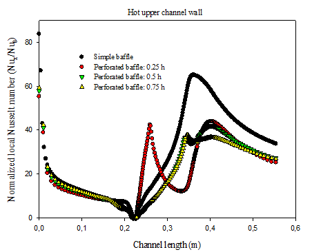
Figure 11 addresses the distribution of the Nux/Nu0 local Nusselt number ratio in the hot line starting from the inlet of the channel to its exit, at a Re value of 5,000. The Nux/Nu0 values decrease just after the channel inlet section, in all cases of baffles listed. This reduction in Nux/Nu0 values is due to the presence of the hot upper wall-attached first baffle, which directs the entire current towards the insulated lower part and creates a dead zone on its front side with poor temperature gradients and thus, a bad heat transfer. In the region starting from the right side of first baffle to the left side of the second obstacle, the Nux/Nu0 values are improved. This improvement is due to the good mixing of the fluid through the recycling cells present in the back region. Moreover, inserting the gap in the bottom part of the baffle, as reported in A case, shows an increase in the Nux/Nu0 values compared to other cases. The current flowing through the gaps mixes the hydrogen molecules and dead areas after the fin, resulting thus in the elimination of lower Nux/Nu0 regions, see A case. In the figure, the large values are found near the upper edge of the second baffle, due to the strong flow on its left side, and the presence of very strong recycling cells on its back region which force the main stream towards the hot top wall, thus gaining good thermal energy in this region. In the second obstacle regime, the introduction of a simple configuration leads to a considerable increase in the heat transfer compared with a perforated geometry; the insertion of a gap in the obstacle section yields a decrease in the heat transfer due to the absence of lower heat transfer dead zones in this part of the channel.
Figure 11. Nux/Nu0 profiles at y = H/2 for Re = 5,000
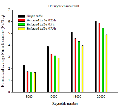
Figure 12 shows the changes of the Nu/Nu0 average Nusselt number ratio as a function of Re for different values of the gap position (dg) in the perforated baffle. The value of Nu/Nu0 augments as Re augments, regardless of the value of the gap position (dg). However, the Nu/Nu0 ratio reduces with the augmentation of the dg value, whatever the value of the Re number; consequently, the gap position of the dg = 0.25 × h value makes it possible to have a maximum thermal rate. Moreover, using the deflector with a gap of 0.25 × h position, and for the highest Re number (20,000), gives a Nu/Nu0 ratio greater than that obtained with dg = 0.5 × h and dg = 0.75 × h, for which the increase is about 8 % and 17 %, respectively. In the range of gap positions studied, from 0.25 × h to 0.75 × h, it is noted that the simple baffle without a gap makes it possible to obtain a higher Nu/Nu0 than that of a perforated baffle, and this for all the Re values studied. The baffles with gaps of 0.25 × h, 0.5 × h and 0.75 × h positions (dg) causes decreases in the heat transfer rate of about 3%, 10% and 19%, respectively, compared to that of the simple baffle.
Figure 12. Variation of Nu/Nu0 with Re
Figure 13 shows the Cf/f0 local friction coefficient ratio along the hot surface (y = H/2) for a constant Re number of 5,000, and for three different values of dg. The trends of the Cf/f0 ratio are the same for all the dg values. The Cf/f0 profiles have the highest value in the zone opposite to the baffle (lower obstacle), and the smallest value in the region close to the fin (upper obstacle), and this in all the cases considered. A simple comparison of numerical results of Figure 13 makes it possible to say that the dg gap position has an impact on the skin coefficient of friction. The highest Cf/f0 value, for all perforated baffles, is detected at dg = 0.25 × h. However, the lowest values are found with the gap position of dg = 0.75 × h (or case C). Note also that the presence of a perforated baffle causes a significant decrease in friction for all A, B and C cases, compared to the case of a simple baffle without a gap, with the smallest Re value, i.e., 5,000. This shows the interest of using a perforated baffle in order to minimize the friction in the present current channel.
Figure 13. Distribution of Cf/f0 at y = H/2 for Re = 5,000
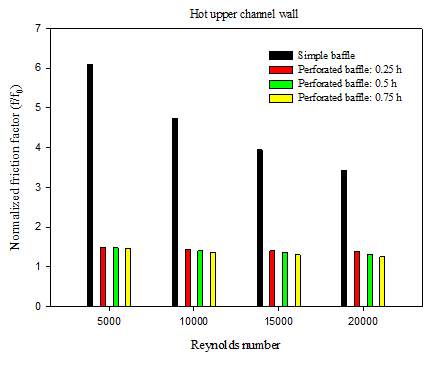
Figure 14 illustrates the evolution in the f/f0 average ratio of friction as a function of the different Re values, i.e., Re = 5,000, 10,000, 15,000 and 20,000, for two various obstacle models, i.e., simple and perforated baffles. It can be said that this friction ratio decreases when the Re augments, and this for all the studied cases; thus, the Re value of 5,000 provides the highest factor of friction. In all Re cases, the hydrogen current flow through the channel having simple or perforated baffles gives larger f values than in a smooth channel, because large recirculation regions and strong deformations are generated inside the channel with obstacles, which produces higher speed gradients. For example, at the lowest Re values (Re = 5,000), the f friction factor shows an increase of 610%, 339%, 330% and 321%, respectively, for using the simple, 0.25h, 0.5h and 0.75h perforated baffles, with respect to a smooth channel without obstacle. On the other hand, the highest friction loss was recorded for the simple baffle case; however, the lowest values are obtained in the perforated baffle case for all dg values. The use of perforated baffles in A, B and D cases shows a reduction in friction values of 44%, 46% and 47%, respectively, compared to those given by the simple baffles, for the lowest Reynolds number. This indicates that it is more advantageous to use the baffle in its perforated model.
Figure 14. Variation of f/f0 with Re
The thermal improvement factor (TEF), given by equation (43), was used to plot Figure 15. Different perforated obstacle gap positions (dg) were simulated, evaluated and then compared in this recent analysis. It should be noted that this factor increases as the Re number also increases, while the gap position decreases. The optimal factor is around 4.236, 4.112 and 3.890, respectively, the positions dg = 0.25h, 0.5h and 0.75h, and this for the maximum Re number. As a result, the improvement factors of the channel containing the perforated baffle appear to be greater than unity for all dg gap positions; they are situated between 1.143 and 4.236, and depend on the values of dg and Re, which suggests a better thermo-hydrodynamic performance compared to that obtained with a smooth channel. The largest value of this factor is obtained when dg = 0.25h, while the smallest value is found with dg = 0.75h. More specifically, the perforated baffles with dg = 0.25h gaps, at Re values of 5,000 to 20,000, give a higher thermal improvement than with dg = 0.5h and 0.75h, about 0.013-2.933% and 2.298-8.167%, respectively. For the highest Reynolds value, Re = 20,000, the TEF value in the case of a 0.75h perforated baffle decreases by 2.747% compared to the case of a simple obstacle with no gap. However, the value of this same factor increases by 5.901% and 2.794% when the value of dg is equal to 0.25h and 0.5h, respectively, for this same great value of the Reynolds number. Therefore, the perforated baffle model with a small gap position distance (dg = 0.25h) and a large Reynolds number value (Re = 20,000) can be chosen as the best geometric model for a good improvement of heat transfer with a minimal friction loss inside the channel.
Paper titles should be written in upper-case and lower-case letters, not all upper-case, e.g., “Instructions for preparing papers for International Journal of Heat and Technology”. Do not use capital letters for prepositions, articles or conjunctions unless one is the first word.
Avoid writing long formulas with subscripts in the title; short formulas that identify the elements are fine (e.g., “Nd–Fe–B”).
Figure 15. Variation of TEF with Re
The authors are very thankful to the distinguished reviewers of the journal for their insightful comments and suggestions.
[1] Sahin, B., Ates, I., Manay, E., Bayrakceken, A., Celikc, C. (2019). Optimization of design parameters for heat transfer and friction factor in a heat sink with hollow trapezoidal baffles. Applied Thermal Engineering, 154: 76-86. https://doi.org/10.1016/j.applthermaleng.2019.03.056
[2] Chang, S.W., Chen, T.W., Chen, Y.W. (2019). Detailed heat transfer and friction factor measurements for square channel enhanced by plate insert with inclined baffles and perforated slots. Applied Thermal Engineering, 159: 113856. https://doi.org/10.1016/j.applthermaleng.2019.113856
[3] Chen, Z., Ji, Z., Huang, H. (2019). Acoustic impedance of perforated plates in the presence of bias flow. Journal of Sound and Vibration, 446: 159-175. https://doi.org/10.1016/j.jsv.2019.01.031
[4] Zhang, L., Li, H., Hu, C., Zhu, Q. (2019). Prediction of distribution behavior of particles with wide size distribution in baffled fluidized beds. Powder Technology, 348: 24-32. https://doi.org/10.1016/j.powtec.2019.03.012
[5] Zhang, L., Guo, H., Wu, J., Du, W. (2012). Compound heat transfer enhancement for shell side of double-pipe heat exchanger by helical fins and vortex generators. Heat Mass Transfer, 48: 1113-1124. https://doi.org/10.1007/s00231-011-0959-5
[6] Eiamsa-ard, S., Promvonge, P. (2012). Laminar periodic flow and heat transfer in a rectangular channel with triangular wavy baffles. Journal of Thermal Science, 21: 250-261. https://doi.org/10.1007/s11630-012-0542-5
[7] Eiamsa-ard, S., Pattanapipat, S., Promvonge, P. (2013). Influence of triangular wavy baffles on heat and fluid flow characteristics in a channel. Journal of Mechanical Science and Technology, 27: 2199-2208. https://doi.org/10.1007/s12206-013-0534-8
[8] Boukhadia, K., Ameur, H., Sahel, D., Bozit, M. (2018). Effect of the perforation design on the fluid flow and heat transfer characteristics of a plate fin heat exchanger. International Journal of Thermal Sciences, 126: 172-180. https://doi.org/10.1016/j.ijthermalsci.2017.12.025
[9] Chamoli, S. (2015). ANN and RSM approach for modeling and optimization of designing parameters for a V-down perforated baffle roughened rectangular channel. Alexandria Engineering Journal, 54(3): 429-446. http://dx.doi.org/10.1016/j.aej.2015.03.018
[10] Chamoli, S. (2015). Hybrid FAHP (fuzzy analytical hierarchy process)-FTOPSIS (fuzzy technique for order preference by similarity of an ideal solution) approach for performance evaluation of the V down perforated baffle roughened rectangular channel. Energy, 84: 432-442. http://dx.doi.org/10.1016/j.energy.2015.03.007
[11] Tan, Y., He, Z., Xu, T., Fang, X., Gao, X., Zhang, Z. (2017). Experimental investigation of heat transfer and pressure drop characteristics of non-Newtonian nanofluids flowing in the shell‑side of a helical baffle heat exchanger with low-finned tubes. Heat Mass Transfer. https://doi.org/10.1007/s00231-017-2015-6
[12] Chamoli, S. (2015). A Taguchi approach for optimization of flow and geometrical parameters in a rectangular channel roughened with V down perforated baffles. Case Studies in Thermal Engineering, 5: 59-69. http://dx.doi.org/10.1016/j.csite.2015.01.001
[13] Cho, I.H., Choi, J.S., Kim, M.H. (2017). Sloshing reduction in a swaying rectangular tank by a horizontal porous baffle. Ocean Engineering, 138: 23-34. http://dx.doi.org/10.1016/j.oceaneng.2017.04.005
[14] Choi, M.K., Cho, M.K., Lee, H.W., Jung, H., Lee, J.W. (2016). Generalized equation for the design of a baffle to generate arbitrary flow velocity profiles. J. Wind Eng. Ind. Aerodyn., 149: 30-34. http://dx.doi.org/10.1016/j.jweia.2015.11.013
[15] Chu, C.R., Wu, Y.R., Wu, T.R., Wang, C.Y. (2018). Slosh-induced hydrodynamic force in a water tank with multiple baffles. Ocean Engineering, 167: 282-292. https://doi.org/10.1016/j.oceaneng.2018.08.049
[16] Wang, W.H., Cheng, D.L., Liu, T., Liu, Y.H. (2016). Performance comparison for oil-water heat transfer of circumferential overlap trisection helical baffle heat exchanger. J. Cent. South Univ., 23: 2720-2727. https://doi.org/10.1007/s11771-016-3333-4
[17] Karwa, R., Maheshwari, B.K., Karwa, N. (2005). Experimental study of heat transfer enhancement in an asymmetrically heated rectangular duct with perforated baffles. International Communications in Heat and Mass Transfer, 32(1-2): 275-284. https://doi.org/10.1016/j.icheatmasstransfer.2004.10.002
[18] Mellal, M., Benzeguir, R., Sahel, D., Ameur, H. (2017). Hydro-thermal shell-side performance evaluation of a shell and tube heat exchanger under different baffle arrangement and orientation. International Journal of Thermal Sciences, 121: 138-149. https://doi.org/10.1016/j.ijthermalsci.2017.07.011
[19] Kumar, A., Sinhamahapatra, K.P. (2016). Dynamics of rectangular tank with perforated vertical baffle. Ocean Engineering, 126: 384-401. http://dx.doi.org/10.1016/j.oceaneng.2016.09.012
[20] Kuzniatsova, M., Shimanovsky, A. (2016). Definition of rational form of lateral perforated baffle for road tanks. Procedia Engineering, 134: 72-79. https://doi.org/10.1016/j.proeng.2016.01.041
[21] Zhang, J.F., Li, B., Huang, W.J., Lei, Y.G., He, Y.L., Tao, W.Q. (2009). Experimental performance comparison of shell-side heat transfer for shell-and-tube heat exchangers with middle-overlapped helical baffles and segmental baffles. Chemical Engineering Science, 64(8): 1643-1653. https://doi.org/10.1016/j.ces.2008.12.018
[22] You, Y., Fan, A., Huang, S., Liu, W. (2012). Numerical modeling and experimental validation of heat transfer and flow resistance on the shell side of a shell-and-tube heat exchanger with flower baffles. International Journal of Heat and Mass Transfer, 55(25-26): 7561-7569. https://doi.org/10.1016/j.ijheatmasstransfer.2012.07.058
[23] Mana, A.A., Sonti, V.R. (2016). Sound radiation from a perforated panel set in a baffle with a different perforation ratio. Journal of Sound and Vibration, 372: 317-341. http://dx.doi.org/10.1016/j.jsv.2016.02.041
[24] Nanan, K., Thianpong, C., Pimsarn, M., Chuwattanakul, V., Eiamsa-ard, S. (2017). Flow and thermal mechanisms in a heat exchanger tube inserted with twisted cross-baffle turbulators. Applied Thermal Engineering, 114: 130-147. http://dx.doi.org/10.1016/j.applthermaleng.2016.11.153
[25] Sahel, D., Ameur, H., Benzeguir, R., Kamla, Y. (2016). Enhancement of heat transfer in a rectangular channel with perforated baffles. Applied Thermal Engineering, 101: 156-164. https://doi.org/10.1016/j.applthermaleng.2016.02.136
[26] Xiao, X., Zhang, L., Li, X., Jiang, B., Yang, X., Xia, Y. (2013). Numerical investigation of helical baffles heat exchanger with different Prandtl number fluids. International Journal of Heat and Mass Transfer, 63: 434-444. https://doi.org/10.1016/j.ijheatmasstransfer.2013.04.001
[27] Saravanakumar, P.T., Somasundaram, D., Matheswaran, M.M. (2019). Thermal and thermo-hydraulic analysis of arc shaped rib roughened solar air heater integrated with fins and baffles. Solar Energy, 180: 360-371. https://doi.org/10.1016/j.solener.2019.01.036
[28] Du, T., Du, W., Che, K., Cheng, L. (2015). Parametric optimization of overlapped helical baffled heat exchangers by Taguchi method. Applied Thermal Engineering, 85: 334-339. https://doi.org/10.1016/j.applthermaleng.2015.02.058
[29] Xue, M.A., Zheng, J., Lin, P., Yuan, X. (2017). Experimental study on vertical baffles of different configurations in suppressing sloshing pressure. Ocean Engineering, 136: 178-189. http://dx.doi.org/10.1016/j.oceaneng.2017.03.031
[30] Demartini, L.C., Vielmo, H.A., Möller, S.V. (2004). Numeric and experimental analysis of the turbulent flow through a channel with baffle plates. Journal of the Brazilian Society of Mechanical Sciences and Engineering, 26(2): 153-159. https://doi.org/10.1590/S1678-58782004000200006
[31] Launder, B.E., Spalding, D.B. (1974). The numerical computation of turbulent flow. Computer Methods in Applied Mechanics and Engineering, 3(2): 269-289. http://doi.org/10.1016/0045-7825(74)90029-2
[32] Dittus, F.W., Boelter, L.M.K. (1930). Heat transfer in automobile radiators of tubular type. Univ. California, Berkeley, Publ. Eng., 1(13): 755-758.
[33] Petukhov, B.S. (1970). Heat transfer and friction in turbulent pipe flow with variable physical properties. Advances in Heat Transfer, 6: 503-564. https://doi.org/10.1016/S0065-2717(08)70153-9
[34] Patankar, S.V. (1980). Numerical heat transfer and fluid flow, Hemisphere, New York, USA.
[35] Leonard, B.P., Mokhtari, S. (1990). Ultra-sharp nonoscillatory convection schemes for high-speed steady multidimensional flow. NASA TM 1-2568, NASA Lewis Research Center.