Wei Lu | Junlin Wang | Hua Guo | Hongmei Li | Jianheng Sun*
© 2020 IIETA. This article is published by IIETA and is licensed under the CC BY 4.0 license (http://creativecommons.org/licenses/by/4.0/).
OPEN ACCESS
Long-span lightweight single-layer reticulated shell structure as a typical wind-load-sensitive structure, Wind load is the main control load of its structural design, and unfavorable wind load distribution is likely to cause it to collapse. Considering buckling of compression members and successive failure of tension members, a numerical analysis model of global dynamic collapse of single-layer cylindrical reticulated shell structure with roof panels and support columns is established by using the finite element explicit analysis software and self-compiled pre-post-processing program. The internal forces of members, the maximum displacement of nodes and the deformed configuration of structure are taken as the characteristic responses, the collapse process and the collapse mechanism of reticulated shell are analyzed from different angles. The quantitative effects of roof panels and support columns on the wind-induced dynamic collapse of reticulated shell structure are investigated. The analysis results show that the critical load factor corresponding to the dynamic collapse of reticulated shell structure without roof panels has a significant decrease of about 20%, and the time of dynamic collapse of reticulated shell structure is obviously advanced with support columns. It is necessary to consider the influence of roof panels and support columns in the dynamic collapse analysis of reticulated shell structure under wind loads. Otherwise, the safety assessment of reticulated structures under wind loads will be uncertainties. Based on the research results, some conclusions are suggested for the engineering design and wind-resistant and disaster-prevention of single-layer reticulated shell structures.
single-layer cylindrical reticulated shell, roof slabs, support columns, wind load, collapse
With the global warming, the frequency of windstorms has become higher, making secondary disasters more serious and affecting a wider range, which has brought huge loss of property and life to human beings. The study of wind resistance in civil engineering structures has become a very important subject in the field of disaster prevention and mitigation. The dynamic response of structure under strong winds, especially the dynamic collapse is one of the control loads for the applicability and safety of large-span lightweight reticulated shell structure [1]. In the past thirty years of research, reticulated shell structures have been extensively studied by using both numerical simulations and modal experiments. The static stability performance of single-layer latticed shell structures has been analyzed by Gioncu et al. [2-6] and the dynamic stability performance has been described by Yanagisawa et al. [7-11]. However, the studies on the dynamic stability performance of reticulated shell structures under wind loads are rarely described in these studies. It is necessary to analyze the wind-induced dynamic collapse performance of single-layer reticulated shell structures.
In the study of wind-induced dynamic response, Li et al. analyzed the nonlinear dynamic response and vibration characteristics of single-layer spherical reticulated shell structures under wind loads [12-16]; Sun et al. investigated the three-dimensional wind- induced dynamic response analysis of single-layer reticulated shell structures under wind loads [17, 18]. The variation law of displacement wind vibration coefficient and internal force wind vibration coefficient is pointed out, then the calculation formula of displacement wind vibration coefficient and internal force wind vibration coefficient is regressed. Further, the wind-induced elastic-plastic failure whole process of single-layer reticulated shells to determine the critical wind speed of dynamic failure of reticulated shell structures were studied, and the quantitative influencing factors of critical wind speed were analyzed. Xie et al. [19] the characteristics of the dynamic response of suspendome under wind load were obtained by numerically simulating the dynamic performance of suspendome under typhoons in two regions in the time domain. Combined with the dynamic response characteristics of suspendome, the maximum node displacement, the ratio of plastic members and the cable slack are used as indicators to propose the criteria for determining the dynamic failure of suspendome under typhoons. Huang and Gu [20] studied the wind pressure distribution law of single-layer cylindrical reticulated shells under different wind direction angles through wind tunnel experiments, and further studied its displacement stability behavior. Yu et al. [21] studied the wind-induced dynamic collapse performance of double-layer cylindrical reticulated shell structures, established the control index of structural collapse damage, and optimized the structural parameters of reticulated shells. However, there are three main problems in the above research: First, the effect and influence of the support columns on the upper reticulated shell structure are not considered. Second, the deflection of the rod and the failure of the tie rod were not considered during the analysis. Third, the lateral restraint effect of roof slabs on the reticulated shell member is not considered.
In this paper, the fine models of three-dimensional grids single-layer cylindrical reticulated shells are taken as the research object, and the wind-induced dynamic collapse of cylindrical reticulated shell structure is carried out by using the universal explicit finite element analysis software ANSYS/LS-DYNA. The whole process analysis was carried out to investigate the influence of the roof slabs and support columns on the dynamic collapse performance of reticulated shell structure under wind load.
2.1 Reticulated shell finite element model
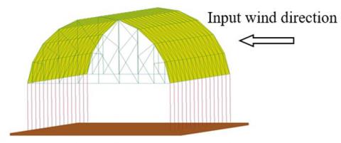
The upper structure of the analysis model is a three-dimensional grid single-layer cylindrical reticulated shell with a longitudinal length of 45 m, an arc span of 30 m and a height of 13.5 m. The supporting structure consists of 32 steel pipe columns with a height of 10 m, as shown in Figure 1. The rod of reticulated shell are the circular steel tube with size of Φ121 mm×8 mm, the side beam is a rectangular steel tube with a cross-sectional dimension of 240 mm×240 mm×10 mm×8 mm, and the support column is a circular steel tube with a cross-sectional dimension of Φ500 mm×20 mm, all of which are simulated by Beam161 element, and divided into 4 parts. The roof panel is a steel plate with a thickness of 2 mm, which is simulated by shell 163 unit; the roof load applied to the joint is simplified to Mass166 element. The rigid ground is simulated with Solid164 element, and the connections of all elements are assumed to be rigid connections.
The selected steel has a yield strength of 235 MPa, an elastic modulus of 206 GPa, a Poisson's ratio of 0.3, and a density of 7850 kg/m3. The corresponding material model uses the Plastic-Kinematic model, which uses the Cowper-Symonds criterion to investigate the effect of strain rate on the material yield stress. Assuming a material failure strain of 0.02, if the effective plastic strain of a unit reaches 0.02, the program will automatically delete the unit during the solution process. The Mat-Rigid material model was used to simulate rigid ground. The damping model is assumed to be the Reyleigh model. During the vibration and collapse process, there may be a collision between the failed unit and the adjacent member, the falling member and the rigid ground, and the automatic single-sided contact is used to simulate the contact between the different members.
Figure 1. A whole model of cylindrical reticulated shell structure
2.2 Wind load time history model
The auto-regressive filter model method (hereinafter referred to as the AR method) is used to simulate the wind load. According to the load code specification of building structure in China, the wind-induced dynamic response analysis is carried out with the wind direction as shown in the Figure 1. The wind speed-time curve of the 91 node at the standard wind speed v10=21.6 m/s is shown in Figure 2. The simulation of the pulsating wind speed time history by AR method makes the power spectrum simulation function and the objective function agree well, indicating that the method is applicable to the pulsating wind speed of each node in the simulated reticulated shell structure [17]. Regardless of the spatial correlation of the wind load, the critical wind speed caused the failure of reticulated shell structure is reduced less, and the input data of the wind load is significantly larger. In order to simplify the analysis, the wind loads of each node of reticulated shell structure are input according to the wind speed time history of a certain node [17, 18].
The wind load time history applied to each node of large span reticulated shell structures can be described as:
$F(x,y,z,t)=\lambda {{F}_{0}}(x,y,z,t)$ (1)
$\lambda {{F}_{0}}(x,y,z,t)\text{=}{{\mu }_{zi}}{{\mu }_{si}}{{w}_{i}}(t){{A}_{i}}$ (2)
${{w}_{i}}(t)\text{=}\rho {{({{\bar{v}}_{i}}+{{v}_{i}}(t))}^{2}}$ (3)
where, F is the wind load acting on the system; λ is the load factor; F0 is the initial wind load applied to the system, that is, the wind load converted by the basic wind pressure; mzi and msi are the wind pressure height variation coefficient and wind load shape coefficient at the node, which can be found in the specification; Ai is the equivalent wind area at the node i; wi(t) is the basic wind pressure at the node i; ρ is the air density; $\overline{\mathcal{v}}_{i}$ is the average wind speed; vi(t) is the pulsating wind speed.
Figure 2. Wind speed-time curve of a node
2.3 Dynamic response analysis method
The theoretical basis of dynamic response analysis using the finite element method is the classical Hamilton principle, which is expressed as follows:
$\delta {{J}_{H}}=\delta \int\limits_{{{t}_{1}}}^{{{t}_{2}}}{Ldt}=\delta \int\limits_{{{t}_{1}}}^{{{t}_{2}}}{\delta (T-V)dt=0}$ (4)
$\delta J_{H}^{'}=\delta \int\limits_{{{t}_{1}}}^{{{t}_{2}}}{Ldt}=\int\limits_{{{t}_{1}}}^{{{t}_{2}}}{\delta (T-V)dt+\int\limits_{{{t}_{1}}}^{{{t}_{2}}}{\delta {{W}_{nc}}dt=0}}$ (5)
where, JH is the Hamilton action; L is the Lagrange function; T is the total kinetic energy of the system; V is the strain energy of the system and the potential energy of the conserved external force; δ is the variation taken in the specified time interval. J' H is the corrected Hamiltonian action; Wnc is the work done by the non-conservative forces on the system.
The equation (5) is discretized into the dynamic equilibrium equation of the system as follows:
$\mathbf{M\ddot{u}}(t)+\mathbf{C\dot{u}}(t)+\mathbf{Ku}(t)=\mathbf{F}(t)$ (6)
where, M is the mass matrix of the system, C is the damping matrix of the system, K is the stiffness matrix of the system, F is the dynamic load array applied to the system, and u is the displacement array of the system. It is very difficult to accurately determine the damping matrix during the analysis. Generally, Rayleigh damping is used in advance, which is simplified as a linear combination of the sum, that is:
$\mathbf{C}=\alpha \mathbf{M}+\beta \mathbf{K}$ (7)
In the formula, α and β are the mass damping coefficient and stiffness damping coefficient, respectively. The determination methods are as follows:
$\alpha =\frac{2{{\omega }_{i}}{{\omega }_{j}}\left( {{\xi }_{i}}{{\omega }_{j}}-{{\xi }_{j}}{{\omega }_{i}} \right)}{{{\omega }_{j}}^{2}-{{\omega }_{i}}^{2}}$ (8a)
$\beta =\frac{2\left( {{\xi }_{j}}{{\omega }_{j}}-{{\xi }_{i}}{{\omega }_{i}} \right)}{{{\omega }_{j}}^{2}-{{\omega }_{i}}^{2}}$ (8b)
In the formula, ωi and ωj are the circular frequencies corresponding to the i and j main-mode modes of the structure vibration, respectively; ξi and ξj are damping ratios corresponding to the i and j main-mode modes of the structure, respectively, which are usually determined experimentally. For the measured value of the damping ratio of steel structures, it is generally in the range of 0.015 ~ 0.025. In China's current building structure load codes, the damping ratio of steel structures is recommended to be 0.02.
3.1 Collapse mechanism under wind load
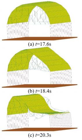
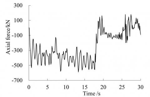
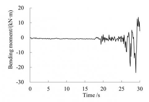
The IDA method is employed to analyze the dynamic collapse. Taking the initial wind load as the reference value, the wind load acting on reticulated shell structure is continuously increased by changing the load factor. Combined with the failure criterion of Hsu S. C. and the overall deformation form of structure, the critical load coefficient of dynamic collapse is determined. The calculation results show that the equilibrium position of the node vibration is greatly offset from the original position when the load coefficient λ is 10, and combined with the overall deformation diagram of reticulated shell structure, it can be considered that the reticulated shell structure collapsed. The deformation patterns of reticulated shell structure at different times are shown in Figure 3, as the load factor λ is 10. The displacement-time curve, the unit axial force time history curve and the bending moment time history curve of reticulated shell structure are shown in Figure 4 ~ Figure 6, respectively. The collapse process of reticulated shell structure can be divided into the following three stages.
The first stage is from the beginning to 17.6s. At this stage, the rod members are generally elastically deformed, and a portion of the rod portion at both ends of the traverse and the compression areas adjacent to the traverse are subjected to yield deformation. The members and roof slabs of reticulated shell structure will not break. From the perspective of internal force, the axial force in the members of reticulated shell is dominant, and the bending moment is very small, as shown in Figure 5 and Figure 6. At this stage, the wind-induced reciprocating vibration causes the breadth and depth of structural damage to develop continuously. The vibration equilibrium position of the upper part of reticulated shell structure will be slightly displaced along the incoming wind direction, but no obvious local collapse area is formed. The deformation and mechanical parameters of rods are still continuous and the structure remains intact. This stage is a mild damage stage.
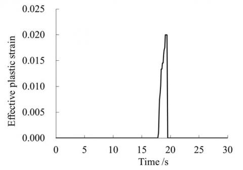
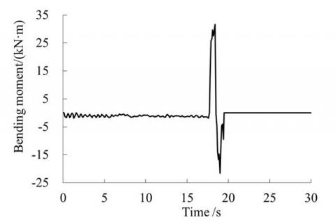
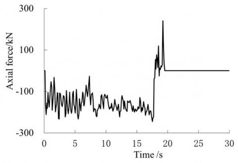
The second stage is from 17.6s to 18.4s, which lasts about 0.8s. The mechanical characteristics of this stage changed significantly. The internal force components of the rods at both ends of reticulated shell structure change rapidly, that is, the proportion of the axial force of the rod decreases, and the proportion of the bending moment increases, as shown in Figure 5 and Figure 6. The geometry of reticulated shell is adapted to its mechanical characteristics, which is characterized by the depression of the windward side and the uplift of the leeward side. At t=17.9s, the members of the compression zone at the end of reticulated shell reach the failure strain of 0.02; then the unit fails for 0.1s, and the bending moment and the axial force are all unloaded from 18.7kN·m and 12.0kN to 0. The members exit the calculation, as shown in Figure 7 ~ Figure 9. The formation of the collapsed area is the result of the higher degree of plastic accumulation of the members and the buckling of the compression members. The pressure-receiving area is transmitted from the lower part of reticulated shell to the top, and the acreage of the trough-receiving area of reticulated shell structure is gradually squeezed. The geometry that is adapted to the change of internal force is obviously offset from the original position, and the integrity of reticulated shell structure is obviously broken, and the overall stiffness is weakened. The continuous action of the wind load causes the collapsed area to begin to form and develop rapidly. This stage is the stage of collapse formation.
The third stage is after 18.4s. At t=18.4s, the plastic strain of the cross-members at both ends of reticulated shell structure reaches the failure strain, and the fracture failure of the rod begins to occur. Under the action of continuous wind force, the members and roof slabs connected to the support columns are successively torn and failed, and the collapsed area is rapidly expanded. After 20.3s, the collapsed area completely separate from the support columns, and the structural integrity is completely lost, eventually leading to collapse. The mechanical characteristics and geometrical shape of reticulated shell structure have undergone profound changes, and the continuity of the mechanical parameters has been destroyed as more and more members break. At this time, reticulated shell structure forms a wind-induced overall collapse in the engineering sense, which is the overall collapse stage.
Figure 3. Deformation form of reticulated shell structure at different times
Figure 4. Displacement-time history of a node
Figure 5. Axial force time history of the member of the central compression zone
Figure 6. Moment time history of the member of the central compression zone
Figure 7. Axial force time history of the unit in the end compression zone
Figure 8. Moment axial force time history of the end compression zone
Figure 9. Strain time history of the unit in the end compression zone
3.2 Influence of roof slabs on reticulated shell structure
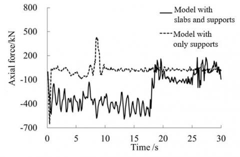
Taking other conditions and parameters as the same, the calculation results of the model of reticulated shell structure without roof slabs but with support columns are compared with that of the model of reticulated shell structure with roof slabs and support columns. When the load coefficient λ=8, the displacement time history curves of nodes, the axial forces of unit and the moment time history curves corresponding to the models of the two types of reticulated shell structures are as shown in Figure 10 ~ Figure 12, respectively. The calculation results show that the wind load critical coefficient of the model with roof slabs and support columns is reduced by about 20% compared with that of the model without roof slabs but with support columns, mainly due to the in-plane restraining effect of roof slabs on the members of reticulated shell structure. It can be seen from Figure 11 and Figure 12 that the axial force-moment ratio of members of structure with roof slabs is significantly larger than that of no roof slabs constraint.
Figure 10. Displacement-time history of the node
Figure 11. Axial force time history of the member of central compression zone
Figure 12. Moment time history of the member of central compression zone
3.3 Influence of the lower support columns on the upper reticulated shell
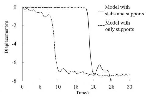
In the same way, taking other conditions and parameters as the same, the calculation results of the reticulated shell model without the roof slab and the support columns are compared with the results of the model without roof slabs but with support columns mentioned above. The displacement time curves of nodes of the two types of models are shown in Figure 13. The results show that the model without roof slabs and support columns collapses when the load coefficient λ=10. The load coefficient of the dynamic collapse of reticulated shell structure with support columns or not is approximately the same, mainly because the rigidity of the support columns is relatively large. However, the collapse time of reticulated shell structure with support columns is obviously advanced, and the peak time of the axial force and moment of the members is significantly earlier than that of the model without support columns, as shown in Figure 14 and Figure 15.
Figure 13. Displacement-time history of the node
Figure 14. Axial force time history of the member of central compression zone
Figure 15. Moment time history of the member of central compression zone
(1) The fine models for the dynamic collapse analysis of single-layer cylindrical reticulated shells considering roof slabs and support columns are established, and the dynamic collapse process is analyzed. The collapse process of reticulated shell structure is divided into three stages: a mild damage stage, a collapse formation stage, and an overall collapse stage. According to the failure criterion of Hsu S. C. and the overall deformation form of structure, the critical load coefficient of dynamic collapse of reticulated shell structure is determined.
(2) Comparing with the model without roof slab, the critical coefficient of the model with roof slab is reduced by about 20%. Therefore, regardless of the influence of roof slabs, it is conservative when considering the wind-induced dynamic collapse of reticulated shell structure. Comparing with reticulated shell structure without support columns, the result shows that the collapse time of reticulated shell structure with the support columns is obviously advanced. Regardless of the influence of support columns, it is easy to bring a safety hazard when evaluating the wind-induced dynamic collapse performance of reticulated shell structure.
The author(s) disclosed receipt of the following financial support for the research, authorship, and/or publication of this article: This work was supported by Natural Fund of Hebei Province (No. E2018204019); Education Youth Fund of Hebei Provincial Education Department (No. QN2018256 and ZC2016142) and Science and Engineering Fund of Hebei Agricultural University (No. LG201713 and ZD201704).
[1] Khanduri, A.C., Stathopoulos, T., Bédard, C. (1998). Wind-induced interference effects on buildings-a review of the state-of-the-art. Engineering structures, 20(7): 617-630. https://doi.org/10.1016/S0141-0296(97)00066-7
[2] Gioncu, V., Balut, N. (1992). Instability behavior of single layer reticulated shells. International Journal of Space Structures, 7(4): 243-252. https://doi.org/10.1177/026635119200700402
[3] Liu, H., Zhang, W., Yuan, H. (2016). Structural stability analysis of single-layer reticulated shells with stochastic imperfections. Engineering Structures, 124: 473-479. https://doi.org/10.1016/j.engstruct.2016.06.046
[4] He, Y., Zhou, X., Liu, D. (2014). Research on stability of single-layer inverted catenary cylindrical reticulated shells. Thin-Walled Structures, 82: 233-244. https://dx.doi.org/10.1016/j.tws.2014.04.017
[5] Fan, F., Cao, Z., Shen, S. (2010). Elasto-plastic stability of single-layer reticulated shells. Thin-Walled Structures, 48(10-11): 827-836. https://doi.org/10.1016/j.tws.2010.04.004
[6] Yuji, T., Shiro, K., Shoji, N. (2017). Buckling strength maximization of single layer free-form reticulated shells. Journal of Structural and Construction Engineering, 733(82): 441-450. https://doi.org/10.3130/aijs.82.441
[7] Yanagisawa, T., Kato, S. (2017). Reliability analysis of buckling strength of single layer reticulated domes under severe earthquakes. Journal of the International Association for Shell and Spatial Structures, 58(3): 189-205. https://doi.org/10.20898/j.iass.2017.193.840
[8] Taniguchi, Y., Matsui, T., Yoshinaka, S. (2018). Comparison study of elasto-plastic behavior on static and dynamic responses for single layer lattice domes under vertical loading. Journal of Structural and Construction Engineering, 747(83): 709-716. https://doi.org/10.3130/aijs.83.709
[9] Sun, J., Li, H., Nooshin, H., Parke, G.A. (2014). Dynamic stability behaviour of lattice domes with substructures. International Journal of Space Structures, 29(1): 1-7. https://doi.org/10.1260/0266-3511.29.1.1
[10] Yang, D., Yun, C., Wu, J., Yao, Y. (2018). Seismic response and failure mechanism of single-layer latticed domes with steel columns and braces as substructures. Thin-Walled Structures, 124: 458-467. https://doi.org/10.1016/j.tws.2017.12.038
[11] Ding, Y., Chen, Z.T., Zong, L., Yan, J.B. (2017). A theoretical strut model for severe seismic analysis of single-layer reticulated domes. Journal of Constructional Steel Research, 128: 661-671. https://doi.org/10.1016/j.jcsr.2016.09.022
[12] Li, Y.Q., Tamura, Y. (2004). Wind-resistant analysis for large-span single-layer reticulated shells. International Journal of Space Structures, 19(1): 47-59. https://doi.org/10.1260/026635104322988362
[13] Li, Y.Q., Tamura, Y., Yoshida, A., Katsumura, A., Cho, K. (2006). Wind loading and its effects on single-layer reticulated cylindrical shells. Journal of wind engineering and industrial aerodynamics, 94(12): 949-973. https://doi.org/10.1016/j.jweia.2006.04.004
[14] Li, Y.Q., Tamura, Y. (2005). Nonlinear dynamic analysis for large-span single-layer reticulated shells subjected to wind loading. Wind and Structures, 8(1): 35-48. https://doi.org/10.12989/was.2005.8.1.035
[15] Uematsu, Y., Yamada, M., Inoue, A., Hongo, T. (1997). Wind loads and wind-induced dynamic behavior of a single-layer latticed dome. Journal of wind engineering and industrial aerodynamics, 66(3): 227-248. https://doi.org/10.1016/S0167-6105(97)00133-5
[16] Uematsu, Y., Sone, T., Yamada, M., Hongo, T. (2002). Wind-induced dynamic response and its load estimation for structural frames of single-layer latticed domes with long spans. Wind and Structures, 5(6): 543-562. https://doi.org/10.12989/was.2002.5.6.543
[17] Wang, J.L., Li, H.M., Ren, X.Q., Sun, J.S., Sun, C., Lu, W. (2012). Wind-induced vibration coefficient and parametric analysis of single-layer cylindrical reticulated shell structures. Journal of Hebei Agriculture University, 35(3): 125-130. https://doi.org/10.3969/j.issn.1000-1573.2012.03.024
[18] Ye, J.H., Zhang, M. (2019). Discrete element method for elastoplastic buckling analysis of single-layer reticulated shells. Engineering Mechanics, 36(7): 30-37, 47. https://doi.org/10.6052/j.issn.1000-4750.2018.10.0374
[19] Xie, E.X., Yuan, X.F., Chen, C. (2017). Analysis of dynamic failure of suspendome under typhoon load. Journal of Zhejiang University, 51(2): 238-244. https://doi.org/10.3785/j.issn.1008-973X.2017.02.003
[20] Huang, Y.Q., Gu, M. (2011). Dynamic instability of a single-layer cylindrical reticulated shell under wind loads. Journal of Vibration and Shock, 30(2): 39-43.
[21] Yu, Y., Wang, J.Z., Zhu, X.Y. (2015). Collapse analysis of double layer cylindrical reticulated shell under strong wind based on finite particle method. Journal of Southeast University, 45(4): 756-762. https://doi.org/10.3969/j.issn.1001-0505.2015.04.025