Hisham H. Jasim
© 2020 IIETA. This article is published by IIETA and is licensed under the CC BY 4.0 license (http://creativecommons.org/licenses/by/4.0/).
OPEN ACCESS
Each type of fin has been investigated separately in many researches that are concerned with finding its performance under varying operating conditions, enhancement of heat sink performance by using the combination between two types of fin was investigated in this study. To establish a scientific comparison between models, a constant weight of the heat sink has been imposed. For that the total size of the original model (longitudinal-fin) was stabilized.
Converting part of the original size into spin fins led to the emergence of a hybrid design that was studied by analytical and computational simulation. Under natural convection and Ra=107, calculation process was performed for varying the surface area between (1-1.8) times.
The strong agreement of the validation results (0.31 %-0.52 %) showed the reliability of the analytical model based on the ANSYS simulation. Hence, the results demonstrated that the hybrid designs have a discrimination in several aspects; reducing the fin temperatures is about (2.7% to 8.8%), lower thermal resistance by (24% to 46%) and augmentation of heat transferred by (31% -80%), compared with original heat sink.
Improvement of thermal resistance and heat transferred does not behave in the same approach with all models (area ratio of greater than 1.6), because of the overlap between the negative effect of convection coefficient and increase of surface area. So, the approximate steady state can be happened.
natural convection heat transfer, heat sink, hybrid fin design, heat transfer enhancement
Thermal analysis of the heat sink is the study to find the best performance of heat generated components with respect to the behavior of different parameters in a variety of thermal environments. Today the systems have different possibilities, which in turn need to complex electronic systems with high packing densities. In other words, the thermal problems are increasing. Therefore, a growing number of engineering applications are concerned with the rapid movement of heat transfer. Extended surface is used as a heat sink to remove the heat from electrical and electronic equipments that are found in different applications.
In order to remove the heat from generation sources, efficient cooling systems are applied to keeping the devices in minimum temperatures [1]. Generally, active and passive cooling are used as main solutions to transfer the heat generated. According to the active cooling, forced moving fluid is required to absorb heat generated in electronics packages [2, 3]. Likewise, other applications using the free convection and radiation effects to get rid the generated heat to the surrounding region [4, 5].
More specifically, a comparison between a new design of plate cubic pin-fin heat sink and normal design plate pin-fin heat sinks were investigated experimentally.
As can be concluded from the results, by using the new design, heat transfer augmented by about 41.6% with increases of Ra towards 9.5*106. While, thermal resistance was lowered by 12% of plate cubic pin-fin heat sink. Because of rough surfaces that led to the fluid fluctuation in sublayer regions. Also, thermal resistance can be decreased with the increases of fin spacing [6].
Many research ideas depended on the consolidation between two types of fins. To estimate the optimum shapes for the longitudinal and spine fully wet fins, conjugate gradient method was adopted. The results indicate that the optimum parameters (efficiency and fin shape) will be changed according to the Biot number value. Moreover, greatly improvement can occur in case of spine fully wet fins, compared with longitudinal fin [7]. Two papers [8, 9] related to the plate circular pin fins heat sink were investigated to study the thermal performance and pressure drop. The supplementary part deals with the hydraulic performance based on the shape and arrangement of pin fins. The results illustrated, the rise in pressure drop and thermal resistance is declining when compared with pin fins heat sink. Furthermore, governing equations of elliptical pins between plate fins in-line arrangement was solved based on the k-ε turbulence model. However, the Nusselt number and thermal resistance of modified design improve and inversely proportional with elliptical pins radiuses [10].
Some research work has focused on the improvement of longitudinal-fin performance. Where it was used the numerical simulation and experimental test to show that the highest cooling performance of the longitudinal heat sink under natural convection when its mounting angle is 90o [11]. While other researchers tried to develop spins fin-heat sink. The fin efficiency ratio of cylindrical micro-fin heat sink becomes greater than unity with artificial surface roughness [12]. Varying results (Nu-Re and f-Re) of hexagonal finned heat sinks proved that the friction factor decreases and Nusselt number enhanced with increasing Reynolds number [13].
The current research objective is to make the desired improvement without any change in weight of the longitudinal-fin heat sink by stabilizing the total size. Consequently, Hybrid geometry based on a combination between longitudinal and spine fins is presented in this work as a new approach to improve the heat transfer of heat sink based on the improve of heat transfer area.
2.1 Geometric model
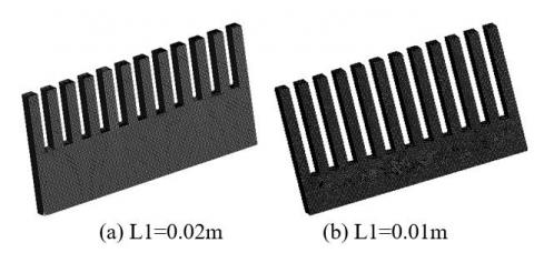
To achieve the current research goal, should be changed part of the original model to another shape on a requirement of improving the surface area. Accordingly, part of original volume was switching to spin fins with varying length based on the remaining length (L1) of longitudinal part. Meanwhile, a size value of the longitudinal –fin was installed. Figures 1(a) and 1(b) shows the original and hybrid design, respectively.
Figure 1. (a) Original heat sink; (b) Hybrid heat sink
The number and cross section area of the spin fin can be determined depending on the thickness (t) and width (w) of the original design. According to constant size of heat sink, length of spin fin can be calculated as follows:
L2=w(L−L1)t∗NO. (1)
where, NO.= number of spin fins. In this work, the fins were identified with 12 spins agreeing with the space between the fins.
2.2 General solution
The thermal analysis of any fin depended on the assumptions that are employed to define and simplify the problem to get the general solution. The heat transfer analysis conducted in this study relied on the following assumptions [14].
(1) Steady heat conduction with no heat generation.
(2) 1-D heat transfer analysis of fin height.
(3) Constant conductivity (k=200 W/m.K) and constant base temperature.
(4) Insulation of the fin tip at a corrected length, and the radiation effects are neglected.
(5) Uniform ambient temperature and uniform convection heat transfer coefficient.
The general solution was formulated by applying the steady-state heat balance Eq. (2) over the differential element [15, 16]. This differential element of height (dL) is parallel to the fin base (w*t).
ddx(Acond.dθdx)dx=h.Pkθ.dx (2)
The arbitrary constants were eliminated by substituting the boundary conditions Eq. (3) into the general solution to get the temperature distribution Eq. (4).
θ(x=0)=θbdθ(x=LTc)dx=0} (3)
θ(x)=
C1cosh(mi.x)+C2sinh(mi.x)……i=1,2 (4)
where:
θ=T(x)−Tair ;θb=Tb−Tair ;
mi=√h.Pk.A;C1=θb……(0≤x≤L1)
C2=θb[m1cosh[m2(LTc−L1)]X1]−coth(m1.L1]…(0≤x≤L1)
X1=[m1cosh[m2(LTC−L1)]cosh(m1.L1)+m2sinh[m2(LTC−L1)sinh(m1.L1)]sinh(m1.L1)
C1=θb[m1cosh[m2.LTc]X2]……(L1<x≤LTc)
X2=[m1cosh[m2(LTC−L1)]cosh(m1.L1)+m2sinh[m2(LTC−L1)]]sinh(m1.L1)
C2=−C1tanh(m2.LTc)………(L1<x≤LTc)
Several widely available results can be gotten depending on the computational solver program. Here, MATLAB was used to calculate the temperature distribution and other thermal parameters according to geometric and thermal properties (Table 1) that are compensated in the general solution equation. For inference of convection coefficient value, Empirical correlation and what it contains of dimension-less numbers were considered [17, 18].
Table 1. Specifications of the geometric models
|
Geometric parameters |
||||
|
w(mm) |
t(mm) |
NO. |
L(mm) |
L1(mm) |
|
69 |
3 |
12 |
30 |
5-25 |
|
Thermal properties |
|||
|
k |
TboC |
Tair oC |
Ra |
|
200 |
70 |
25 |
107 |
The ANSYS 16 steady-state thermal is carried out to simulate the thermal analysis of heat sink. Based on the boundary conditions and assumptions that are described above, the energy equation of the pin -longitudinal fin can be stated as below:
kd2Tdx2=0 (5)
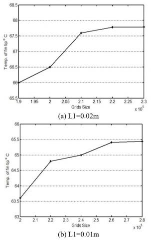
A heigh accurate grid is required for independent results. For that, several grids were tested to ensure that the study is steady-state. Figure (2) shown the grid configuration of model design. To obtain the appropriate grid, The lowest temperature (at fin tip) has been adopted as a measure of the successful grid as shown in Figure (3).
Figure 2. Grids configuration
Figure 3. Grids independent test
4.1 Validation of the general solution
To validate the present general solution, the results of the analytical model and computational simulation were compared. Validation procedure deals with the same geometric parameters and thermal properties to show the accuracy of work. The results are compared at the optimum grid size of each case. The temperature distribution of hybrid design (θ/θb) along the fin was adopted to demonstrate the convergence between the comparison results.
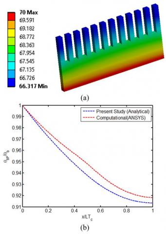
Figure 4. (a) Geometric configurations of the computational simulation. (b) Comparison between the present study and ANSYS results for L1=0.02m
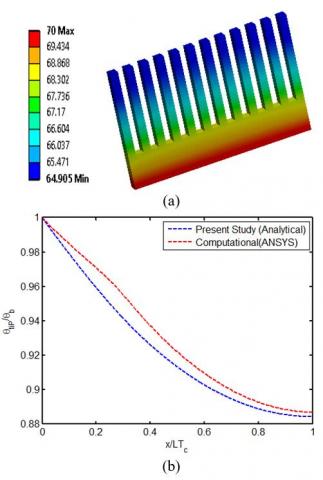
Figure 5. (a) Geometric configurations of the computational simulation. (b) Comparison between the present study and ANSYS results for L1=0.01m
Comparison between the analytical model and Computational simulation is shown in Figure 4 and 5 for L1=0.02m and L1=0.01m, respectively. Analytical results of temperature distribution using the general solution agree well with the numerical results (ANSYS) and maximum difference do not exceed (0.3%).
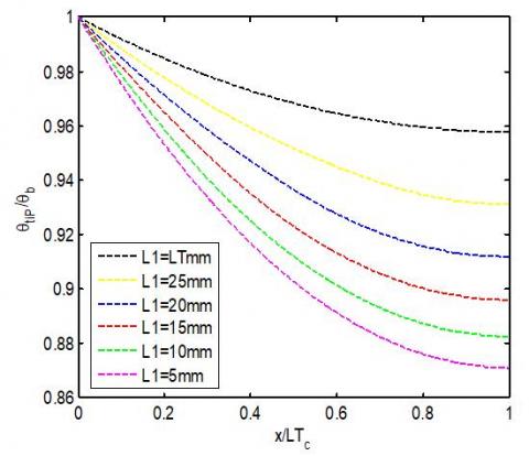
4.2 Behavior of temperature distribution
Temperature distribution is illustrated in Figure 4 and 5. Maximum temperature appears at the heat sink base while the temperature profile is down towards the fin tip. The greater temperature drop towards minimum value represent the important characteristic of the heat sink performance. This can be achieved when using a hybrid design with a small length of spins fin. Likewise, additional improvement can occur if the spin length increasing as shown in Figure 6, the results show percent improvement is between (2.7% to 8.8%).
In this study the total size was stabilized, while the shape of the model was changed depending on the conversion part of the longitudinal fin to the spin fins. This technique led to increase both of surface area contact with cooling fluid and the height of the fin. This update in model shape explains the reason for the improvement of temperature approach that is associated with the hybrid model.
Figure 6. Variation of temperature distribution with the fin length (analytical results)
4.3 Performance of heat transferred
By using the hybrid design, temperature distribution was improved . Which leads to increase the amount of heat transfer according to the general Eq. (6). Additionally, other parameters (like convection coefficient) effect on heat transfer mode and causing nonlinear change as shown in Figure (7) with increasing of area ratio. The results show, increasing in heat transfer to a greater extent with area ratio (A*) less than 1.6. Then, the approximate steady state can be happened as a result of the overlap between the negative effect of convection coefficient and growing of surface area. Indeed, heat transferred is augmented by (31% -80%), compared with original heat sink (A*=1).
Qact=−k.A(dθdx)x=0 (6)
A∗= surface area of hybrid model surface area of original model (7)
Figure 7. Change of heat transferred behavior with area ratio
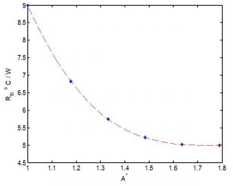
4.4 Changes in the thermal resistance value
Eq. (8) is used to calculate the thermal resistance. While, Changes of thermal resistance with area ratio is shown in Figure (8). It can be seen that as area ratio increase, thermal resistance decreases. Additionally, thermal resistance decreases with greater value at A*=1 (longitudinal fin only) when compared with other values of hybrid models. Furthermore, thermal resistance is lowered by (24% to 46%) . This phenomenon occurs, because of the great modernization in the geometric distribution of the hybrid model. Furthermore, the convergent changes are shown at A* >1.6 which in turn leads to an understand the behavior of heat transmitted around this value.
Rth=LT∑nj=1√h.P.k.AΔxtanh(∑nj=1√h.Pk.AΔx) (8)
Figure 8. Variation of thermal resistance with area ratio
Weight stabilization followed by a fixed size is the main objective that adopted for heat sink when the improvement requirements are applied. Consequently, This study was proposed the use of hybrid design to investigate the thermal performance of heat sink according to the combination between longitudinal and spins fin at the same axis of heat transfer.
Analytical analysis and numerical solution are applied to find the mathematical model, simulation of thermal approach and get diverse results. Moreover, the validation result, revealed about the excellent reliability of the analytic model based on a high level of agreement between compared results.
Many advantages can be achieved with hybrid models; big drop in temperature profile, increase in heat transferred and decrease in thermal resistance. Besides,thermal parameters have significant changes for area ratio of less than 1.6 depended on the improvement in both of surface area and the fin height. Further, area ratio of greater than 1.6 has approximate steady state can be happened as a result of the overlap between the negative effect of convection coefficient and improvement in total surface area. Finally. Combed fins- heat sink may be possible to use as a new term to rename the hybrid model, based on the shape of presenting design.
|
A |
Cross section area [m2] |
|
A* |
Area ratio |
|
d |
Differential dimension |
|
h |
Convection coefficient [W/m2. oC] |
|
k |
Thermal Conductivity [W/m. oC] |
|
L |
Length of original heat sink [m] |
|
L1 |
Length of longitudinal fin in hybrid model [m] |
|
L2 |
Length of spin fin in hybrid model [m] |
|
LT |
Total length [m] |
|
m |
Fin performance factor [1/m] |
|
P |
Perimeter [m] |
|
Q |
Heat transfer [W] |
|
Rth |
Thermal resistance [ oC/W] |
|
Ra |
Rayleigh number |
|
t |
Thickness [m] |
|
T |
Temperature [oC] |
|
W |
Width of Fin [m] |
|
x |
Length axis |
Subscripts
|
air |
Cooling fluid |
|
act |
Actual |
|
b |
Base |
|
c |
Correct |
|
tip |
Tip of fin |
[1] Mousa, M.G. (2013). Thermal performance of pin–fin heat sink subject in magnetic field inside rectangular channels. Experimental thermal and fluid science, 44: 138-146. https://doi.org/10.1016/j.expthermflusci.2012.06.006
[2] Arani, A.A.A., Akbari, O.A., Safaei, M.R., Marzban, A., Alrashed, A.A., Ahmadi, G. R., Nguyen, T.K. (2017). Heat transfer improvement of water/single-wall carbon nanotubes (SWCNT) nanofluid in a novel design of a truncated double-layered microchannel heat sink. International Journal of Heat and Mass Transfer, 113: 780-795. https://doi.org/10.1016/j.ijheatmasstransfer.2017.05.089
[3] Engerer, J.D., Doty, J.H., Fisher, T.S. (2018). Transient thermal analysis of flash-boiling cooling in the presence of high-heat-flux loads. International Journal of Heat and Mass Transfer, 123: 678-692. https://doi.org/10.1016/j.ijheatmasstransfer.2018.02.109
[4] Goodarzi, M., Safaei, M.R., Karimipour, A., Hooman, K., Dahari, M., Kazi, S.N., Sadeghinezhad, E. (2014). Comparison of the finite volume and lattice Boltzmann methods for solving natural convection heat transfer problems inside cavities and enclosures. In Abstract and Applied Analysis, Hindawi, 2014: 762184. https://doi.org/10.1155/2014/762184
[5] Ali, H.M., Arshad, A., Jabbal, M., Verdin, P.G. (2018). Thermal management of electronics devices with PCMs filled pin-fin heat sinks: A comparison. International Journal of Heat and Mass Transfer, 117: 1199-1204. https://doi.org/10.1016/j.ijheatmasstransfer.2017.10.065
[6] Haghighi, S.S., Goshayeshi, H.R., Safaei, M.R. (2018). Natural convection heat transfer enhancement in new designs of plate-fin based heat sinks. International Journal of Heat and Mass Transfer, 125: 640-647. https://doi.org/10.1016/j.ijheatmasstransfer.2018.04.122
[7] Huang, C.H., Chung, Y.L. (2009). An optimal fin design problem in estimating the shapes of longitudinal and spine fully wet fins. Computer Modeling in Engineering and Sciences (CMES), 44(3): 249-279.
[8] Yang, Y.T., Peng, H.S. (2009). Investigation of planted pin fins for heat transfer enhancement in plate fin heat sink. Microelectronics Reliability, 49(2): 163-169. https://doi.org/10.1016/j.microrel.2008.11.011
[9] Yang, Y.T., Peng, H.S. (2009). Numerical study of thermal and hydraulic performance of compound heat sink. Numerical Heat Transfer, Part A: Applications, 55(5): 432-447. https://doi.org/10.1080/10407780902776405
[10] Kumar, V., Bartaria, D.V. (2013). CFD analysis of an elliptical pin fin heat sink using ansys fluent V12. 1. International Journal of Modern Engineering Research (IJMER), 3(2): 1115-1122.
[11] Meng, X., Zhu, J., Wei, X., Yan, Y. (2018). Natural convection heat transfer of a straight-fin heat sink. International Journal of Heat and Mass Transfer, 123: 561-568. https://doi.org/10.1016/j.ijheatmasstransfer.2018.03.002
[12] Oguntala, G., Abd-Alhameed, R., Sobamowo, G., Abdullahi, H.S. (2018). Improved thermal management of computer microprocessors using cylindrical-coordinate micro-fin heat sink with artificial surface roughness. Engineering Science and Technology, an International Journal, 21(4): 736-744. https://doi.org/10.1016/ j.jestch .2018.06.008
[13] Güreşçi, K., Yeşildal, F., Karabey, A., Yakut, R., Yakut, K. (2018). Numerical analysis with experimental comparison in duct flow using optimized heat sinks. Journal of Radiation Research and Applied Sciences, 11(2): 116-123. https://doi.org/10.1016/j.jrras.2017.10.008
[14] Yoon, Y., Park, S.J., Kim, D.R., Lee, K.S. (2018). Thermal performance improvement based on the partial heating position of a heat sink. International Journal of Heat and Mass Transfer, 124, 752-760. https://doi.org/10.1016/j.ijheatmasstransfer.2018.03.080
[15] Kraus, A.D., Aziz, A., Welty, J., Sekulic, D. (2001). Extended Surface Heat Transfer. New York, John Wiley & Sons. https://doi.org/10.1115/1.1399680
[16] Çengel, Y.A. (2002). Heat Transfer A Practical Approach. Second edition, Singapore, Mcgraw-Hill.
[17] Raithby, G.D., Hollands, K.G.T. (1998). Natural Convection. In: Warren M. Rohsenow, James R Hartnett, Young I. Cho, Handbook of Heat Transfer, New York, 3rd edition, MCGRAW-HILL.
[18] Incropera, F.P., Dewitt, Bergman, Lavine. (2007). Fundamental of Heat and Mass Transfer. 6th Edition, Hoboken, John Wiley & Sons.