Huda Ridha | Sarah H. Oleiwi*
© 2020 IIETA. This article is published by IIETA and is licensed under the CC BY 4.0 license (http://creativecommons.org/licenses/by/4.0/).
OPEN ACCESS
The fluidized bed in this paper was studied in inclined position. The investigation was performed using a computational fluid dynamic model using SolidWorks software program, and Ansys Fluent software programs. The height of the solid particles was studied during the fluidization process with three values of inclination degree angle (20, 40, 60 degree). The model was validated using another experimental paper by Yakubov et al. (2007). The results showed that as velocity of water increased, the upgrading of solid particles inside the pipe increased, meanwhile the expansion of solid particles decreased as the inclination degree of pipe increased.
Ansys fluent, solid works, inclined fluidized bed, two phase, computational fluid dynamic, fluidization height
Fluidization is recognized as contacting technique between fluids and solid, several applications use this technique such as particles coating, solid drying, carbonization, gasification, and combustion as well as many others. Fluidization operation have many advantages over other method, like reduce coast of pumping by lowering the pressure drop, mixing the solid particles is good so the temperature maintains uniform, handling the particles of solid is easy compared to other methods, high rate of heat and mass transfer, etc. Reza et al. [1] studied the two-phase fluidized bed using the computational fluid dynamic (CFD) modeling of binary. Rupesh et al. [2] study the CFD modeling of solid-liquid beds of mono and binary particles. Fan et al. [3] study the binary particles simulation using computational fluid dynamic for fluidized bed. Basirat et al. [4] experimentally studied the binary particles separation using gas-solid fluidized bed. Khan [5] studied the reactors of fluidized bed reactors used for polyolefin production using computational fluidized bed simulation. Lu et al. [6] studied the segregation of size for biomass mixture in fluidized bed solid bubbling. Toan et al. [7] studied the glass beads hydrodynamic Characteristics using three-phase computational fluid dynamic simulation. Al-Turaihi et al. [8] studied the height of solid particles experimentally and numerically using CFD Investigation in Water-Solid low in Fluidized Bed Column. Kumar et al. [9] investigated numerically a two-dimensional fluidized bed for two-phase mixing. Jena et al. [10] investigated the minimum Fluidization Velocity and Pressure Drop of Gas-Solid Fluidization in well-mixed homogenies square bed. Stanly et al. [11] study the numerical simulation of gas-solid flows in fluidized bed with TFM model. Wu et al. [12] study model validation for formation pattern in fluidized bed. Wang et al. [13] studied gas–solid fluidized bed numerically by simulating the hydrodynamic characteristics of the bed. Lianga et al. [14] studied the systems of general HVAC duct by analyzing the Geometrical parameters of improved circulating inclined fluidized beds. Nakamura et al. [15] studied the Development of fluidization quality and particle mixing in rotating fluidized bed by injecting the fluidization air in inclined injection. Dea et al. [16] studied the effect of fluidized bed inclination. Sarkar et al. [17] investigated experimentally the fluidization process through an inclined pipe. Hudson et al. [18] study the inclination effect on liquid-solid fluidized beds. Cai et al. [19] investigated the influence of inclination distributor for fluidized bed on the behavior of motion for a large spherical object. Qi et al. [20] studied the effect of the critical motion of particulate for inclined channels in a liquid-solid fluidized bed. Hamed [21] studied experimentally the adsorption processes for inclined-fluidized bed using solid desiccant. Yakubov et al. [22] investigated the structure and dynamics of a liquid–solid fluidized bed in inclined pipes. Callen et al. [23] investigated the control elutriation of gas-fluidized bed by using parallel inclined plates. Fu et al. [24] studied the separation performance and the characteristics of fluidization in a dense-phase gas-solid fluidized bed. The results showed that the average bed density and standard deviation increases as the static bed height increases. Wu et al. [25] developed a multistage fluidized bed to advance dynamic characterizations. Two fluid model along with three-dimensional geometry was used for the numerical simulations. The found that for the multistage fluidized bed, the axial flow regularity reduced.
In this work, we investigated a fluidized bed, inclined in three values of inclination degrees. Ansys fluent 15.0 was used for the simulation process. The model was validated using experimental values from another research.
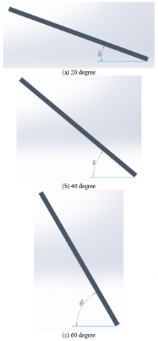
The experiments for this paper were performed using computational fluid dynamics for inclined fluidized bed. Three values of inclination angle were used (20°, 40°, 60°) (Figure 1). The fluidized bed used is a two-phase solid particles and water, the solid particles have (2803 kg/m3) density and 3.5 mm diameter. Different values of water velocity were examined (0.01, 0.03, 0.05, 0.1, 0.3 m/s), with different values of solid particles initial height (3.5, 5, 7.5, 10, 15 cm). SolidWorks 2018 program was used to model the geometry of the duct numerically, using two-dimensional models. The mesh was generated with Ansys 15.0, Quadrilateral mesh was used. Figure 2 shows the mesh of the duct, with size equal to (0.002 m) which gave (7500) elements and (8016) nodes. Fluent attached with Ansys 15.0 was used to simulate the behavior of the duct. Eulerian multiphase model was used along with k-epsilon turbulent model for the two-phase air water flow. Pressure based transient simulation was performed. Under relaxation factor used for the models is presented in Table 1.
Figure 1. Geometries created with SolidWorks
Figure 2. Close look for the mesh
Table 1. Under relaxation factor
|
Pressure |
Momentum |
Other factors |
|
0.3 |
0.7 |
1 |
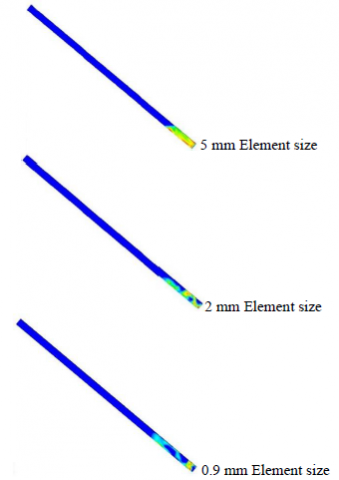
The mesh element size used in these simulations was validated by testing three different sizes, course, medium and fine. For course mesh (5 mm) selected as the size of elements, (2 mm) was selected as the size of element for medium mesh, whereas for fine mesh (0.9 mm) was selected as the size of elements. The three meshed models were simulated for the same fluidized bed at the same boundary and initial conditions. The results showed that the most suitable size of meshing element to use is (2mm); Figure 3 shows a comparison among the results.
Figure 3. Mesh validation results comparison
2.2 Boundary conditions
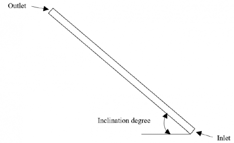
Boundary conditions used for the simulation is the water velocity enters at its highest value from the bottom of the duct with ambient initial temperature. The outlet was set as outlet pressure (Figure 4).
Figure 4. Boundary conditions
2.3 Governing equations for the models used
The Eulerian model was used in this work to represent the flow of water and solid particles distribution in the ribbed duct. The Eulerian model solves the equations of continuity, momentum and energy for mixture (Fluent User’s Guide 2006) [26, 27].
I- Mass conservation equation
The following equation represented the Mass conservation
$\frac{\partial }{\partial t}({{\alpha }_{q}}{{\rho }_{q}})+\nabla .({{\alpha }_{q}}{{\rho }_{q}}\overrightarrow{{{v}_{q}}})=\sum\limits_{p=1}^{n}{({{\overset{.}{\mathop m}\,}_{pq}}-{{\overset{.}{\mathop m}\,}_{qp}})+{{S}_{q}}}$ (1)
II- Momentum conservation equation
The general form for this equation is as Eq. (2).
$\begin{align} & \frac{\partial }{\partial t}({{\alpha }_{q}}{{\rho }_{q}}\overrightarrow{{{v}_{q}}})+\nabla .({{\alpha }_{q}}{{\rho }_{q}}\overrightarrow{{{v}_{q}}}\overrightarrow{{{v}_{q}}})=-{{\alpha }_{q}}\nabla p+\nabla .{{\overline{\overline{\tau }}}_{q}}+{{\alpha }_{q}}{{\rho }_{q}}\overrightarrow{g} \\ & +\sum\limits_{p=1}^{n}{({{\overrightarrow{R}}_{pq}}+{{\overset{.}{\mathop{m}}\,}_{pq}}{{\overrightarrow{v}}_{pq}}-{{\overset{.}{\mathop{m}}\,}_{qp}}{{\overrightarrow{v}}_{qp}})}+({{\overrightarrow{F}}_{q}}+{{\overrightarrow{F}}_{lift,q}}+{{\overrightarrow{F}}_{vm,q}}) \\\end{align}$ (2)
III- Turbulent model equations
The turbulent model used for this computational study is k-epsilon with RNG mixture model. The general equations for this model are as Eqns. (3) and (4).
$\frac{\partial }{\partial t}\left( {{\rho }_{m}}k \right)+\nabla .\left( {{\rho }_{m}}{{{\vec{v}}}_{m}}k \right)=\nabla .\left( \frac{{{\mu }_{t,m}}}{\sigma k}\nabla k \right)+{{G}_{k,m}}-{{\rho }_{m}}\in $ (3)
$\begin{align} & \frac{\partial }{\partial t}\left( {{\rho }_{m}}\in \right)+\nabla .\left( {{\rho }_{m}}{{{\vec{v}}}_{m}}\in \right)=\nabla .\left( \frac{{{\mu }_{t,m}}}{{{\sigma }_{\in }}}\nabla \in \right) \\ & +\frac{\in }{k}({{C}_{1\in }}{{G}_{k,m}}-{{C}_{2\in }}{{\rho }_{m}}\in \\\end{align}$ (4)
2.4 Validation of the numerical model
The model was validated using an experimental research by Yakubov et al. Figure 5 shows comparison between the experimental results of the paper and the results from the computational fluid dynamics model that was developed for this research. Four values of inclination angle degree were investigated (20, 40, 60, and 70). Figure 5 shows the effect of fluid flow rate on the fluidization height compared to the initial height of the solid particles. A good agreement between the experimental and numerical results have found as it shown in the figure.
Figure 5. Validation of the numerical model
3.1 The Influence of water velocity on the bed expansion
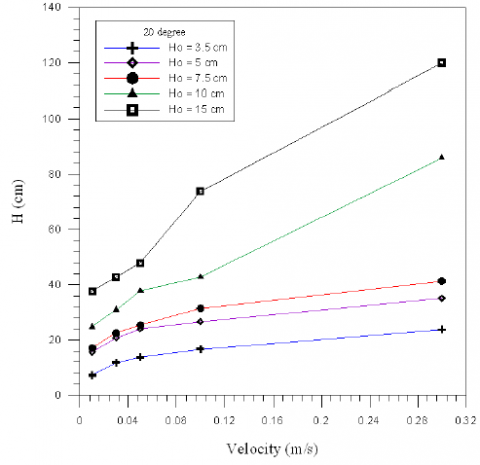
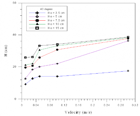
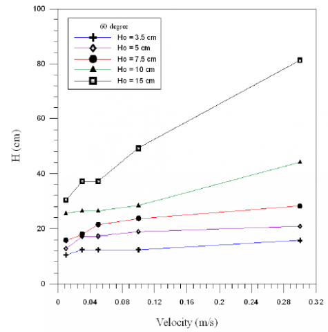
Figures 6a 6b and 6c show the solid particles expansion inside the fluidized bed numerically with water velocity for five varied values of initial height bed at constant values of fluidized bed's angle. As velocity of water increased, the upgrading of solid particles inside the pipe increased over the value that originally required into the bed as well as the spaces between the particles increased. The increase that happened in the elevation of solid particles was due to the increase in the amount of water pushed into the pipe as the water velocity increased which pushed the particles into beyond places within the column.
Figure 6a. Relationship between velocity and fluidized bed height at angle = 20°
Figure 6b. Relationship between velocity and fluidized bed height at angle = 40°
Figure 6c. Relationship between velocity and fluidized bed height at angle = 60°
3.2 The Influence of fluidized bed inclination on the bed expansion
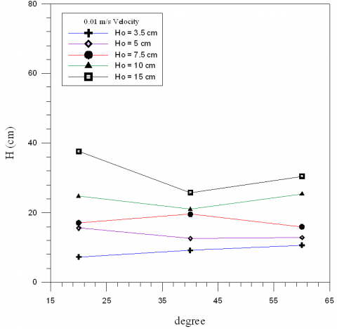
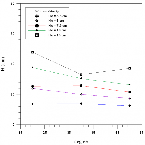
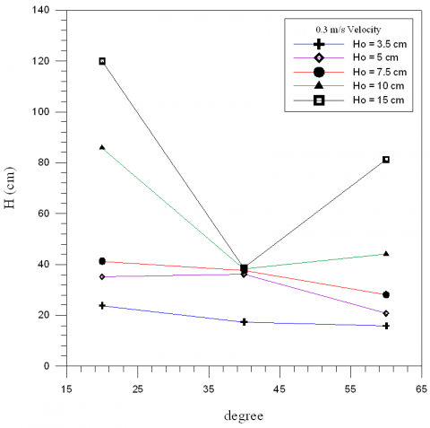
Figures (7a, 7b, 7c, 7d) show the effect of fluidized bed's inclination angle on the bed expansion at five different initial height of particles in the pipe HO (3.5, 5, 7.5, 10, 15 cm) and for four different velocity (0.01, 0.03, 0.05, 0.3 m/s) for each figures respectively. First, it is observed that for all figures, the bed expansion reaches maximum value at inclination of about 20°. This is because the pushing force of air that represent by velocity, when increase the velocity, this leads to increase in bed expansion especially at velocity 0.3m/s. At inclination 40°, the bed expansion is lower than at angle 20°, because lack the influence of angle on the expansion of particles but this influence increase when increase initial bed height.
Figure 7a. Relationship between bed's inclination angle and fluidized bed height at velocity 0.01m/s
Figure 7b. Relationship between bed's inclination angle and fluidized bed height at velocity 0.03m/s
Figure 7c. Relationship between bed's inclination angle and fluidized bed height at velocity 0.05m/s
Figure 7d. Relationship between bed's inclination angle and fluidized bed height at velocity 0.3m/s
At inclination 60°, the bed expansion is more than at angle 40°, because the lift force in the inclined tubes increase do to force of the lateral gravitation, because of this force the particles are directed to the pipe wall where the water velocity is low and limited. Therefore, the particles are moved in the pipe in a circular motion and to transfer these particles away from the bed bottom a large water flow rate is required. Figures (7c, 7d) shows that for 3.5 cm initial height of solid particles, as the velocity increases its influence on the height of the bed decreases as well as the inclination angle due to the small initial height of solid particles compared to the other studied cases which makes it a packed bed more than a fluidized bed.
3.3 Effect of water superficial velocity on the solid volume fraction
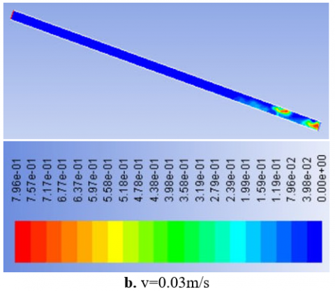
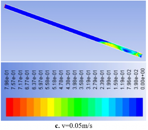
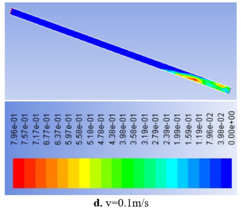
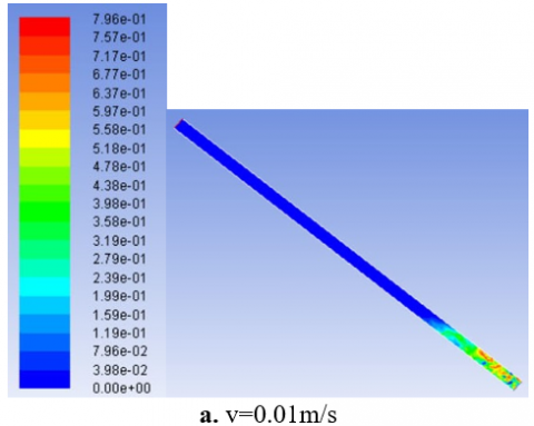
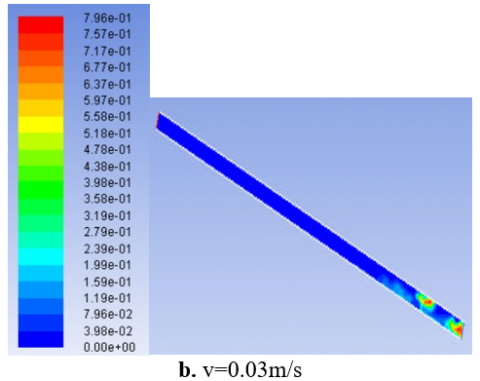
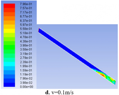
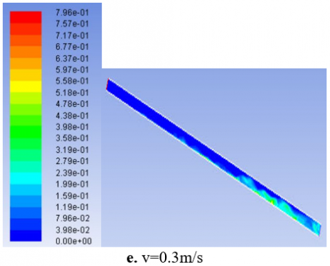
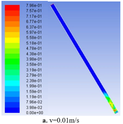
Contours of volume fraction of bed of fluidization at different water velocities (0.01 0.03 0.05 0.1 0.3) m/s, with degree of inclined 200 and initial bed height (5) cm, shown in Figures (8a, 8b, 8c, 8d, 8e). At the velocity of 0.01m/s the bed began to expand as water began to rush upward, the bed height increases with velocity of water increase until reach to maximum at velocity 0.3m/s. The reason attributed when water velocity increases the spaces between the solid particles increase as the expansion of the solid particles increased, so the solid particles slide down along the wall of the bed without too much resistance from the upward water flow. Also, the inclined of bed helps increase water flow in the tube compared to the vertical tube.
Contours of volume fraction of bed of fluidization at different water velocities (0.01, 0.03, 0.05, 0.1, 0.3) m/s, with degree of inclined 40° and initial bed height (10) cm, shown in Figure (9a, 9b, 9c, 9d, 9e). From the figures it can be seen that the velocity of water is higher in the part of the bed where no particles are transformed, this is because the particles obstruct the flow of water. At the velocity of 0.01m/s the bed began to expand and the liquid implement through the solids so the solids move in circulating way and move away from bed's base, at the velocity of 0.03m/s the particles began aggregate because the increase in velocity.
In velocity 0.05 and 0.1 m /s, the particles blend with liquid and become the solution. For velocity 0.3m/s and because the increase in velocity the solution reach to a maximum point as possible as and is inclined toward the wall because the inclined of bed.
Contours of volume fraction of bed of fluidization at different water velocities (0.01, 0.03, 0.05, 0.1, 0.3) m/s, with degree of inclined 60° and initial bed height (7.5) cm, shown in Figures (10a, 10b, 10c, 10d, 10e). Because the increase in inclined of bed compare with the previous beds and be near to vertical, the particles mixing with water in low velocities 0.01 and 0.03 m/s. In v = 0.05 and 0.1 m/s the solution wrought began rise in bed with agglomeration in particles. However, in increase in velocity 0.3 m/s the solution rush to end of particles as possible as it can.
Figures 8(a-e). The images of effect of water superficial velocity on the solid volume fraction at degree of inclined 20° and HO (5) cm
Figures 9(a-e). The images of effect of water superficial velocity on the solid volume fraction at degree of inclined 40° and HO (10) cm
Figures 10(a-e). The images of effect of water superficial velocity on the solid volume fraction at degree of inclined 60° and HO (7.5) cm
In this paper, the fluidized bed was studied in inclined position. Different values of inclination degrees were used, as well as the water velocity and the height of the solid particles initially placed in the bed. The study was performed numerically using CFD and the model was validated with results from other experimental paper. It was found that:
1. As velocity of water increased, the upgrading of solid particles inside the pipe increased.
2. The expansion of solid particles decreased as the inclination degree of pipe increased.
|
A |
Volume fraction |
|
|
B |
dimensionless heat source length |
|
|
CP |
Specific heat, J. kg-1. K-1 |
|
|
D |
Diameter (m) |
|
|
E |
Rib height (m) |
|
|
F |
Force (N) |
|
|
g k |
gravitational acceleration, m.s-2 Thermal conductivity, W.m-1. K-1 |
|
|
h |
Heat transfer coefficient (w/m2.K) |
|
|
Nu |
local Nusselt number along the heat source |
|
|
Pr |
Prandtl number (µ Cp/k) |
|
|
Re |
Reynolds number (ρ u D/µ) |
|
|
T |
Temperature (K) |
|
|
v |
Velocity (m/s) |
|
|
w |
Duct width (m) |
|
|
Greek symbols |
|
|
|
$\alpha$ |
thermal diffusivity, m2. s-1 |
|
|
$\beta$ |
thermal expansion coefficient, K-1 |
|
|
$\phi$ |
solid volume fraction |
|
|
Ɵ |
dimensionless temperature |
|
|
µ |
Dynamic viscosity, kg. m-1. s-1 |
|
[1] Davarnejad, R., Eshghipour, R., Abdi, J., Dehkordi, F.B. (2014). CFD Modeling of a binary liquid-solid fluidized bed. Middle-East Journal of Scientific Research, 19(10): 1272-1279. https://doi.org/10.5829/idosi.mejsr.2014.19.10.89
[2] Reddy, R.K., Joshi, J.B. (2009). CFD modeling of solid–liquid fluidized beds of mono and binary particle mixtures. Chemical Engineering Science, 64(16): 3641-3658. https://doi.org/10.1016/j.ces.2009.05.004
[3] Fan, L., Gracey, J., Epsteinz, N. (2010). CFD Simulation of a liquid-fluidized bed of binary paricles. 13th International Conference on Fluidization - New Paradigm in Fluidization Engineering.
[4] Tabrizi, H.B., Panahandeh, M., Saidi, M. (2013). Experimental Segregation of Binary Particles using Gas-Solid Fluidized Bed. Proceedings of the World Congress on Engineering, 3.
[5] Khan, M.J.H., Hussain, M.A., Mansourpour, Z., Mostoufi, N., Ghasem, N.M., Abdullah, E.C. (2014). CFD simulation of fluidized bed reactors for polyolefin production-A review. Journal of Industrial and Engineering Chemistry, 20(6): 3919-3946. https://doi.org/10.1016/j.jiec.2014.01.044
[6] Lu, H.L., He, Y.R., Gidaspow, D., Yang, L.D., Qin, Y.K. (2003). Size segregation of binary mixture of solids in bubbling fluidized beds. Powder Technology, 134: 86–97. https://doi.org/10.1016/S0032-5910(03)00126-8
[7] Nguyen, K.T., Huang, S.C. (2011). Simulation of Hydrodynamic Characteristics of Glass Beads in Gas-Liquid-Solid Three Phase Fluidized Beds by Computational Fluid Dynamics. Journal of Engineering Technology and Education, 8 (2): 248-261.
[8] Al-Turaihi, R.S., Oleiwi, S.H. (2015). Experimental and CFD investigation the effect of solid particle height in water-solid flow in fluidized bed column. International Journal of Mechanical Engineering and Applications, 3(3): 37-45. https://doi.org/10.11648/j.ijmea.20150303.12
[9] Kumar, M.M., Natarajan, E. (2009). CFD simulation for two-phase mixing in 2D fluidized bed. Int J Adv Manuf Technol, https://doi.org/10.1007/s00170-008-1875-9
[10] Jena, H.M., Roy, G.K., Biswal, K.C. (2008). Studies on pressure drop and minimum fluidization velocity of gas-solid fluidization of homogeneous well mixed ternary mixtures in Un-promoted and promoted square bed. Chemical Engineering Journal, 145(1): 16-24. https://doi.org/10.1016/j.cej.2008.02.013
[11] Stanly, R., Shoev, G., Kokhanchik A.A. (2017). Numerical simulation of gas-solid flows in fluidized bed with TFM model. AIP Conference Proceedings, 1893(1). https://doi.org/10.1063/1.5007498
[12] Wu, K., de Martín, L., Mazzei, L., Coppens, M. (2016). Pattern formation in fluidized beds as a tool for model validation: A two-fluid model based study. Powder Technology, 295: 35-42. https://doi.org/10.1016/j.powtec.2016.03.011
[13] Wang, L., Xie, X., Guangchao, W., Li, R. (2017). Numerical simulation of hydrodynamic characteristics in a gas–solid fluidized bed. Particulate Science and Technology an International Journal, 35(2). https://doi.org/10.1080/02726351.2016.1146809
[14] Lianga, J.D., Hsua, C.Y., Hunga, T.C., Chiangb, Y.C., Chena, S.L. (2018). Geometrical parameters analysis of improved circulating inclined fluidized beds for general HVAC duct systems. Applied Energy, 230: 784-793. https://doi.org/10.1016/j.apenergy.2018.09.003
[15] Nakamura, H., Kondo, T., Watano, S. (2013). Improvement of particle mixing and fluidization quality in rotating fluidized bed by inclined injection of fluidizing air. Chemical Engineering Science, 91: 70-78. https://doi.org/10.1016/j.ces.2013.01.022
[16] O’Dea, D.P., Rudolph, V., Chong, Y.O. (1990). The effect of inclination on fluidized beds. Powder Technology, 63: 169-178. https://doi.org/10.1016/0032-5910(90)80039-2
[17] Sarkar, M., Gupta, S.K., Sarkar, M.K. (1991). An experimental investigation of the flow of solids from a fluidized bed through an inclined pipe. Powder Technology, 64(3): 221-231. https://doi.org/10.1016/0032-5910(91)80137-8
[18] Hudson, C., Briens, C.L., Prakash, A. (1996). Effect of inclination on liquid-solid fluidized beds. Powder Technology, 89(2): 10l-113. https://doi.org/10.1016/S0032-5910(96)03153-1
[19] Cai, R., Gu, C., Li, Y.Z.Q., Meng, A. (2015). Effect of inclined distributor on the motion behavior of a large spherical object in the bottom zone of a fluidized bed. Powder Technology, 277: 147-155. https://doi.org/10.1016/j.powtec.2015.02.058
[20] Qi, X.Q., Li, Y.F., Li, N.B., Zhang, W.J., Xia, W.C., Li, Y., Zhu, R.T. (2017). Influence of inclined channels on the critical motion of particulate suspensions in a liquid-solid fluidized bed. Powder Technology, 318: 306-313. https://doi.org/10.1016/j.powtec.2017.05.045
[21] Hamed, A.M. (2005). Experimental investigation on the adsorption/desorption processes using solid desiccant in an inclined-fluidized bed. Renewable Energy, 30(12): 1913-1921. https://doi.org/10.1016/j.renene.2005.01.001https://doi.org/10.1016/j.renene.2005.01.001
[22] Yakubov, B., Tanny, J., Marona, D.M., Brauner, N. (2007). The dynamics and structure of a liquid–solid fluidized bed in inclined pipes. Chemical Engineering Journal, 128(2-3): 105-114. https://doi.org/10.1016/j.cej.2006.10.020.
[23] Callen, A., Moghtaderi, B., Galvin, K.P. (2007). Use of parallel inclined plates to control elutriation from a gas fluidized bed. Chemical Engineering Science, 62(1-2): 356-370. https://doi.org/10.1016/j.ces.2006.08.057
[24] Fu, Y., Chen, W., Su, D., Lv, B., Luo, Z. (2019). Spatial characteristics of fluidization and separation in a gas-solid dense-phase fluidized bed. Powder Technology, 362: 246-256. https://doi.org/10.1016/j.powtec.2019.11.065.
[25] Wu, G., Chen, W., He, Y. (2020). Investigation on gas–solid flow behavior in a multistage fluidized bed by using numerical simulation. Powder Technology, 364: 251-263. https://doi.org/10.1016/j.powtec.2020.01.078
[26] Chapter 23. Modeling Multiphase Flows. c Fluent Inc. September 29, 2006.
[27] Tutorial: Modeling Uniform Fluidization in 2D Fluidized Bed. c Fluent Inc. May 16, 2002.