Mebrouk Benbrika* | Mohamed Teggar | Mohamed Benbelhout | Kamal Abdel Radi Ismail
© 2020. IIETA. This article is published by IIETA and is licensed under the CC BY 4.0 license (http://creativecommons.org/licenses/by/4.0/).
OPEN ACCESS
This paper investigates numerically the melting of n-eicosane inside horizontal cylinders. The cylinders are embedded in a storage tank where hot air flows parallel to the cylinders during the charging process. The 2D mathematical model is based on the enthalpy-porosity method. To solve the conservation equations (continuity, momentum and energy), a CFD commercial software is employed. Numerical predictions are validated by comparison with benchmark results available in the literature. The melting characteristics of n-eicosane in horizontal cylinders are presented. The phase change dynamics, temperature distributions and melt flow patterns are analyzed. The effect of heating rate is investigated. Results show that after certain time natural heat convective currents have not the same positive effect on the melting rate due to the continuous heating of the upper melt in the enclosure; which contributes to lower the thermal charging time. Low heating rate (h=25 W m-2 K) intensifies this negative effect.
latent heat, melting, N-eicosane, PCM, thermal storage
Melting control of Phase Change Materials (PCMs) is essential for the design of efficient latent heat storage systems. Encapsulated PCMs are widely used in thermal accumulators in domestic solar air/water heating systems.
Liquid-solid phase change inside enclosures attracted researcher’s attention for decades. Saraf and Sharif [1] conducted a numerical study on freezing of water in cylinders. Braga et al. [2] studied solidification of water in cylindrical enclosures. Parameters affecting phase change such as the coolant temperature, the capsule material and its diameter were investigated.
Latent heat storage systems encountered in practice can be classified as pipe model; shell and tube or embedded tubes in a cylindrical shell [3]. Many research works were carried out on these system configurations. Essen et al. [4] conducted a study on two different latent heat storage systems (pipe and shell and tubes types). The authors investigated the effect of some parameters affecting the performance of the two systems such as type of PCM, cylinder dimension, mass flow rate of the working fluid and its inlet temperature. Agyenim et al. [5, 6] carried out an experimental study on a shell and tube module. They concluded that thermal conduction in the axial direction of the system can be neglected. The authors reported also that temperature gradients in the axial direction of the pipes were less than 5%. In shell and tube storage systems, the working fluid can be introduced from different cylinder ends. These alternatives and their thermal effect were studied numerically by Gong and Mujumdar [7]. The problem of solidification of different PCMs (water and water mixtures) was investigated by Ismail and Moraes [8]. The materials were encapsulated in different containers (spheres and cylinders) embedded in a thermal storage system. The time required for the total solidification was particularly investigated. De Gracia et al. [9] studied the effect of Biot number on heat transfer characteristics of a PCM inside PVC cylinders in a heat storage tank. Teggar et al. [10] investigated the effect of non-dimensional thermal parameters on heat transfer and phase change of unfixed PCM in circular cylinders. The authors reported that at the earlier stages of PCM solidification the extracted heat rate at the enclosure surface increases with increasing Biot number. But, later the increase in Biot number leads to lower heat rate.
Natural convection has a strong effect on the melting process in enclosures. Therefore, understanding these convective heat transfer features is necessary for enhancement of latent thermal storage systems. The onset of natural convection during melting of n-octadecane in a horizontal cylinder was studied experimentally by Azad et al. [11]. The effect of different heating temperatures was investigated. Hlimi et al. [12] presented a numerical study of natural convection during melting of Gallium inside a horizontal cylinder. The effect of Rayleigh number on liquid flow and heat transfer characteristics was investigated.
Design of effective latent heat storage devices incorporating circular enclosures requires control of melting process and its features. This study is aimed to analyze the melting process of n-eicosane in horizontal cylinders. Heat transfer and melt flow patterns in the cylinders are particularly investigated for different heating rates. Results show that convective currents have not always an accelerating effect of the melting rate.
2.1. Physical model
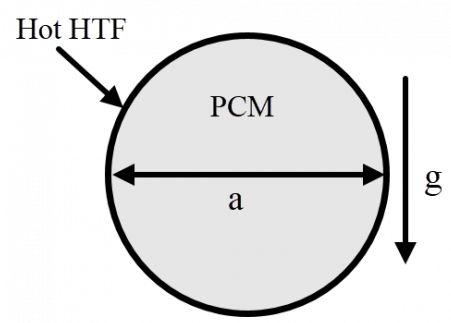
Consider a horizontal cylinder of 4 cm diameter. The cylinder is filled with PCM (n-eicosane) whose thermophysical properties are shown in Table 1. Unfixed working fluid flows over the cylinder (parallel to it). The melting process can be approximated by a 2D problem (Figure 1) since the axial heat transfer can be neglected on a given axial portion. The PCM is initially solid at Ti=290.15 K. The outer surface of the cylinder is subject to convective heat flux (mean convection heat transfer coefficient h). The mathematical model describing melting process is based upon the following assumptions: (i) Flow in the melt region is assumed to be laminar, unsteady and incompressible. (ii) Boussinesq approximation is employed in the buoyancy term. (iii) Viscous dissipation is neglected.
Table 1. Thermophysical properties of N-eicosane.
|
Properties |
Values |
|
Melting temperature |
308.15 – 310.15 K |
|
Density ( $\rho_{0}$ ) |
770 kg m-3 |
|
Kinematic viscosity ( v ) |
5x10⁻⁶ m2 s-1 |
|
Specific heat ( $C_{p}$ ) |
2.460 kJ kg-1 K-1 |
|
Thermal conductivity ( k ) |
0.1505 W m-1 K-1 |
|
Latent heat of fusion ( $L_{f}$) |
247.6 kJ kg-1 |
|
Thermal expansion coefficient ($\beta$ ) |
0.0009 K-1 |
Figure 1. Sketch of the 2D melting problem
2.2 Mathematical modeling
Modeling heat transfer during 2D inward melting of n-eicosane is done by using the enthalpy-porosity method. The incompressible viscous flow and heat transfer are described by the following conservation equations:
Mass
$\frac{\partial \rho}{\partial t}+\nabla \cdot(\rho \vec{\vartheta})=0$ (1)
Momentum
$\frac{\partial}{\partial t}(\rho \vec{\vartheta})+\nabla \cdot(\rho \vec{\vartheta} \vec{\vartheta})=-\nabla p+\nabla \cdot(\mu \nabla \vec{\vartheta})+\rho \vec{g}+\vec{S}$ (2)
Energy
$\frac{\partial}{\partial t}(\rho \mathrm{H})+\nabla \cdot(\rho \vec{\vartheta} \mathrm{H})=\nabla \cdot(\mathrm{k} \nabla \mathrm{T})$ (3)
$\overrightarrow{\mathrm{S}}$ in Eq. (2) is defined as a source term (Darcy’s law) to account for phase change in the momentum equation.
Enthalpy that appears in Eq. (3) is defined as follows.
$\mathrm{H}=\mathrm{h}+\Delta \mathrm{H}$ (4)
With
$\Delta \mathrm{H}=\lambda \mathrm{L}$ (5)
where, $\lambda$ is the liquid fraction defined by:
$\lambda=\left\{\begin{array}{ll}0 & \text { If } \mathrm{T} \leq \mathrm{T}_{5} \\ 1 & \text { If } \mathrm{T} \geq \mathrm{T}_{1} \\ \frac{\mathrm{T}-\mathrm{T}_{5}}{\mathrm{T}_{1}-\mathrm{T}_{\mathrm{s}}} \text { if } & \mathrm{T}_{\mathrm{s}}<\mathrm{T}<\mathrm{T}_{1}\end{array}\right.$ (6)
The following boundary conditions are imposed:
The centerline of the cylinder:
$\mathrm{u}=0 ; \vartheta=0 ; \frac{\partial \mathrm{T}}{\partial \mathrm{r}}=0$ (7)
The cylinder wall
$\mathrm{u}=\vartheta=0 ; \frac{\partial \mathrm{T}}{\partial \mathrm{r}}=\mathrm{h}\left(\mathrm{T}_{\mathrm{HTF}}-\mathrm{T}_{\mathrm{w}}\right)$ (8)
2.3 Numerical procedure
Numerical resolution of the mathematical model was realized by using a CFD code. The QUICK scheme was used for special discretization. The SIMPLE algorithm was employed for the velocity-pressure coupling. While for pressure equations correction, the PRESTO scheme was used. Relaxation factors used were 0.3, 0.7, 1 and 0.9 respectively for the pressure, the velocity, the energy and the liquid fraction. Residual convergence values were chosen $10^{-3}, 10^{-3}$ and $10^{-6}$ respectively for the continuity, momentum and energy equations. Different grid sizes were tested to ensure grid independency of the numerical predictions. The tests were done on the liquid fraction as function of time. The optimum choice was 10577 unstructured finite volume grids (Figure 2). For the time step the test results showed that 0.1 s was an optimum choice (Figure 3).
Figure 2. Mesh dependency of the numerical predictions
Figure 3. Time step optimization for the present model
2.4 Validation
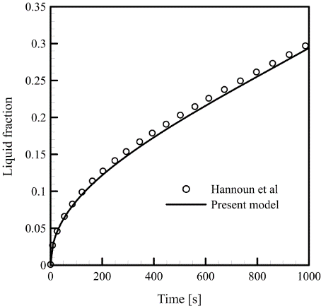
The numerical predictions of the present code have been validated by comparison with the benchmark results presented by Hannoun et al. [13]. The authors studied melting of tin in a square cavity (0.1x0.1 m2). The thermophysical properties of tin are [13]: melting temperature 505 K, density 7500 kg m-3, kinematic viscosity 5x10⁻⁷ m2 s-1, specific heat 200 J kg-1 K-1, thermal conductivity 60 W m-1 K-1, latent heat of fusion 247.6 kJ kg-1 and thermal expansion 2.67 10-4 K-1. Tin was initially solid at the melting temperature Tf=505 K. One vertical wall of the cavity was heated to a temperature above the melting point (508 K). The horizontal walls were maintained adiabatic. Comparison of the two results is based upon the time evolution of the liquid fraction in the cavity. Good agreement between the two results was obtained as can be seen in Figure 4.
Figure 4. Comparison of predictions (liquid fraction versus time) of the present model and numerical results due to Hannoun et al. [13]
In this section, the characteristics of n-eicosane melting in a horizontal cylinder for different thermal heating rates are analyzed. The analysis includes the temperature distributions, liquid fractions, melt streamlines, liquid fraction evolution and the time for complete melting. The external surface of the cylinders is subjected to convective heat flux with an average heat convection coefficient (h). The HTF temperature is kept constant at T = 325 K.
3.1 Temperature distribution
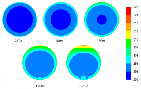
Figure 5 shows the temperature distribution in the cylinder at five different time instants (250, 500, 750, 1000 and 1250 s) for h=100 W.m-2.K-1. At the beginning of the melting process, the temperature distribution is concentric; isotherms have the shape of the heated cylinder wall. At this stage heat transfer is mainly by conduction. However, this behavior was observed in previous works in the literature [12-17].
The concentric isotherms are distorted with time; this distortion is due to the convective heat currents provoked by the buoyancy force. The isotherms distortion is seen at 1000 s for the high heating rate (h=100 W.m-2.K-1) but the distortion in the low rate, i.e. h=25 W.m-2.K-1, is observed earlier at 500 s as can be seen in Figure 6. Therefore, the onset of buoyancy driven convection is first initiated at low thermal loading. Moreover, temperatures are higher in the upper region of the cylinder as time evolves; which means that some of the absorbed thermal energy is used for heating the melt above the solid PCM. This heating effect is more pronounced in the case of lower heating rate. Higher temperatures than those of high thermal loading are observed.
Figure 5. Temperature distribution at different times for h=100 W.m-2.K-1
Figure 6. Temperature distribution at different times for h=25 W.m-2.K-1
At time 1250 s, stratified temperatures are seen in the liquid layer in the upper part of the cylinder. This thick melted layer increases the thermal resistance in the upper region of the cylinder which leads to decreasing the melting rate on the upper solid surface.
3.2 Liquid fraction status and melt streamlines
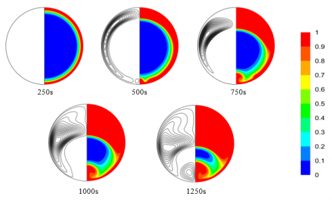
The liquid fractions and the streamlines into the cylinder at different time intervals in the case of h=100 W m-2 K-1are presented in Figure 7. The melt fractions are illustrated on the right hand half section of the cylinder while the patterns of the melt flow are illustrated in the left hand half section.
Figure 7. Melting front (right) and streamlines (left) at different times for h=100 W.m-2.K-1
At the beginning of the melting process (250 s), a thin layer of liquid PCM is symmetrically formed between the heated cylinder wall and the solid PCM undergoing phase change, the molten layer is concentric. This thin layer is not sufficient for development of natural convection currents. Thus, heat transfer is dominated by conduction as mentioned above.
However, in small volumes natural convection can be ignored as indicated by earlier works of melting/solidification problems [18-20]. Recently, Yang et al. [21] showed that there is a considerable difference in time of complete melting of PCM in a shell and tube system. The melting time values estimated by two models (conduction-based and convection-based models) showed that the predicted melting time is enhanced by a factor of 1.74 when the convection model was used.
At time 500 s, the molten layer becomes thicker in the upper half of the cylinder. The melting progress is seen to be better on the upper region of the enclosure compared to the bottom region. Due to the buoyancy effect, heat transfer is enhanced in the region above the solid PCM. Most of the absorbed heat is transported by natural convection to the top of the enclosure. In addition, the PCM solid surface exposed to the hot melt diminishes with time.
As time proceeds (750 s), while the upper phase change front in the enclosure has still a curved shape, the two small counter-rotating vortices alter the melting front in the bottom of the cylinder.
However, when the solid density is more than that of the liquid PCM, the solid core moves downward during the melting process driven by the gravity force (sink effect). This effect is investigated in previous studies [22-27]. But, when there is no significant difference in the density, as in the present case, the solid core does not sink and the liquid is constrained.
The streamlines are symmetrical about the vertical plan of the cylinder (Figure 7).
At time 500 s, two large counter-rotating vortices are formed causing the upward movement of the hot melt. At time 750, for the high heating rate, two additional vortices characterize the flow pattern. Stronger natural convection can be seen for high heating rate. Meanwhile, the flow for the lower heating rate (Figure 8) is dominated by two large vortices. The vortices appear at the bottom of the enclosure only at the final stages of the melting process (1250). At this time heat convection is significant in the middle of the enclosure. Weak convection is however observed in the upper region.
At time 1000 s, the vortices become larger; more PCM is then melted. The upper vortices’ centers are slightly shifted downward towards the bottom.
Figure 8. Melting front (right) and streamlines (left) at different times for h=25 W.m-2.K-1
3.3 Time evolution of liquid fraction
The time variation of the mean liquid fraction is shown in Figure 9. As reported in earlier works [28], typically the liquid/solid fraction (phase change front) evolves with time as square root function [29]. The melting rate is high at the earlier stages of the melting process since the heat exchange surface between the solid PCM and the melted layer is large and the thin PCM liquid layer offers a small thermal resistance. As time advances, the front melting surface diminishes, the amount of melt becomes larger and hence the heat absorbed is used for both melting the solid PCM and heating the upper melt. Consequently, the melting rate slows down.
Figure 9. Time evolution of the liquid fraction for h=100W.m-2.K-1
3.4 Time for complete melting
Finally, the total time required for melting of n-eicosane in the cylinder of 4 cm diameter is calculated for different external heating rates. Figure 10 shows the variation of the total melting time with the heat convection coefficient between the cylinder and the working fluid. Coefficient values ranged from 25 to 100 W m-2 K-1corresponding to a wide range of working fluid conditions. For lower values of the convection coefficient, the melting time decreases rapidly with the increasing coefficient values. But, for higher values melting time varies slightly with variation of the convection coefficient. This means that with liquids as working fluid the melting time is not significantly affected by the loading rate while for gaseous working fluids the melting time is strongly affected by the loading rate.
Figure 10. Total melting time vs external heat convection coefficient
Melting of n-eicosane in a cylinder has been analyzed numerically. Various heating rates have been considered. The following conclusions have been drawn.
At the earlier stages of the melting process, heat conduction dominates heat transfer. Increase of the molten layer with time causes increasing of thermal resistance but the onset of natural convection enhances heat transfer and therefore melting progress. Nevertheless, after certain time convective currents decrease the melting rate due to the continuous heating of the upper melt. This negative effect on melting rate is stronger at the low heating rate (h=25 W m-2 K-1).
At the later stage of the melting process, heat transfer in the upper melt is mainly done by conduction. Stratified temperatures together with thicker layer increase the thermal resistance in the upper region. The stratification is more pronounced at lower heating rate (h=25 W m-2 K-1). Finally, unlike liquids, for gaseous working fluids the melting time is strongly affected by the loading rate.
This work is supported by the Algerian Ministry of Higher Education and Scientific Research ((DGRSDT-MESRS) under the framework of a project PRFU (A11N01UN030120190003).
|
Cp |
Specific heat, J. K−1.kg−1 |
|
H |
Specific enthalpy, J.kg-1 |
|
h |
Convection coefficient, W.m-2.K-1 |
|
k |
Thermal conductivity, W.m-1 K-1 |
|
L |
Latent heat, J .kg−1 |
|
m |
Masse, kg |
|
S |
Source term |
|
T |
Temperature, K |
|
t |
Time, s |
|
V |
Velocity, ms-2 |
|
Greek symbols
|
|
|
µ |
Dynamic viscosity, Pa.s |
|
ρ |
Density, kg.m-3 |
|
λ |
Liquid fraction |
|
ν |
Kinematic viscosity, m2 s-1 |
|
Subscripts
|
|
|
i |
initial |
|
f |
Fusion |
|
l |
Liquid |
|
s |
Solid |
|
w |
Wall |
[1] Saraf, G.R., Sharif, L.K.A. (1987). Inward freezing of water in cylinders. International Journal of Refrigeration, 10(6): 342-348. https://doi.org/10.1016/0140-7007(87)90120-4.
[2] Braga, S.L., Guzmán, J.J.M., Pacheco, H.G.J. (2009). A study of cooling rate of the supercooled water inside of cylindrical capsules. International Journal of Refrigeration, 32(5): 953-959. https://doi.org/10.1016/j.ijrefrig.2008.10.014
[3] Agyenim, F., Hewitt, N., Eames, P., Smyth, M. (2010). A review of materials, heat transfer and phase change problem formulation for latent heat thermal energy storage systems (LHTESS). Renewable and Sustainable Energy Reviews, 14(2): 615-628. https://doi.org/10.1016/j.rser.2009.10.015
[4] Esen, M., Durmuş, A., Durmuş, A. (1998). Geometric design of solar-aided latent heat store depending on various parameters and phase change materials. Solar Energy, 62(1): 19-28. https://doi.org/10.1016/S0038-092X(97)00104-7
[5] Agyenim, F., Eames, P., Smyth, M. (2010). Heat transfer enhancement in medium temperature thermal energy storage system using a multitube heat transfer array. Renewable Energy, 35(1): 198-207. https://doi.org/10.1016/j.renene.2009.03.010
[6] Agyenim, F., Hewitt, N., Eames, P., Smyth, M. (2008). Numerical and experimental development of medium temperature thermal energy storage (Erythritol) system for the hot side of LiBr/H2O air conditioning applications. In World Renewable Energy Congress, 2008.
[7] Gong, Z.X., Mujumdar, A.S. (1997). Finite-element analysis of cyclic heat transfer in a shell-and-tube latent heat energy storage exchanger. Applied Thermal Engineering, 17(6): 583-591. https://doi.org/10.1016/S1359-4311(96)00054-3
[8] Ismail, K.A.R., Moraes, R.I.R. (2009). A numerical and experimental investigation of different containers and PCM options for cold storage modular units for domestic applications. International Journal of Heat and Mass Transfer, 52(19-20): 4195-4202. https://doi.org/10.1016/j.ijheatmasstransfer.2009.04.031
[9] De Gracia, A., Oró, E., Farid, M.M., Cabeza, L.F. (2011). Thermal analysis of including phase change material in a domestic hot water cylinder. Applied Thermal Engineering, 31(17-18): 3938-3945. https://doi.org/10.1016/j.applthermaleng.2011.07.043
[10] Teggar, M., Mezaache, E., Benchatti, A., Zeghmati, B. (2010). Comparative study of heat transfer during solidification of phase change materials inside three different capsules. International Journal of Heat and Technology, 28(2): 19-24. https://doi.org/10.18280/ijht.280204
[11] Azad, M., Dineshan, D., Groulx, D., Donaldson, A. (2016). Melting of Phase Change Materials in a cylindrical enclosure: Parameters influencing natural convection onset. In Proceedings of the 4th International Forum on Heat Transfer, IFHT2016, Sendai International Center, Sendai, Japan. pp. 2-4.
[12] Hlimi, M., Hamdaoui, S., Mahdaoui, M., Kousksou, T., Msaad, A.A., Jamil, A., El Bouardi, A. (2016). Melting inside a horizontal cylindrical capsule. Case Studies in Thermal Engineering, 8: 359-369. https://doi.org/10.1016/j.csite.2016.10.001
[13] Hannoun, N., Alexiades, V., Mai, T.Z. (2005). A reference solution for phase change with convection. International Journal for Numerical Methods in Fluids, 48(11): 1283-1308. https://doi.org/10.1002/fld.979
[14] Alawadhi, E.M., Bourisli, R.I. (2012). The role of natural convection and density variations in the solidification process of water in an annular enclosure. WIT Transactions on Engineering Sciences, 74: 441-451. https://doi.org/10.2495/AFM120391
[15] Yuan, X., Tavakkoli, F., Vafai, K. (2015). Analysis of natural convection in horizontal concentric annuli of varying inner shape. Numerical Heat Transfer, Part A: Applications, 68(11): 1155-1174. https://doi.org/10.1080/10407782.2015.1032016
[16] Zhu, Y.D., Shu, C., Qiu, J., Tani, J. (2004). Numerical simulation of natural convection between two elliptical cylinders using DQ method. International Journal of Heat and Mass Transfer, 47(4): 797-808. https://doi.org/10.1016/j.ijheatmasstransfer.2003.06.005
[17] Jourabian, M., Farhadi, M., Darzi, A.A.R. (2016). Heat transfer enhancement of PCM melting in 2D horizontal elliptical tube using metallic porous matrix. Theoretical and Computational Fluid Dynamics, 30(6): 579-603. https://doi.org/10.1007/s00162-016-0402-0
[18] Stewart Jr, W.E., Smith, K.L. (1987). Experimental inward solidification of initially superheated water in a cylinder. International Communications in Heat and Mass Transfer, 14(1): 21-31. https://doi.org/10.1016/0735-1933(87)90005-4
[19] Ismail, K.A., De Jesus, A.B. (2001). Parametric study of solidification of PCM around a cylinder for ice-bank applications. International Journal of Refrigeration, 24(8): 809-822. https://doi.org/10.1016/S0140-7007(00)00059-1
[20] Ismail, K.A., Lino, F.A., Da Silva, R.C., de Jesus, A.B., Paixao, L.C. (2014). Experimentally validated two dimensional numerical model for the solidification of PCM along a horizontal long tube. International Journal of Thermal Sciences, 75: 184-193. https://doi.org/10.1016/j.ijthermalsci.2013.08.008
[21] Yang, X., Lu, Z., Bai, Q., Zhang, Q., Jin, L., Yan, J. (2017). Thermal performance of a shell-and-tube latent heat thermal energy storage unit: Role of annular fins. Applied Energy, 202: 558-570. https://doi.org/10.1016/j.apenergy.2017.05.007
[22] Gong, M., Chen, W., Zhao, Y., Zhu, B., Sun, F. (2008). Analysis of contact melting around a horizontal elliptical cylinder heat source. Progress in Natural Science, 18(4): 441-446. https://doi.org/10.1016/j.pnsc.2007.10.010
[23] Chen, W.Z., Yang, Q.S., Dai, M.Q., Cheng, S.M. (1998). An analytical solution of the heat transfer process during contact melting of phase change material inside a horizontal elliptical tube. International Journal of Energy Research, 22(2): 131-140. https://doi.org/10.1002/(SICI)1099-114X(199802)22:2<131::AID-ER345>3.0.CO;2-3
[24] Kozak, Y., Ziskind, G. (2017). Novel enthalpy method for modeling of PCM melting accompanied by sinking of the solid phase. International Journal of Heat and Mass Transfer, 112: 568-586. https://doi.org/10.1016/j.ijheatmasstransfer.2017.04.088
[25] Fomin, S.A., Wilchinsky, A.V. (2002). Shape-factor effect on melting in an elliptic capsule. International Journal of Heat and Mass Transfer, 45(14): 3045-3054. https://doi.org/10.1016/S0017-9310(02)00018-2
[26] Pan, C., Charles, J., Vermaak, N., Romero, C., Neti, S., Zheng, Y., Bonner III, R. (2018). Experimental, numerical and analytic study of unconstrained melting in a vertical cylinder with a focus on mushy region effects. International Journal of Heat and Mass Transfer, 124: 1015-1024. https://doi.org/10.1016/j.ijheatmasstransfer.2018.04.009
[27] Faden, M., König-Haagen, A., Höhlein, S., Brüggemann, D. (2018). An implicit algorithm for melting and settling of phase change material inside macrocapsules. International Journal of Heat and Mass Transfer, 117: 757-767. https://doi.org/10.1016/j.ijheatmasstransfer.2017.10.033
[28] Ã-zisik, M.N., Özısık, M.N., Özışık, M. N. (1993). Heat Conduction. John Wiley & Sons.
[29] Lee, Y.F., Boley, B.A. (1973). Melting of an infinite solid with a spherical cavity. International Journal of Engineering Science, 11(12): 1277-1295. https://doi.org/10.1016/0020-7225(73)90102-X