Md. Jashim Uddin | Mohammad M. Rahman*
© 2020. IIETA. This article is published by IIETA and is licensed under the CC BY 4.0 license (http://creativecommons.org/licenses/by/4.0/).
OPEN ACCESS
This paper performs a comparative analysis of two-dimensional transient water-copper oxide nanofluid flow and heat transportation inside a right-, acute- and obtuse-angled triangular cavity in the presence of a magnetic field. The vertical and inclined walls of the enclosure are maintained at a constant low temperature whereas the base wall is heated by a uniform thermal condition. The finite element method is used to solve the principal equations of nanofluid within the cavities along with the wall conditions. The outcomes of the present problem for a specific case are verified by the standard published numerical results. For comparative analysis, the isotherms, streamlines, the heat transfer distribution, the average heat transfer rate on the heated wall and within the cavities for the several pertinent parameters of the problem are demonstrated. The result shows that the nanofluid filled obtuse-angled triangular cavity exhibits a higher heat transfer rate for the lower and moderate values of the thermal Rayleigh number whereas for the higher thermal Rayleigh number acute-angled triangular cavity shows better heat transfer performance than that of the other two cases analyzed in the present study. The presence of a magnetic field lessens the heat transfer rate in nanofluid applications. The magnetic field inclination angle controls the flow and heat transfer of nanofluid. Nanofluid flow shows insignificant effects of the friction in cavities compared to that of the base fluid.
nanofluid, nanoparticles, right-, acute-obtuse-angled triangular cavities, finite element solution, magnetic field, heat transfer
Flow analysis in nanofluid filled cavities is the promising investigations in manufacturing applications on account of its diverse use in real-life phenomena. In the preservation scheme and astrophysical thermal energy, nanofluid filled ducts or solar thermal collector are significant equipment for scientists to investigate the mechanisms, heat transfer enhancement and flow configurations. Also, searching a true shape of the nanofluid filled equipment is an interesting topic. The presence of magnetic field in various situations for controlling heat transfer is an imperative research field. There are extensive instructions on imposing a magnetic field on the nanofluid filled domain. For instance, it could be applied in developing crystals in liquids and metallic casting. Importantly, it may well be applied to control current within fusion reactors and mining of geothermal energy. Instead of conventional fluids, nanofluids are being used for the energy gain from the earth’s core. To comprehend the geothermal energy extraction process from the earth’s core, more investigations are needed. The cost analysis is also an important part of the experiments. Analyzing the problem mathematically and computer simulations of the physical designs can reduce the experimental cost.
Many notable computer-simulated and experimental research [1-4] on heat transportation within a conventional fluid-occupied square, triangular, annular and rectangular cavities. Considering the real design, there are numerous numerical and experimental research [1-15] on the triangular cavities. These studies are on different types of triangular cavities such as the right-angled, isosceles, equilateral, etc. to display heat transfer related results. Various types of thermal walls are considered from the practical perspective in these studies. The results are analyzed by using conventional fluids. The heat transportation increases and directs to the corner between the hypotenuse and heated base wall for the right-angled triangular cavities. The heat transfer decreases if the apex tilt of the triangular vessel decreases. The heat energy transportation is increased if the vertical and leaned boundaries of the trilateral enclosure are heated up isothermally as well as the lower boundary has been heated non-uniformly. The conduction occurs in the triangular cavities for lower Rayleigh number and convection happens for higher buoyancy parameter. The magnetic field parameters effect is significant within the isosceles triangular cavity than that of the other types of triangular cavities. The heat transportation surrounded by the hollow space is not the same for horizontally and vertically enacted magnetic fields. The mean Nusselt number is inversely proportional to the effects of the magnetic field parameter.
In many practical applications, higher heat transfer is required. Conventional fluid, for instance, engine oil, water, pump oil, ethylene glycol, acetone, and glycerol and so on cannot meet the necessity of heat transfer for the industrial requirements. To enhance the prerequisite heat transfer, the fluid having higher thermal conductivity can be an option. Mingling solid nanoparticles of higher conductivity with conventional fluid which is called nanofluid [16] is a pioneering tactic to heighten the conductibility of the mixture. Comparing to conventional fluids, this extraordinary kind of artificial fluid has significantly greater thermal properties especially, the thermal conductivity. The applications and prospectus of nanofluids are available in the literature such as Wong and Leon [17], Das et al. [18], Mahian et al. [19], Kakac and Pramuanjaroenkij [20], Das et al. [21] and Chandrasekar and Suresh [22]. Progress uses and thermal features of nanofluids are reconnoitered by Uddin et al. [23]. Novel correlations for thermophoresis and Brownian diffusion are further set in by them. There are voluminous outcomes on nanofluids in the various alignments of flow and thermal fields [24-34]. A few investigators are concerned about the stream dynamics of nanofluids in hollow spaces of triangular shape despite having wide uses in the engineering and technological sectors. The investigators are concerned about the nanofluids flow dynamics in the different shapes of triangular cavities such as right-angled triangular, isosceles and equilateral triangular cavities. Ghasemi and Aminossadati [31] have investigated the heat transfer enhancement for a right-angulate triangular enclosure containing water-alumina nanofluid. The effects of the downward and upward sliding boundaries were the foremost concern in their work. The result displays that the stronger streamlined circulation, as well as the higher heat transportation, occur for the downward sliding motion wall. Billah et al. [32] have studied the water-copper nanofluid occupied right-angled triangular enclosure accompanying no-slip and variable thermal boundary conditions. The mean heat transfer has been analyzed for the various appropriate parameters of the system. The heat transfer increment for particle loading is also analyzed in this study. Mahmoudi et al. [33] have studied the free convection of copper oxide-water nanofluid flow within a triangular enclosure in the presence of a hydro-magnetic field. They have considered six unlike heat source positions at the stem boundary of the vessel. The result shows that for enhancing heat transfer, the consequences of the heat sources, as well as the heat source positions, are noteworthy. Selimefendigil and Oztop [35] had analyzed the free and forced convection in a water-copper nano-mixture filled right-angled triangular enclosure. They have considered a heater on the vertical boundary of the enclosure and an adiabatic rotating cylinder inside the enclosure. They reported that for the intensification of the overall entropy propagation and revolving cylinder velocity, the mean heat transportation intensifies. Additionally, utilizing water base copper oxide nanofluid, the heat transfer augmentation inside a right-angled triangular vessel has been analyzed by Ghasemi and Aminossadati [36]. The result demonstrates that the Brownian motion of nanoparticle significantly enhances the heat transfer.
Yu et al. [37] have analyzed the heat transfer behaviors inside the isosceles triangular cavity where copper oxide nanosolids with water have been utilized. A uniform temperature distribution has been assumed at the bottom wall of the cavity. Surprisingly, unconventional results in heat transfer and flow behaviors have been noticed in their work where heat transfer shrinkages substantially with the increment of nanoparticle volume fraction in the conventional fluid. Conversely, Rahman et al. [38] have studied the isosceles triangular shaped cavity utilizing three distinct nanofluids inside. Their results show that the parameters of the problem along with the nanoparticle volume fraction significantly affect the thermal and flow fields. The heat transfer rate increases outstandingly as the local Grashof number and the nanoparticle volume fraction increase. Besides, Rahman et al. [39] have investigated the flow, thermal and concentration field inside a symmetric trilateral enclosure. They have considered the three types of wall settings at the lower base wall. Their result shows that the variable thermal boundary condition exhibits remarkably higher heat transfer.
Many researchers have been motivated to search for the optimal design of cavities for heat transfer [40]. The functioning of several types of heat exchangers, solar thermal collectors and electronics and electrical components can be quite improved by many augmentation techniques. The geometrical design is one of them. Cavities shape factor is significant in heat transfer application to obtain the optimal performances. As particle motion happens from one part of the body to other parts at a given temperature; the energy extraction depends on the equilibrium movement of the particles. Some of the portions of the geometry may not have optimal particles motion due to the geometrical design. In this context, the importance of investigations on the geometrical shape before applying them cannot be overlooked. Also, the temperature distribution in solar absorbers is important to find the optimal results. The temperature distributions depend on the enclosures’ shape and boundary conditions. However, better geometrical design with proper boundary conditions is crucial to obtain higher and accurate performances. The heat transfer analysis within various patterns of heat transfer mediums such as square, rectangular, right-angled triangular, isosceles triangular, etc. are investigated in the literature. However, the comparative studies on the mechanism and the performance of heat transfer between them has not been given much attention. Also, the fluid flow and heat transfer within right-angled and isosceles triangular cavities are investigated in the literature due to its potential application in heat transportation but the attention on the qualified study on the heat transfer presentations among them has not been specified. Comparative analysis regarding the use of nanofluid in different objects for advanced heat transfer in the industry allows a company to evaluate the appropriate chilling technologies and guess overall operation. In reply to this industrial need and reviewing the literature, it is exposed that there is a critical necessity to scrutinize the free convection transmission process inside three types of the enclosure such as a right-, acute, and obtuse-angled triangular cavities utilizing nanofluid. A comparative study among these three types of the enclosure is very much essential for the industrial and scientific communities to comprehend heat transmission acts. The copper oxide-water nanofluid is considered to analyze the results. The finite element method has applied to find the solution. The results are displayed in terms of isotherms and streamlines for the three types of cavities. The average and local Nusselt numbers for three types of cavities are also displayed to get a clear insight into the performances.
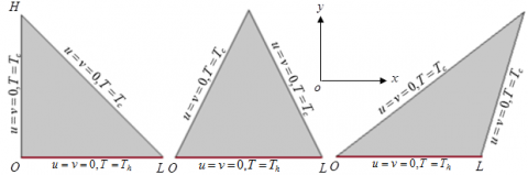
In the xy-Cartesian coordinates, the geometries are placed as in Figure 1. A right-angled triangular, an acute-angled triangular and an obtuse-angled triangular cavity are considered in the investigation. These three types of nanofluid filled cavities are well-thought-out from the literature reviews where many important applications on them are available. Copper oxide-water nanofluid is carefully weighed inside the cavities to distingue the performances. For instance, the right-angled and equilateral triangular cavities are used as the solar thermal collector in the solar panel. The sloped wall of the cavities is fixed as glass cover whereas the base wall of the cavities is heated. The configurations of the physical design with the surface considerations have been displayed in Figure 1.
Figure 1. A physical model of right-angled (left), acute-angled (middle) and obtuse-angled (right) triangular cavities
Let us consider L, the length of the base wall of equilateral and right-angled triangular enclosure along the horizontal x-axis and also the height of the right-angled triangular enclosure along the y- axis. The gravitational acceleration is considered in the downhill directions parallel to y-axis as g=[0,g]. The external uniform hydro-magnetic field is defined by \boldsymbol{b}=b_{x} \boldsymbol{i}+b_{y} \boldsymbol{j}, \boldsymbol{b}=\left[b_{0} \cos \gamma, b_{0} \sin \gamma\right], where b_{0}=\sqrt{b_{x}^{2}+b_{y}^{2}}. Here, the unit vectors alongside the coordinate’s axes applied into the cavities are represented by i,j respectively. The magnetic field direction makes a magnetic field inclination angle \gamma with the positive x-axis. The uniform temperature at the base wall of the cavities is given as T=Th whereas the other two boundaries of the enclosures are considered T=T_{c}\left(T_{c} \leq T_{h}\right). The thermal properties of base fluids and nanoparticles are used as constant except the density. The density has been varied for the existed body force which used in the momentum equation by Boussinesq approximation. The boundary walls of the enclosures are rigid. The no-slip conditions are applied to the three walls of the cavity.
In the present problem, the radiation effect and the effect of chemical reactions are disregarded. A homogeneous model (see, [41-45] has been chosen. The two-dimensional principal equations namely, “the continuity, momentum and energy equations” respectively are as follows:
\frac{\partial u}{\partial x}+\frac{\partial v}{\partial y}=0 (1)
-\frac{1}{\rho_{n f}} \frac{\partial p}{\partial x}+\frac{\mu_{n f}}{\rho_{n f}}\left(\frac{\partial^{2} u}{\partial x^{2}}+\frac{\partial^{2} u}{\partial y^{2}}\right)+\frac{\sigma_{n f} b_{0}^{2}}{\rho_{n f}}\left(-u \sin ^{2} \gamma+v \sin \gamma \cos \gamma\right)=\frac{\partial u}{\partial t}+u \frac{\partial u}{\partial x}+v \frac{\partial u}{\partial y} (2)
-\frac{1}{\rho_{n f}} \frac{\partial p}{\partial y}+\frac{\mu_{n f}}{\rho_{n f}}\left(\frac{\partial^{2} v}{\partial x^{2}}+\frac{\partial^{2} v}{\partial y^{2}}\right)+\frac{g\left(T-T_{C}\right)(\rho \beta)_{n f}}{\rho_{n f}}+\frac{\sigma_{n f} b_{0}^{2}}{\rho_{n f}}\left(-v \cos ^{2} \gamma+u \sin \gamma \cos \gamma\right)=\frac{\partial v}{\partial t}+u \frac{\partial v}{\partial x}+v \frac{\partial v}{\partial y} (3)
\alpha_{n f}\left(\frac{\partial^{2} T}{\partial x^{2}}+\frac{\partial^{2} T}{\partial y^{2}}\right)=\frac{\partial T}{\partial t}+u \frac{\partial T}{\partial x}+v \frac{\partial T}{\partial y} (4)
where,
\alpha_{n f}=\kappa_{n f} /\left(\rho c_{p}\right)_{n f} (5)
\left(\mu_{n f} / \mu_{b f}\right)=(-\phi+1)^{-2.5} (6)
\left(\rho_{n f} / \rho_{b f}\right)=(-\phi+1)+\phi\left(\rho_{p} / \rho_{b f}\right) (7)
\left(\rho c_{p}\right)_{n f} /\left(\rho c_{p}\right)_{b f}=(-\phi+1)+\phi\left(\rho c_{p}\right)_{p} /\left(\rho c_{p}\right)_{b f} (8)
(\rho \beta)_{n f} /(\rho \beta)_{b f}=(-\phi+1)+\phi(\rho \beta)_{p} /(\rho \beta)_{b f} (9)
\left(\rho \beta^{*}\right)_{n f} /\left(\rho \beta^{*}\right)_{b f}=(-\phi+1)+\phi\left(\rho \beta^{*}\right)_{p} /\left(\rho \beta^{*}\right)_{b f} (10)
\frac{\kappa_{n f}}{\kappa_{b f}}=\frac{\kappa_{p}+\kappa_{b f}(n-1)-\left(-\kappa_{p}+\kappa_{b f}\right) \phi(n-1)}{\kappa_{p}+\kappa_{b f}(n-1)+\left(-\kappa_{p}+\kappa_{b f}\right) \phi}+\frac{\phi c_{p} \rho_{p}}{2 D_{T}^{\ell} \kappa_{b f}} \sqrt{\frac{2 k_{B} D_{T} T_{C}}{3 \pi \mu_{n f} d_{p}}} (11)
In Eq. (11), D_{T}^{\ell} is the numeric constant of \sqrt{D_{T}}, n=3 / \Psi is the shape parameter where \Psi, the sphericity of the nanoparticle.
D_{B}=\frac{k_{B} T_{C}}{3 \pi \mu_{n f} d_{p}} (12)
\frac{D_{T}}{0.126}=\frac{\mu_{n f} ƛ \beta_{b f}}{\rho_{n f}} \frac{\kappa_{n f}}{\kappa_{b f}} (13)
\frac{\sigma_{n f}}{\sigma_{b f}}=\frac{3\left(\sigma_{p} / \sigma_{b f}-1\right) \phi}{\left(\sigma_{p} / \sigma_{b f}+2\right)-\left(\sigma_{p} / \sigma_{b f}-1\right) \phi}+1 (14)
where, ƛ=-0.0002 d_{p}+0.1537 is the nondimensional correction factor. The variables and the associated measures are well-defined in the nomenclature. The wall conditions are as follows:
Along with all the walls of the enclosures:
u=v=0 (15a)
Along the base walls or the bottom walls of the enclosures:
T=T_{h} (15b)
Along the inclined walls and vertical wall:
T=T_{C} (15c)
Now, the dimensionless variables are introduced in the governing Eqns. (1)-(4). The advantages of nondimensionalizations can be found in Al Kalbani et al. [46] and Conesa et al. [47]. The succeeding nondimensional variables are used to make the nondimensionalization:
U=\frac{u L}{\alpha_{b f}}, X=\frac{x}{L}, V=\frac{v L}{\alpha_{b f}}, Y=\frac{y}{L}, \theta=\frac{T-T_{C}}{T_{H}-T_{C}}, P=\frac{p L^{2}}{\rho_{b f} \alpha_{b f}^{2}}, \tau=\frac{t \alpha_{b f}}{L^{2}} (16)
Using (16) into the principal Eqns. (1)-(4) and the wall conditions (5), the nondimensional principal equations and the nondimensional boundary conditions can be rewritten as:
\frac{\partial V}{\partial Y}+\frac{\partial U}{\partial X}=0 (17)
\frac{\partial U}{\partial \tau}+U \frac{\partial U}{\partial X}+V \frac{\partial U}{\partial Y}+\frac{\rho_{b f}}{\rho_{n f}} \frac{\partial P}{\partial X}-\frac{\mu_{n f} \operatorname{Pr}}{v_{b f} \rho_{n f}}\left(\frac{\partial^{2} U}{\partial X^{2}}+\frac{\partial^{2} U}{\partial Y^{2}}\right)-\frac{\rho_{b f} \sigma_{n f} \operatorname{Pr} H a^{2}}{\rho_{n f} \sigma_{b f}}\left(V \cos \gamma \sin \gamma-U \sin ^{2} \gamma\right)=0 (18)
\frac{\partial V}{\partial \tau}+U \frac{\partial V}{\partial X}+V \frac{\partial V}{\partial Y}+\frac{\partial P}{\partial Y} \frac{\rho_{b f}}{\rho_{n f}}-\frac{\operatorname{Pr} \mu_{n f}}{\rho_{n f} \nu_{b f}}\left(\frac{\partial^{2} V}{\partial X^{2}}+\frac{\partial^{2} V}{\partial Y^{2}}\right)=\frac{\operatorname{Pr} R a_{T} \theta(\rho \beta)_{n f}}{\beta_{b f} \rho_{n f}}+\frac{H a^{2} \operatorname{Pr} \sigma_{n f} \rho_{b f}}{\sigma_{b f} \rho_{n f}}\left(\frac{U \sin 2 \gamma}{2}-V \cos ^{2} \gamma\right) (19)
\frac{\partial \theta}{\partial \tau}+U \frac{\partial \theta}{\partial X}+V \frac{\partial \theta}{\partial Y}-\frac{\alpha_{n f}}{\alpha_{b f}}\left(\frac{\partial^{2} \theta}{\partial X^{2}}+\frac{\partial^{2} \theta}{\partial Y^{2}}\right)=0 (20)
where, R a_{T}=g \beta_{b f}\left(T_{H}-T_{C}\right) L^{3} /\left(\alpha_{b f} v_{b f}\right), P r=v_{b f} / \alpha_{b f} H a=b_{0} L \sqrt{\sigma_{b f} / \mu_{b f}}. The dimensionless wall conditions of the cavity are as follows:
Along with all the walls of the cavities:
U=V=0 (21a)
Along the base or bottom walls of the enclosures:
\theta=1 (21b)
Along the inclined and vertical walls:
\theta=0 (21c)
The ‘vorticity-stream function’ origination is utilized for solving the problem. The stream function is defined as \psi=constant. The relation between the stream function and flow velocities are well-defined as
V=-\frac{\partial \psi}{\partial X} and U=\frac{\partial \psi}{\partial Y}, \omega=\frac{\partial V}{\partial X}-\frac{\partial U}{\partial Y} (22a)
\omega=-\nabla^{2} \psi (22b)
Eliminating the pressure terms and using the relations (22), the Eqns. (17)-(20) can be written as
\frac{\partial \omega}{\partial \tau}+\frac{\partial \psi}{\partial Y} \frac{\partial \omega}{\partial X}-\frac{\partial \psi}{\partial X} \frac{\partial \omega}{\partial Y}=\frac{\mu_{n f} \operatorname{Pr} \nabla^{2} \omega}{v_{b f} \rho_{n f}}
-R a_{T} \operatorname{Pr} \frac{(\rho \beta)_{n f}}{\rho_{n f} \beta_{b f}} \frac{\partial \theta}{\partial X}-\frac{\rho_{b f} \sigma_{n f}}{\rho_{n f} \sigma_{b f}} (23)
\operatorname{Pr} H a^{2}\left(\sin 2 \gamma \frac{\partial^{2} \psi}{\partial Y \partial X}+\frac{\partial^{2} \psi}{\partial Y^{2}} \sin ^{2} \gamma+\frac{\partial^{2} \psi}{\partial X^{2}} \cos ^{2} \gamma\right)
\frac{\partial \theta}{\partial \tau}+\frac{\partial \psi}{\partial Y} \frac{\partial \theta}{\partial X}-\frac{\partial \psi}{\partial X} \frac{\partial \theta}{\partial Y}=\frac{\alpha_{n f}}{\alpha_{b f}}\left(\frac{\partial^{2} \theta}{\partial X^{2}}+\frac{\partial^{2} \theta}{\partial Y^{2}}\right) (24)
The wall conditions in this case are as follows:
At all walls of the enclosures:
\psi=\psi_{n}=0 (25a)
Along the base or bottom walls of the enclosures:
\theta=1 (25b)
Along the inclined and vertical walls:
\theta=0 (25c)
In order to analyze the heat transfer, the local Nusselt number, heat transfer coefficient and average Nusselt number are defined as follows:
N u_{L}=\frac{L q_{w}}{\kappa_{b f}\left(T_{H}-T_{C}\right)} (26)
q_{w}=-\kappa_{n f}\left(\frac{\partial T}{\partial y}\right)_{y=0} (27)
N u_{\alpha v}=-\frac{\kappa_{n f}}{\kappa_{b f}} \int_{0}^{1} \frac{\partial \theta}{\partial Y} d X (28)
The finite element numerical method is used to solve the principal Eqns. (23)-(24) along with wall conditions (25). The fundamentals of this method are available in many standard books of numerical methods. The book of Zienkiewicz and Taylor [48] describes a general finite element method. The Uddin and Rahman [49] describes step by step calculations of the present governing equations. In the method, continuity requirement is eliminated and the equations are changed to weak formulation using the weighted integral forms. Two-dimensional Gauss divergence theorem is used to evaluate the weak formulations to produce a system of nonlinear algebraic equations. A matrix is formed by the system of equations. The matrix coefficients are calculated by exact integration formula. The matrix is solved using the Euler backward scheme along with the iteration technique (Newton-Raphson) for the unknowns, (\psi, \theta). The convergence criteria between iterations are set to 10-6. The numerical simulation is carried out by a PDE solver, COMSOL Multiphysics with MATLAB interface. The thermophysical properties of the water-copper oxide nanofluid [43] have been utilized for analysis of the problem shown in Table 1. All the parameters of the current problem are determined by Table 1.
3.1 Grid independence test and code validation
The number of mesh elements of the geometry has been tested to produce a grid independence solution. Water-copper oxide nanofluid with \phi=0.05, d_{p}=10 \mathrm{nm}, R a_{T}=10^{6}, n=3 (spherical shape particle), at \tau=0.03 has been considered to display the average Nusselt number at the lower heated wall concerning the various number of grids of the three different triangular cavities as shown in Table 2. The number of grids increases up to a certain number, the average Nusselt number remarkably enhances. However, after a definite number of grids, the average Nusselt number plateaued. Table 2 shows an extremely insignificant change in among the measure of the mean Nusselt number for the number of elements 12311 and 15723, 11800 and 15392, 13015 and 16281 for the right-, acute- and obtuse-angled triangular cavities correspondingly. Hence, to get the grid-independent solution, elements 12311, 11800 and 13015 for right-, acute- and obtuse-angled cavities in that order are found from the numerical experiment.
The governing equations of Holtzman et al. [50] are solved using the current code. In their study, a normal fluid without mass transfer hypothesis in a horizontal triangular cavity with a uniform temperature at the base wall has been considered. The enclosure was invigorated from underneath and proportionally cooled off from overhead. The mean Nusselt number on the heated wall is calculated for the study of Holtzman et al. [50] and the present study for conventional fluid-filled three different cavities for a compatible precise case. The comparisons are shown in Table 3. The assessments disclose an outstanding settlement with recounted studies. This authentication enhances self-assurance in numerical result of the present study. The current code is further confirmed by matching the result in the time-independent study of “Ghasemi et al. [51], Davis [52] as well as Wan et al. [53]”. Ghasemi et al. [51] have investigated water-alumina nanofluid within a square vessel. They have also investigated the effects of the magnetic field parameter along with its inclination angle. Our existing code has been used to reproduce the results of their work for a certain situation; as a special case of magnetic field parameter H a=30 and the magnetic field leaning angle, \gamma=0^{\circ}. For comparing the results of Ghasemi et al. [51] with a similar state of our current study, the mean Nusselt number is calculated for two different nanoparticle volume fraction and various values of thermal Rayleigh number shown in Table 4. An excellent agreement has been accomplished between the two studies. The results of the present study are further compared with the results of a specific situation of Davis [52] and Wan et al. [53]. In this case our present study has been transferred for an air-filled square cavity with \mathrm{Pr}=0.70 and the mean Nusselt number is calculated for \phi=0 and R a_{T}=10^{3}-10^{6} as shown in Table 4. In comparison, an outstanding agreement is obtained. This verification assured us in further numerical results of the present study.
Table 1. Physical properties of CuO and water [43] at standard temperature
|
Items (bf, p) |
\rho\left(\operatorname{kg} m^{-3}\right) |
\kappa\left(W m^{-1} K^{-1}\right) |
\mu\left(k g m^{-1} s^{-1}\right) |
\left(c_{p}\right)\left(\mathrm{J} \mathrm{kg}^{-1} K^{-1}\right) |
\sigma\left(S m^{-1}\right) |
\beta\left(K^{-1}\right) |
|
CuO |
6320 |
76.5 |
- |
531.8 |
59.6x10⁶ |
1.8x10⁻⁵ |
|
water |
997.1 |
0.613 |
0.001 |
4179 |
5.5x10⁻⁶ |
21x10-5 |
Table 2. Grid analysis for the geometrical domain for R a_{T}=10^{6}, \phi=0.05, d_{p}=10 \mathrm{nm}, \mathrm{Ha}=20, \gamma=90^{\circ} at \tau=0.1
|
Right angled triangular cavity |
acute-angled triangular cavity |
obtuse-angled triangular cavity |
|||
|
Grids |
Mean heat transfer |
Grids |
Mean heat transfer |
Grids |
Mean heat transfer |
|
131 |
42.06364 |
128 |
44.58679 |
141 |
51.35601 |
|
243 |
46.79622 |
226 |
49.96769 |
245 |
55.54957 |
|
349 |
49.59498 |
337 |
52.87583 |
381 |
58.28614 |
|
993 |
57.34348 |
943 |
59.64247 |
1025 |
64.52059 |
|
1513 |
59.76588 |
1466 |
61.92774 |
1587 |
66.66231 |
|
4499 |
67.81394 |
4391 |
69.21466 |
4754 |
74.61104 |
|
8324 |
70.52341 |
8220 |
74.25640 |
8458 |
78.02564 |
|
12311 |
74.76054 |
11800 |
75.73369 |
13015 |
82.02388 |
|
15723 |
74.76055 |
15392 |
75.73410 |
16281 |
82.01188 |
Table 3. Assessment of the current result with Holtzman et al. [50] in terms of N u_{a v} for G r=10^{5} when H a=0
|
AR |
Holtzman et al. [50] |
Present results |
||
|
right-angled cavity |
acute-angled cavity |
obtuse-angled cavity |
||
|
1 |
1.80 |
1.9237 |
1.8454 |
2.0012 |
|
0.5 |
2.19 |
2.4358 |
2.2923 |
2.8521 |
|
0.2 |
2.48 |
2.9865 |
2.6325 |
3.0579 |
Table 4. Comparison of the present data (Nuav) with the study of Ghasemi et al. [51], Davis [52] and Wan et al. [53] for diverse measures of R a_{T} as well as \phi when H a=30 and \gamma=0^{\circ}
|
|
\phi=0 |
\phi=0.02 |
||||
|
R a_{T} |
Ghasemi et al. [51] |
Davis [52] |
Wan et al. [53] |
Present study |
Ghasemi et al. [51] |
Current study |
|
103 |
1.002 |
1.118 |
1.117 |
1.014 |
1.060 |
1.210 |
|
104 |
1.183 |
2.238 |
2.254 |
1.289 |
1.212 |
1.334 |
|
105 |
3.150 |
4.509 |
4.598 |
3.868 |
3.138 |
3.351 |
|
106 |
7.907 |
4.509 |
8.976 |
8.601 |
7.979 |
9.989 |
|
107 |
16.929 |
- |
- |
17.622 |
17.197 |
18.230 |
4.1 Effects of three triangular shapes and Rayleigh number on streamlines and isotherms
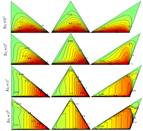
Figure 2 represents the streamlines for several thermal Rayleigh numbers in three cases of the experiments. It is found that different geometry shapes and different thermal Rayleigh numbers significantly affect the streamlines. A fine distinction among the streamlines can also be observed through all the cases. For Rayleigh number, R a_{T}=10^{5}, one loop of streamlines rotates in the entire cavity throughout the cases. There exist momentum boundary layers on the boundaries. The cores of the streamlines are found exactly at the centroid of the cavities. The spreading streamlines in the cavities tend to be elongated to the corners of the cavities. There are also some subtle differences in the streamlines in the three cavities in this case. The core of the streamlines of the right and acute-angled triangular cavities are not that much influenced by the corners whereas this is significantly distracted by the vertices in the obtuse-angled cavity. For R a_{T}=10^{6}, the streamlines are started to form like the corresponding cavities. The cores of the streamlines are shifted to the upsides from the original position. The densities and strengths of streamlines are slightly increased than that of R a_{T}=10^{5}. The streamlines in the obtuse-angled cavity are comparatively very active than that of the other two cases. A strong vortex of streamlines is formed on the left sloping wall of the obtuse-angled cavity indicates early convection happens by this specific formation. Also, it is important to note that the strength of the streamlines in the right-angled cavity is slightly more than that of the acute-angled cavity.
Figure 2. Streamlines for different R a_{T} in (a) case-1\left(1^{\text {th }} \text { column) (b) case- } 2\left(2^{\text {nd }} \text { column) and (c) case-3 ( } 3^{\text {rd }} \text { column) for } \phi=\right.\right. 0.05, d_{p}=10 \mathrm{nm}, \mathrm{Ha}=20, \gamma=90^{\circ} \mathrm{at} \tau=0.1 (steady state)
For thermal Rayleigh number, R a_{T}=10^{7}, the streamlines are significantly distorted and the densities of streamlines are increased throughout and then that of the previous the cases. The deformations of streamlines happen in the middle of the cavities. The streamlines upwardly elongate in this case. Comparatively, full-bodied streamlines happen in the first two cases whereas little more distortions of streamlines can be seen in the acute and obtuse-angled cavities than that of the right-angled cavity. However, three strong vortices formed on the right sloping wall only in the obtuse-angled cavity in this case. A thoughtful flow of nanofluids can be seen for R a_{T}=10^{8}. It is found that that the streamlines are distorted in the entire cavities. The convective cells spread in every part of the cavities. A flow drain is found near the boundaries of the cavities shows an amazing convective flow in this case. Small but very active clockwise and anticlockwise vortices are seen all over the cases. However, comparatively, slightly more convective cells are found in the acutely angled cavity than that of the other two cases. So, it can be concluded that the flow strength increases remarkably as the thermal Rayleigh number increases. Little differences in the flow strengths have been encountered in the three different triangular cavities; but for small temperature differences, early convective cells can be seen in the obtuse-angled triangular cavity. For a higher Rayleigh number; slightly more convective cells are found for the acute-angled triangle.
The effects of the various values of thermal Rayleigh number in terms of isothermal lines in three distinct shapes of triangular cavities for a particular situation have been depicted in Figure 3.
Figure 3. Isotherms for different R a_{T} in (a) case- 1\left(1_{w}^{\text {st }} \text { column }\right) (b) case- 2\left(2^{\text {nd }} \text { column) and (c) case- } 3 \text { ( } 3^{\text {rd }} \text { column) for } \phi=0.05\right. d_{p}=10 n m, H a=20, \gamma=90^{\circ} at \tau=0.1 (steady state)
The thermal Rayleigh number and the shapes of the triangular cavity significantly affect the pattern and strength of the thermal flow. Isotherm line represents the heat line and shows how the heat passes through the nanofluid to the colder walls from the lower heated wall. For the lower thermal Rayleigh number, R a_{T}=10^{5} the isotherms do not spread to the entire cavities, they compress to the heated wall. This is due to the lower temperature differences where nanofluid receipts heat from the heated wall and uninspired nanoparticles carry this heat to the leaning colder walls. The isothermal cells are parallel to each other and the distortions of heat lines are not that much represent that the conduction governs in the cavities. The conductive cells are spreading faintly towards the topmost vertex. The levels of the cells are closed to zero indicate that the thermal strengths are very poor. For the increment of thermal Rayleigh number up to R a_{T}=10^{6}, we have seen that the isotherms are slightly extended as curves and twisted little bit in the middle of the cavity showed pure convection. The isotherms have intended to extend to the upper vertex adjacent to the right side wall from the right corner of the triangle in all circumstances. Nevertheless, for an obtuse-angled triangle, the isotherms extend upwards from the right corner of the triangle, which indicates that the convection mode of heat transfer in the enclosure starts early than that of other cases. For the higher thermal Rayleigh number R a_{T}=10^{7}-10^{8}, the deformations of heat lines are significant, cells are distributed vertically adjacent to the colder walls and remarkable distortions can be observed near the cooler boundaries. It is also found that the convective cells are thermally very energetic in the enclosures. The full-bodied thermal cells take energy from the lower heated wall smoothly and pass it through the other two walls due to the higher thermal flow for the higher temperature differences. These designate that the convection happens in the entire cavities. However, note that unorthodox dissemination of isotherms is found close to uppermost vertex of the obtuse-angled triangular enclosed associated to that of the further two circumstances.
4.2 Effects of nanoparticle volume fraction in three cavities on streamlines and isotherms
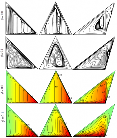
The flow field in terms of streamlines and the thermal field in terms of isotherms for nanofluid (\phi=0.1) and base fluid (\phi=0.0) within three different triangular-shaped cavities are presented in Figure 4. The streamlines, as well as isotherms for base fluid and nanofluid, are remarkably dissimilar. The geometrical shapes, as well as nanoparticles, strike the pattern of the flow and thermal fields. Streamlines for base fluid are vigorous but roughly associated with one another. The distribution of streamlines is not uniform in the cavities. They concur in the different parts of the cavities. Bunch of cells of streamlines rotates actively in the middle of the cavities. Momentum boundary layers on the boundaries of the triangles are absent for base fluid. Noticeably, convective cells of the streamlines vertically lengthen in the right and acute-angled triangles whereas the cells horizontally elongate in the obtuse-angled triangle and three small vortices are also visible in this case. Conversely, for nanofluid, the densities and uniformities of the cells of the streamlines enhance considerably than that of conventional fluid because of the presence of solid particles. Nanoparticles produce extra force, friction, and viscosity in the base fluid as well. Various high-pitched cores of the vortices form in the cavities due to the random motions and migrations tendency of concentrated nanoparticles. Streamlines distort to some extent in the middle of the cavities because of the thermal convection of the solid-liquid mixture. Amazing full-bodied streamline distribution can be observed in this case. Momentum boundary layers are pronounced on the walls of the triangular cavities. The streamlines elongate vertically towards the colder walls. Convective cells of the streamlines tend to reach to the colder walls. These are due to the advanced thermal conductance and phonon characteristics of solid who can take significant heat from the heated boundary. Note: streamlines of nanofluid filled obtuse-angled triangular cavity are smoother than that of the other cases. Also, a strong vortex exists on the right sloping wall; indicates higher convective performances. The density of the convective cells of streamlines near the boundaries of the right-angled triangle is higher than that of the acute-angled triangle. Figure 4 further illustrates the changes of isotherms due to the triangular shapes for base fluid as well as nanofluid. We found that the shapes of the triangular cavity and nanoparticle volume fraction significantly affect the pattern of isotherms. The vigorous and strongly connected isotherms have been seen for base fluid whereas isotherms for nanofluid are slightly compacted to heated boundaries and not that much invigorated because the stickiness and molecular density of conventional fluid are less than that of nanofluid. The base fluid molecules can contain heat from the source boundary and straightaway transfer to the cooler partitions. The molecular activity for base fluid inside the cavities is insignificant in this case which creates slow migration of heat.
Almost analogous convection has been observed throughout the cavities for base fluid whereas, for nanofluid, the intensity of the convective cells of isotherms is progressive within the obtuse-angled triangular cavity than that of the other two cases. Importantly, isotherms for nanofluid filled cavities are different because nanoparticle works as carrier in heat transfer. Nanoparticles migration and collisions within a geometrical constraint is a crucial mechanism in heat transportation. For nanofluid, isotherms slightly compress towards the lower heated wall. Deformations of convective cells near the boundary walls are significantly higher than that of the other spaces of the cavities which indicate that maximum convection happens adjacent to the boundaries.
Figure 4. Streamlines \left(1^{\text {th }} \text { two rows) and Isotherms (2 }^{\text {nd }} \text { last two rows) for different } \phi \text { and for (a) case- } 1\left(1^{\text {st }} \text { column ) (b) case- } 2\right.\right. \left(2^{\mathrm{nd}} \text { column }\right) and (\mathrm{c}) case- 3\left(3^{\mathrm{rd}} \text { column }\right) for R a_{T}=10^{6}, d_{p}=10 n m, H a=25, \gamma=90^{\circ} \mathrm{at} \tau=0.1(\text { steady state })
4.3 Effects of the Rayleigh number on the local Nusselt number on a cut-line of the cavities
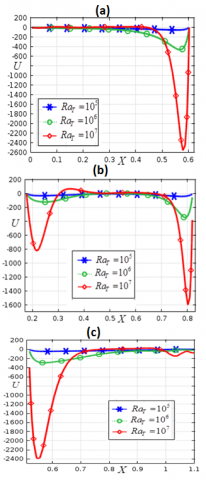
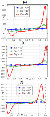
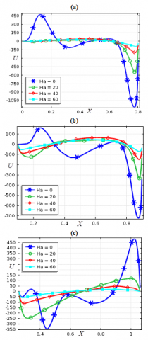
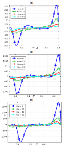
The velocity U distributions for different thermal Rayleigh number on a line inside the geometry at Y=0.2 have been depicted in Figure 5 for (a) right-angled triangular, (b) acute-angled triangular and (c) obtuse-angled triangular cavity. The distributions of velocity U are negative throughout the cases. For the lower value of R a_{T}, the velocity U profile is almost a straight line and it coincides at U=0. If R a_{T} has been increased, the velocity U distribution has been increased to the negative Y-axis significantly indicates that clockwise rotations of the nanofluid flow increase in the cavity. The multiple maximum negative U-velocity values for the higher Rayleigh number have been obtained at different positions of the cut-line throughout the cases. The maximum negative velocity U has been observed at the right side of the right-, and acute-angled triangular cavity presented in Figures 5(a) and 5(b), correspondingly, whereas for the obtuse-angled triangular cavity it has been found at the left side as shown in Figure 5(c). Two downward curves on the two verges of the line represented the velocity U distribution for acute-angled triangular cavity whereas only one downward curve characterized velocity U profile for additional two cases. This indicates that the profile of flow velocity U is highly influenced by the thermal Rayleigh number for acute-angled triangular cavity than that of the other two cases. The V-velocity profiles for several thermal Rayleigh numbers in three different triangular cavities are represented in Figures 6(a)-(c). For the various values of thermal Rayleigh number and three shapes of triangular cavities, the V-velocity profile slightly changes. The V-velocity distribution along the cut line becomes a straight line when V = 0 for the lower values of R a_{T}. As R a_{T} enhances; the V-velocity profiles expanse significantly within negative and positive values of V throughout the cases. This indicates that there exist clockwise and counterclockwise rotations of the nanofluid flow for the V-velocity. The maximum and minimum V-velocities are found on the two sides of the cut-line of all three cavities and they are comparatively higher for the acute-, and obtuse-angled cavities. In the middle of the cut line, the velocity profiles are almost a straight line with nearly zero velocity. The V-velocity profiles for different thermal Rayleigh number are not that much expansive but more distinguishable for the right-angled triangular cavity than that of other two cases whereas notably, a sharp V-velocity distribution is seen in case of the obtuse-angled triangular cavity.
Figure 5. Velocity in x-component (a) right (b) acute and (c) obtuse angled triangle for \phi=0.05, d_{p}=10 \mathrm{nm}, \mathrm{Ha}=25, \gamma=90^{\circ} at \tau=0.1
Figure 6. Velocity in y-component (a) right (b) acute and (c) obtuse -angled triangle for \phi=0.05, d_{p}=10 \mathrm{nm}, \mathrm{Ha}=25, \gamma=90^{\circ} at \tau=0.1
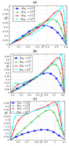
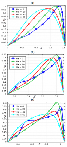
Figure 7. Effects of temperature for (a) right (b) acute and (c) obtuse -angled triangle for \phi=0.05, d_{p}=10 \mathrm{nm}, \mathrm{Ha}=25, \gamma=90^{\circ} at \tau=0.1
Figure 8. Effects of local Nusselt number for (a) right (b) acute and (c) obtuse -angled triangle for \phi=0.05, d_{p}=10 \mathrm{nm}, \mathrm{Ha}=25, \gamma=90^{\circ} at \tau=0.1
The temperature distribution for various values of R a_{T} on a horizontal line at Y=0.2 within the three triangular-shaped cavities are demonstrated in Figures 7 (a)-(c). The temperature profile has been significantly affected by the changes of buoyancy parameter and shapes of the triangular cavities. The temperature profile fluctuates on approximately X \in[0.1,0.52] and then enhances significantly on the horizontal line in right-angled triangular enclosure as the buoyancy-driven parameter rises. However, for the acute-, and obtuse-angled triangular cavities, the temperature profile increases significantly for R a_{T}=10^{5}-10^{7} and for R a_{T}=10^{8}, temperature profile fluctuates somewhat in the middle of the cut-line. Interestingly, the temperature distribution improves greatly in all cases at left and right positions of horizontal line as the thermal Rayleigh number enriches. The noticeable expansion of temperature profiles for different Rayleigh number has been seen for the obtuse-angled triangular cavity shown in Figure 7(c) than that of the other cases. The concentrated temperature ensues at the right part of the cut-line throughout the cases. The optimum temperature is noticed at R a_{T}=10^{7} for obtuse-angled triangular cavity whereas this is higher for the acute-angled triangular cavity at R a_{T}=10^{8}.
Figure 8 illustrates the heat transfer distribution at the lower base wall of the three diverse triangular cavities for the different Rayleigh number for a specific case. We have observed that the heat transfer distribution upsurges significantly as the Rayleigh number rises and the patterns of the local Nusselt number dispersal are virtually equivalent in all conditions. The utmost heat transfer for several Rayleigh numbers is noticed at two sides of the bottom wall while extremely lower heat transfer has been detected at the middle of the heated wall for the lower thermal Rayleigh number throughout the cavities. The heat transfer curve is touched at peak point at the left side of the base wall then plummeted rapidly for a certain point. After that, it is gradually decreased in the middle of the wall to a certain number on the right side and then swiftly increased. Comparatively a little higher heat transfer distribution has been found lower base boundary of the obtuse-angled triangular cavity than that of other triangular cavities.
4.4 Effect of time evolution in terms of the local Nusselt number for three cavities
The heat transfer at the various point on the horizontal cut-line at Y=0.4 of three distinct triangular cavities for applied temperature and different time steps are exhibited in Figures. 9 (a)-(c). It is found that the patterns of local Nusselt number distribution on the cut-line of right-, and acute-angled triangular cavities are nearly similar (Figure 9(a) and 9(b)), while entirely dissimilar for the obtuse-angled triangular cavity (Figure 9(c)). The distribution of local Nusselt number concerning temperatures for different time steps looks like a nice lefty open loop for the right-, and acute-angled triangular cavities whereas, for the obtuse-angled triangular cavity, they are self-intersecting three-sided loops. As the time step increases, the distributions of the local Nusselt number upturn pointedly for a fixed range of time steps, after that, coincides to each other at a certain period means that the steady-state solution occurs for this specific arrangement. The steady-state solutions in these circumstances are arisen at \tau=0.011, \tau=0.012 and \tau=0.014 for right-, acute-, and obtuse-angled triangular cavities, respectively. Note: the maximum heat transfer has been observed for the acute-angled triangular cavity at temperature, \theta=0.26 at the middle of the right side of cut-line.
The time evolutions are further checked for the heat transfer disseminations for U-velocity of nanofluid on a horizontal line at Y=0.4 within three cavities in Figures 10 (a)-(c). The heat transfer distributions for three cavities are considerably dissimilar. As the time steps develop, the heat transfer on the cut-line enhances significantly throughout the cases for a certain period of the time step. The steady-state solutions are occurred in this case at \tau=0.011, \tau=0.011 and \tau=0.013 for right-, acute-, and obtuse-angled triangular cavities, respectively. The left side of the cut-line within the cavities bears comparatively higher negative U-velocity to higher heat transfer distribution. The heat transfer distributions for several time steps occurred for only the negative U-velocity inside right-angled triangular enclosure (Figure 10 (a)), whereas they are disseminated for the negative and also to some extent positive U-velocity in the other two instances exposed in Figures 10 (b)-(c). The maximum value of the local Nusselt number is found when U = - 40, U = -25 and U = 0 for the right-, acute-, and obtuse-angled triangular cavities, respectively.
Figures 11 (a)-(c) distinguish the time evolution of the experiment in terms of heat transfer distribution versus the obtained flow velocity-V on a line at Y=0.4 within the (a) right-, (b) acute-, and (c) obtuse-angled triangular cavity. As can be seen that the triangular shapes and time remarkably affect the heat transfer distributions. The heat transfer at several points of the line for the V-velocity are dissimilar in all cases and to some extent, they look like a fishhook device.
Figure 9. Time evolution in terms of Nusselt number versus temperature for (a) right (b) acute and (c) obtuse-angled triangle for \phi=0.05, d_{p}=10 \mathrm{nm}, \mathrm{Ha}=25, \gamma=90^{\circ} \mathrm{at} \tau=0.1
The local Nusselt number distributions are displayed by the negative and positive V-velocities indicate that the V-velocity significantly contributes to the clockwise and counterclockwise rotations of the streamlines in the fluid flow. The negative V-velocity works on the left-hand side of the cut-line while the positive flow velocity-V functions at the right side. Interestingly, the extremum value of the local Nusselt number has been obtained at the right side of the cut-line for the positive flow velocity-V and its minimum value is encountered for negative V-velocity. The maximal local Nusselt number for the flow velocity-V has been perceived for the acute-angled triangular cavity than that of other cases. The heat transfer significantly changes over the periods. As the time rises up to a certain value, the heat transfer disseminations on the line within cavities enhances expressively. The enhancement in heat transfer spreading is significant on this occasion. The steady-state solution directly depends on the parametric diversity as well as the space and time of the problem. Steady-state solution of the heat transfer parameter for the flow velocity-V occurs at \tau=0.013, \tau=0.012 and \tau=0.019 for right-, acute-, and obtuse-angled triangular cavities, respectively.
Figure 10. Time evolution in terms of Nusselt number versus U-velocity for (a) right (b) acute and (c) obtuse-angled triangle for \phi=0.05, d_{p}=10 \mathrm{nm}, \mathrm{Ha}=25, \gamma=90^{\circ} \mathrm{at} \tau=0.1
Figure 11. Time evolution in terms of local Nusselt number versus V-velocity for (a) right (b) acute and (c) obtuse -angled triangle for \phi=0.05, d_{p}=10 \mathrm{nm}, \mathrm{Ha}=25, \gamma=90^{\circ} \mathrm{at} \tau=0.1
4.5 Variations of the average Nusselt number in different cavities
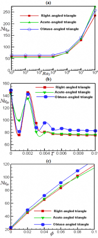
The variations of N u_{a v} over the heated wall of the three distinct triangular shaped cavities for several values of R a_{T}, \tau, \phi are illustrated in Figures 12(a)-(c). The Nusselt number, N u_{a v} for three cavities versus the various values of R a_{T} is presented in Figure 12(a). It is observed that the mean Nusselt number is plateaued for R a_{T} \leq 10^{5} throughout the cavities indicate the conduction in the enclosures. Noticeably, rapid enhancement in heat transfer has been observed in all cases for R a_{T}> 10^{5}. This is a signpost that the critical value of the buoyancy parameter for the current physical system is R a_{T} =O(10^{5}). It is imperative to note that the operations of three triangular cavities in the energy transfer improvement openly depend on the thermal Rayleigh number. Additionally, the higher heat transfer occurs in the obtuse-angled triangular cavity for R a_{T} \leq 10^{7} than that of the other two cavities but for R a_{T} >10^{7}, the acute-angled triangular cavity exhibits pointedly higher heat transfer rate in the analysis.
Figure 12. Mean heat transfer against (a) buyancy parameter, (b) time, and (c) solid volume fraction for d_{p}=10 \mathrm{nm}, \phi=0.05, \mathrm{Ha}=25, \gamma=90^{\circ} at \tau=0.1.
Alternatively, the minimum average heat transfer in the investigation has been exhibited using the acute-angled triangular cavity for R a_{T} \leq 10^{6}. Nevertheless, at R a_{T} > 10^{6}, the minimum heat transfer is noticed for the right-angled triangular cavity. The average heat transfer for various time steps in the three unlike triangular cavities when d_{p}=10 \mathrm{nm}, \phi=0.05, \mathrm{Ha}=25, \gamma=90^{\circ} has been shown in Figure 12(b). As can be seen that the average heat transfer fluctuates in the initial time steps and after a certain period, it becomes steady for all cases. The average Nusselt number is more pronounced and higher for the obtuse-angled triangular cavity than that of other two cavities studied in the analysis. However, early steady-state solution in terms of average Nusselt number occurs for the acute- and right-angled triangular cavities than that of the obtuse-angled triangular cavity. After the initial fluctuation, the heat transfer rate for the acute-, and right-angled trilateral vessels are almost similarly over the periods. Finally, the mean heat transfer at the heated wall of the three different trilateral cavities versus the solid volume fraction is illustrated in Figure 12 (c). The average heat transfer upsurges outstandingly as the nanoparticle volume fraction upsurges. Additionally, the performances of the three cavities are depicted in this figure. Comparatively, the obtuse-angled trilateral cavity shows higher average heat transfer on the heated wall than that of other cavities considered in the analysis. Interestingly, the augmentation in heat transfer for several nanoparticle volume fractions up to \phi \in\lceil 0,0.065\rceil over the heated boundary of the acute-angled deltoid vessel is higher than that of the right-angled triangular cavity. Conversely, for \phi>0.065, the augmentation in heat transfer is higher for the right-angled three-cornered enclosure than that of the acute-angled trilateral cavity.
4.6 Effects of magnetic field parameter and magnetic field inclination angle
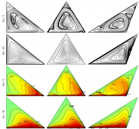
The effects of magnetic field parameter (Ha) in terms of isotherms and streamlines in three different shapes of triangular cavities have been demonstrated in Figure 13. For Ha=0, active and strong rotational streamlines along with some small but resilient vortices have been observed throughout the case. Significant distortions of streamline are seen in the entire cavities because the fluid flows are independent of the external force but dependent over the internal and external temperature. Importantly, small strong vortices are visible at colder walls as well as a large whirlpool is comprehended in the middle of the enclosure elongates to three corners of the enclosure. Also, active small vortices formed to the uppermost vertex of the enclosure in the core of a big vortex. These indicate that the streamlines are significantly affected by the cavity shapes. Comparatively, substantial distortion of streamlines has been seen within the obtuse-angled triangular cavity than that of the other two cases. This happens because the upper slanting colder wall of the obtuse-angled vessel is nearer to the heated wall. Contrarily, streamlines are uniform in a large vortex blowout within the whole cavity for the presence of the Hartmann number in all cases where a core of contours has been found in the middle. This is due to the magnetic field lines reconnect particles motion as soon as solid nanoparticle clashes and control particles diffusivities lead to breaking in magnetic topology. Among the three cavities, streamlines densities and strengths inside the obtuse-angled triangular vessel are relatively higher than that of the other vessels. Additionally, a small vortex on the vertically leaned wall of the obtuse-angled cavity is visible indicates that higher magnetic fields intensity requires at this particular portion to control fluid swirling. This figure further illustrates the effects of Hartmann number over isotherms in three triangular cavities. Without the magnetic field parameter, asymmetric, robust and distorted isotherms have been observed throughout the cases. A dilute soaring thermic coating is found on the heated surface of the cavities.
The levels of contours are almost analogous in the entire cavities indicates that higher heat transfer encounters. The random collisions and migrations of particles produce thermal motion that is not affected by any external forces in this case. Importantly, the pattern and distribution of isotherms are dissimilar within the three cavities. This ensures that the shape of the cavity contributes to heat transfer development. The obtuse-angled triangular cavity shows higher convection cells and thermal convolutions than that of the other two cases. Conversely, isotherms lines are compressed towards the heated wall for the presence of the magnetic intensity indicate that for conduction governs in the heat transfer application. The isotherms are not that much distorted and twisted in the middle as well as at the slanting walls of the cavities. The leveling of the isotherms are poor in the middle of the cavities and advanced thermic wall coating thickness has been detected at the animated base wall which directs that magnetic field control and lowers the heat transfer in application. The levels of contours are almost analogous in the entire cavities indicates that higher heat transfer encounters. The random collisions and migrations of particles produce thermal motion that is not affected by any external forces in this case. Importantly, the pattern and distribution of isotherms are dissimilar within the three cavities. This ensures that the shape of the cavity contributes to heat transfer development. The obtuse-angled triangular cavity shows higher convection cells and thermal convolutions than that of the other two cases. Conversely, isotherms lines are compressed towards the heated wall for the presence of the magnetic intensity indicate that for conduction governs in the heat transfer application. The isotherms are not that much distorted and twisted in the middle as well as at the slanting walls of the cavities. The leveling of the isotherms are poor in the middle of the cavities and advanced thermic wall coating thickness has been detected at the animated base wall which directs that magnetic field control and lowers the heat transfer in application.
Figure 13. Streamlines (1st two rows) and isotherms (last two rows) for different Ha and for (a) case-1 (1st column) (b) case-2 (2nd column) and (c) case-3 (3rd column) for R a_{T}=10^{6}, d_{p}=10 n m, \phi=0.05, \gamma=90^{\circ} at \tau=0.1
Figures 14 (a)-(c) represent the U-velocity profiles at the horizontal cut-line Y=0.2 of right-, acute- and obtuse-angled triangular cavities on behalf of standard values of Hartmann number respectively. The U-velocity profiles are dissimilar for three different triangular cavities. Negative and positive flow velocity-U are on horizontal line characterizes clockwise and counterclockwise rotations of the vortices. The maximum value of U for both anticlockwise and clockwise rotating vortex have been found for the right-angled trilateral enclosure exposed in Figure 14(a) while the minimum U-velocity for anticlockwise rotational vortex has been observed for the acute triangle displayed in Figure 14(b).
However, minimum U-velocity for clockwise vortices is noticed for the obtuse-angled triangular cavity shown in Figure 14 (c). Interestingly, the maximum positive U-velocity for both right- and obtuse-angled-triangular cavity at two opposite sides of the cut line are similar. We have also seen that U-velocity decreases significantly within the cavities as the magnetic field parameter enhances. For the higher intensity of magnetic field parameter the U-velocity profile is almost a straight line throughout the cases whereas it looks like an unsteady growth with fluctuations upward and downward for lower values of Hartmann number. When Ha=0, U-velocity distribution is almost analogous for both right- and acute-angled triangular cavities while its reverse distribution has been found for an obtuse-angled triangular cavity.
Figure 14. Effects of Hartmann number on U-velocity for (a) right- (b) acute- and (c) obtuse-angled triangle for \phi=0.05, d_{p}=10 \mathrm{nm}, R a_{T}=10^{6}, \gamma=90^{\circ} at \tau=0.1
Figure 15 (a)-(c) illustrates the V-velocity profile for diverse measures of Hartmann number at the horizontal cut-line Y=0.2 within right-, acute, and obtuse-angled triangular cavity respectively. The positive and negative values of V-velocity are lessened as the magnetic field parameter is raised which suggests that the fluid motion decreases significantly for the increment in magnetic field intensity. For radical measures of Hartmann number, the flow velocity-V distribution along the cut line becomes practically a straight line coincides at V=0 whereas for Ha=0, the V-velocity profile expanses significantly within negative and positive values of V throughout the cases. The maximum positive and negative V-velocities are found for Ha=0 on the two sides of the cut-line of all three cavities and they are relatively higher for the acute-angled triangular vessel revealed in Figure 15 (b).
The temperature visibilities at the horizontal cut-line Y=0.2 of the three triangular shape cavities for different Hartmann number are shown in Figure 16(a)-(c). The temperature profile fluctuates for numerous measures of Hartmann number. The maximal temperature occurs on the right part of the cut-line in all cases. The temperature profiles enhance as the Hartmann number enhances for nearly X \in[0,0.6] on the cut-line of the right-angled triangular cavity and X \in[0.1 ,0.8] on the cut-line of other two cases while profiles are shrunk on the rest of the cut-line. The maximum temperature occurs when Ha=0 within a right-angled three-sided enclosure; in contrast, it arises when Ha=20 for the other two cavities.
Figure 15. Effects of Hartmann number on V-velocity for (a) right (b) acute and (c) obtuse-angled triangle for \phi=0.05, d_{p}=10 \mathrm{nm}, R a_{T}=10^{6}, \gamma=90^{\circ} at \tau=0.1
The effects of the Hartmann number concerning the heat transfer distribution over the horizontal cut-line at Y=0.2 is portrayed in Figure 17 (a)-(c) respectively within right-, acute- and obtuse-angled triangular cavities. The heat transfer distribution is inconsequential for the presence of the magnetic field parameter whereas noticeable heat transportation ensues for the absence of electric conductance. As the Hartmann number upturns, heat transfer declines considerably. Notably, for the higher magnetic intensity, the heat transfer tends to zero at the cut-line throughout the cases. Comparatively higher heat transfer occurred on the cut-line of the obtuse trilateral enclosure than that of the other cases.
The impacts of magnetic field parameter (Ha) and magnetic field inclination angle (\gamma) on the mean Nusselt number at the lower heated wall have been displayed in Table 5. The typical heat transfer rate is lessened as the magnetic flux is augmented throughout the cases. The average heat transfer in the nonexistence of magnetic flux parameter is significantly higher than that of the existence of a magnetic field. Among three different cavities, obtuse-angled triangular enclosure exhibits higher average heat transfer than that of other two cavities for several measures of the Hartmann number. The right- and acute-angled triangular cavities show almost similar average heat transfer through the heated wall for numerous Hartmann number. The effects of the magnetic field inclination angle (\gamma=0^{\circ}-90^{\circ}) also depicted in Table 5. The average heat transfer rate for \gamma=0^{\circ}-90^{\circ} remains more eminent for the obtuse-angled triangular cavity compared to the other cases; in which almost similar average heat transfer rate is found. Average heat transfer on the animated base wall decreases pointedly for \gamma \left(0^{\circ}-90^{\circ}\right) for both right- and acute-angled triangular cavity whereas it fluctuates for the obtuse-angled triangular enclosure. The maximum average heat transfer has been found at \gamma=0^{\circ} for both right- and acute-angled triangular cavity and at \gamma=20^{\circ} for obtuse-angled triangular enclosure.
Table 5. Effects of magnetic field parameter (Ha) and magnetic field inclination angle (\gamma) at the heated wall of right-, acute- and obtuse-angled triangular cavities \phi=0.05, d_{p}=10 \mathrm{nm}, R a_{T}=10^{6}, at \tau=0.1
|
Case-1 |
Case-2 |
Case-3 |
||||||
|
Ha |
\gamma |
N u_{a v} |
Ha |
\gamma |
N u_{a v} |
Ha |
\gamma |
N u_{a v} |
|
0 |
900 |
102.98 |
0 |
900 |
102.99 |
0 |
900 |
109.43 |
|
20 |
900 |
80.35 |
20 |
900 |
81.92 |
20 |
900 |
88.28 |
|
40 |
900 |
65.08 |
40 |
900 |
64.12 |
40 |
900 |
71.53 |
|
60 |
900 |
60.67 |
60 |
900 |
58.27 |
60 |
900 |
66.60 |
|
25 |
00 |
85.79 |
25 |
00 |
81.30 |
25 |
00 |
95.01 |
|
25 |
200 |
80.76 |
25 |
200 |
79.51 |
25 |
200 |
100.61 |
|
25 |
400 |
76.19 |
25 |
400 |
77.73 |
25 |
400 |
98.36 |
|
25 |
600 |
73.93 |
25 |
600 |
76.79 |
25 |
600 |
90.21 |
|
25 |
900 |
74.76 |
25 |
900 |
75.73 |
25 |
900 |
82.02 |
Figure 16. Effects of Hartmann number on temperature for (a) right (b) acute and (c) obtuse -angled triangle for \phi=0.05, d_{p}=10 n m, R a_{T}=10^{6}, \gamma=90^{\circ} at \tau=0.1
Figuer 17. Effects of Hartmann number on local Nusselt number for (a) right (b) acute and (c) obtuse -angled triangle for \phi=0.05, d_{p}=10 \mathrm{nm}, R a_{T}=10^{6}, \gamma=90^{\circ} at \tau=0.1
4.7 Flow resistance characteristics of nanofluid
The flow resistance characteristics of nanofluids are calculated by f=2 \mu_{n f}\left(\frac{\partial U}{\partial x}+\frac{\partial U}{\partial Y}\right) / \rho_{n f} \bar{U}^{2} (see, [54]) at the horizontal cutline in the triangular cavities. This formula is known as Fanning friction factor. Figure 18 describes the effects of friction factor within the cutline at Y=0.4 of (a) right- (b) acute- and (c) obtused-angled triangular cavities for three distict values of the nanoparticle volume fraction. The effects of the friction with the surface, walls and inside the cavities are noticed in nanoscales. The dissimilar affects of the friction factors are detected for different cavities. Frictions in the cavities for the base fluid is significantly higher than that of the nanofluid. As the nanoparticle volume fraction is increased, the frictions almost diminished in the nanofluid flows in all cases. For the right-angled triangular cavity, the frictions are negative at the middle of the cavity and rest of the cutline shows a frictionless flow. This indicates that friction in the middle of right-angled triangular cavity speeds up the flow in opposite direction. For the isosceles triangular cavity, at X=0.2 to X=0.28, equal amont of positive and negative values of the friction factor occurs and on the rest of the cutline, it shows almost a smooth nanofluid flow. This indicates that higher force is necessitated to accelerate the nanofluid flow at X=0.2-0.28 in this case. For obtuse-angled triangular cavity, positive friction occurs only near at the left sloping wall and the negative friction observes at X=0.4 and near at the right slanting wall on the cutline. So, it is concluded that nanofluid filled vessel shows very insignificant effects of the frictions compared to the base fluid and frictions in obtuse-angled triangular cavity are less than that of the other cavities.
Figure 18. Effects of the Fanning friction factor on the cutline at Y=0.4 for (a) right-, (b) acute- and (c) obtuse angled triangle for three distinct values of \phi when d_{p}=10 n m, R a_{T}=10^{6}, \gamma=90^{\circ} at \tau=0.1
The water-cooper oxide nanofluid flow and convection inside the three different shapes of triangular cavities are studied numerically. The horizontal barrier of the enclosures is homogeneously heated while other walls are assumed to be comparatively colder. In the experiment, the effects of the shapes of the triangular cavities along with the different pertinent parameters of the problem are investigated. The heat transfer distributions with respect horizontal lines within the cavities for related parameters are analyzed and equated. To discovery the steady-state result, the time evolution about mean heat transfer has been computed. The results demonstrate that the flow patterns and the heat transfer distribution in the three different types of triangular cavities are dissimilar for certain circumstances. For the lower thermal Rayleigh number, early convection happens in the obtuse-angled triangular cavity whereas, for a higher thermal Rayleigh number, slightly more convection mode of heat transfer dominates in the acute-angled triangular cavity than that of the other cases. The critical thermal Rayleigh number for the onset of convection for the present problem is found to be O(105). For higher thermal Rayleigh number, the acute-angled triangular cavity exhibits higher heat transfer rate whereas the right-angled triangular cavity shows lower heat transfer rate than that of the other cases. The higher enhancement in heat transfer for several nanoparticle volume fractions occurs within the obtuse-angled triangular cavity than that of the other cases analyzed in the experiment. The presence of a magnetic field reduces the heat transfer rate in nanofluid applications. The frictions within the cavities are higher for base fluid than that of the nanofluid. Obtuse- angled triangular cavity shows lower effect of the friction factor.
|
AR |
height/base length of the cavities [m] |
|
b |
magnetic field vector |
|
b0 |
magnitude of the magnetic field [N·m−1·A−1] |
|
cp |
specific heat [J.kg-1.K-1] |
|
dp |
particle diameter [nm] |
|
DB |
diffusion coefficient (Brownian) [m2.s-1] |
|
DT |
diffusion coefficient (thermophoresis) [m2.s-1] |
|
D_{T}^{\ell} |
constant, dimensionless |
|
g |
gravity vector |
|
g |
gravity [m.s-2] |
|
H |
cavity height [m] |
|
kB |
Boltzmann constant, [J.K-1] |
|
Ha |
Hartmann number, dimensionless |
|
L |
cavity length [m] |
|
Nu |
Nusselt number, dimensionless |
|
n |
empirical shape factor, dimensionless |
|
P |
pressure, dimensionless |
|
p |
pressure [Pa] |
|
Pr |
Prandtl number, dimensionless |
|
qw |
heat flux [W.m-2] |
|
RaT |
Rayleigh number, dimensionless |
|
T |
temperature [K] |
|
Tc |
lower reference temperature [K] |
|
Th |
higher reference temperature [K] |
|
u,v |
flow velocities [m.s-1] |
|
U,V |
velocity components, dimensionless |
|
x,y |
co-ordinates [m] |
|
X,Y |
nondimensional coordinates |
|
Greek symbols |
|
|
\alpha |
diffusivity (thermal) [m2s-1] |
|
\beta |
thermal expansion coefficient [K-1] |
|
\gamma |
sloping tilt of magnetic field [deg] |
|
\theta |
temperature, dimensionless |
|
\phi |
nanoparticle volume fraction, dimensionless |
|
\kappa |
conductivity (thermal) [W.m-1.K-1] |
|
\mu |
dynamic viscosity [kg.m-1.s-1] |
|
\psi |
stream function, [m2.s-1] |
|
\Psi |
sphericity, dimensionless |
|
\rho |
density [kg.m-3] |
|
\rho c_p |
heat capacity [J.K-1.m-3] |
|
\upsilon |
kinematic viscosity [m2.s-1] |
|
ƛ |
correction factor, dimensionless |
|
\sigma |
electrical conductivity [ S.m-1 ] |
|
\omega |
vorticity, [s-1] |
|
Subscripts |
|
|
nf |
nanofluid |
|
av |
mean |
|
p |
solid nanoparticle |
|
bf |
base fluid |
[1] Kaushik, S.C., Kumar, R., Garg, H.P., Prakash, J. (1994). Transient analysis of a triangular built-in-storage solar water heater under winter conditions. Heat Recovery Systems and CHP, 14(4): 337-341. https://doi.org/10.1016/0890-4332(94)90037-X
[2] Asan, H., Namli, L. (2000). Laminar natural convection in a pitched roof of triangular cross-section: Summer day boundary conditions. Energy and Buildings, 33(1): 69-73. https://doi.org/10.1016/S0378-7788(00)00066-9
[3] Omri, A., Orfi, J., Nasrallah, S.B. (2005). Natural convection effects in solar stills. Desalination, 183(1-3): 173-178. https://doi.org/10.1016/j.desal.2005.04.025
[4] Anandalakshmi, R., Basak, T. (2012). Heat flow visualization for natural convection in rhombic enclosures due to isothermal and non-isothermal heating at the bottom wall. International Journal of Heat and Mass Transfer, 55(4): 1325-1342. http://dx.doi.org/10.1016/j.ijheatmasstransfer.2011.09.006
[5] Flack, R.D., Konopnicki, T.T., Rooke, J.H. (1979). The measurement of natural convective heat transfer in triangular enclosures. Journal of Heat Transfer, 101(4): 648-654. https://doi.org/10.1115/1.3451051
[6] Flack, R.D. (1980). The experimental measurement of natural convection heat transfer in triangular enclosures heated or cooled from below. Journal of Heat Transfer, 102(4): 770-772. https://doi.org/10.1115/1.3244389
[7] Akinsete, V.A., Coleman, T.A. (1982). Heat transfer by steady laminar free convection in triangular enclosures. International Journal of Heat and Mass Transfer, 25(7): 991-998. https://doi.org/10.1016/0017-9310(82)90074-6
[8] Ridouane, E.H., Campo, A., Chang, J.Y. (2005). Natural convection patterns in right-angled triangular cavities with heated vertical sides and cooled hypotenuses. Journal of Heat Transfer, 127(10): 1181-1186. https://doi.org/10.1115/1.2033903
[9] Varol, Y., Oztop, H.F., Varol, A. (2007). Effects of thin fin on natural convection in porous triangular enclosures. International Journal of Thermal Sciences, 46(10): 1033-1045. https://doi.org/10.1016/j.ijthermalsci.2006.11.001
[10] Basak, T., Aravind, G., Roy, S. (2009). Visualization of heat flow due to natural convection within triangular cavities using Bejan’s heatline concept. International Journal of Heat and Mass Transfer, 52(11-12): 2824-2833. https://doi.org/10.1016/j.ijheatmasstransfer.2008.10.034
[11] Yesiloz, G., Aydin, O. (2013). Laminar natural convection in right-angled triangular enclosures heated and cooled on adjacent walls. International Journal of Heat and Mass Transfer, 60: 365-374. https://doi.org/10.1016/j.ijheatmasstransfer.2013.01.009
[12] Ozoe, H., Okada, K. (1989). The effect of the direction of the external magnetic field on the three-dimensional natural convection in a cubical enclosure. International Journal of Heat and Mass Transfer, 32(10): 1939-1954. https://doi.org/10.1016/0017-9310(89)90163-4
[13] Pirmohammadi, M., Ghassemi, M. (2009). Effect of magnetic field on convection heat transfer inside a tilted square enclosure. International Communications in Heat and Mass Transfer, 36(7): 776-780. https://doi.org/10.1016/j.icheatmasstransfer.2009.03.023
[14] Sathiyamoorthy, M., Chamkha, A. (2010). Effect of magnetic field on natural convection flow in a liquid gallium filled square cavity for linearly heated side wall (s). International Journal of Thermal Sciences, 49(9): 1856-1865. https://doi.org/10.1016/j.ijthermalsci.2010.04.014
[15] Grosan, T., Revnic, C., Pop, I., Ingham, D.B. (2009). Magnetic field and internal heat generation effects on the free convection in a rectangular cavity filled with a porous medium. International Journal of Heat and Mass Transfer, 52(5-6): 1525-1533. https://doi.org/10.1016/j.ijheatmasstransfer.2016.08.025
[16] Choi, S.U., Eastman, J.A. (1995). Enhancing thermal conductivity of fluids with nanoparticles, No. ANL/MSD/CP-84938; CONF-951135-29. Argonne National Lab., IL (United States).
[17] Wong, K.V., De Leon, O. (2017). Applications of Nanofluids: Current and Future. In Nanotechnology and Energy. Jenny Stanford Publishing, pp. 105-132.
[18] Das, S.K., Choi, S.U., Yu, W., Pradeep, T. (2007). Nanofluids: Science and Technology. John Wiley Sons.
[19] Mahian, O., Kianifar, A., Kalogirou, S.A., Pop, I., Wongwises, S. (2013). A review of the applications of nanofluids in solar energy. International Journal of Heat and Mass Transfer, 57(2): 582-594. https://doi.org/10.1016/j.ijheatmasstransfer.2012.10.037
[20] Kakaç, S., Pramuanjaroenkij, A. (2009). Review of convective heat transfer enhancement with nanofluids. International Journal of Heat and Mass Transfer, 52(13-14): 3187-3196. https://doi.org/10.1016/j.ijheatmasstransfer.2009.02.006
[21] Das, S.K., Choi, S.U., Patel, H.E. (2006). Heat transfer in nanofluids—a review. Heat transfer Engineering, 27(10): 3-19. https://doi.org/10.1080/01457630600904593
[22] Chandrasekar, M., Suresh, S. (2009). A review on the mechanisms of heat transport in nanofluids. Heat Transfer Engineering, 30(14): 1136-1150. https://doi.org/10.1080/01457630902972744
[23] Uddin, M., Al Kalbani, K.S., Rahman, M.M., Alam, M.S., Al-Salti, N., Eltayeb, I. (2016). Fundamentals of nanofluids: Evolution, applications and new theory. International Journal of Biomathematics and Systems Biology, 2(1): 1-32.
[24] Barbosa de Castilho, C.J., Fuller, M.E., Sane, A., Liu, J.T. (2019). Nanofluid flow and heat transfer in boundary layers: The influence of concentration diffusion on heat transfer enhancement. Heat Transfer Engineering, 40(9-10): 725-737. https://doi.org/10.1080/01457632.2018.1442298
[25] Adio, S.A., Sharifpur, M., Meyer, J.P. (2015). Investigation into effective viscosity, electrical conductivity, and pH of γ-Al2O3-glycerol nanofluids in Einstein concentration regime. Heat Transfer Engineering, 36(14-15): 1241-1251. https://doi.org/10.1016/j.ijheatmasstransfer.2010.09.017
[26] Al Kalbani, K.S., Rahman, M.M., Alam, S., Al-Salti, N., Eltayeb, I.A. (2018). Buoyancy induced heat transfer flow inside a tilted square enclosure filled with nanofluids in the presence of oriented magnetic field. Heat Transfer Engineering, 39(6): 511-525. https://doi.org/10.1080/01457632.2017.1320164
[27] Yu, W., France, D.M., Routbort, J.L., Choi, S.U. (2008). Review and comparison of nanofluid thermal conductivity and heat transfer enhancements. Heat Transfer Engineering, 29(5): 432-460. https://doi.org/10.1080/01457630701850851
[28] Yadav, D., Wang, J. (2019). Convective heat transport in a heat generating porous layer saturated by a non-Newtonian nanofluid. Heat Transfer Engineering, 40(16): 1363-1382. https://doi.org/10.1080/01457632.2018.1470298
[29] Bhattacharyya, S. (2019). The effects of short length and full length swirl generators on heat transfer and flow fields in a solar air heater tube. Journal of Thermal Analysis and Calorimetry, 1-15. https://doi.org/10.1080/01457632.2018.1474593
[30] Saxena, R., Gangacharyulu, D., Bulasara, V.K. (2016). Heat transfer and pressure drop characteristics of dilute alumina–water nanofluids in a pipe at different power inputs. Heat Transfer Engineering, 37(18): 1554-1565. https://doi.org/10.1080/01457632.2016.1151298
[31] Ghasemi, B., Aminossadati, S.M. (2010). Mixed convection in a lid-driven triangular enclosure filled with nanofluids. International Communications in Heat and Mass Transfer, 37(8): 1142-1148. https://doi.org/10.1016/j.icheatmasstransfer.2010.06.020
[32] Billah, M.M., Rahman, M.M., Razzak, M.A., Saidur, R., Mekhilef, S. (2013). Unsteady buoyancy-driven heat transfer enhancement of nanofluids in an inclined triangular enclosure. International Communications in Heat and Mass Transfer, 49: 115-127. https://doi.org/10.1016/j.icheatmasstransfer.2013.09.006
[33] Mahmoudi, A.H., Pop, I., Shahi, M. (2012). Effect of magnetic field on natural convection in a triangular enclosure filled with nanofluid. International Journal of Thermal Sciences, 59, 126-140. https://doi.org/10.1016/j.ijthermalsci.2012.04.006
[34] Buongiorno, J. (2006). Convective transport in nanofluids. Journal of Heat Transfer, 128(3): 240-250. https://doi.org/10.1115/1.2150834
[35] Selimefendigil, F., Öztop, H.F. (2014). Forced convection of ferrofluids in a vented cavity with a rotating cylinder. International Journal of Thermal Sciences, 86: 258-275. https://doi.org/10.1016/j.ijthermalsci.2014.07.007
[36] Ghasemi, B., Aminossadati, S.M. (2010). Brownian motion of nanoparticles in a triangular enclosure with natural convection. International Journal of Thermal Sciences, 49(6): 931-940. http://dx.doi.org/10.1016/j.ijthermalsci.2009.12.017
[37] Yu, Z.T., Xu, X., Hu, Y.C., Fan, L.W., Cen, K.F. (2011). Numerical study of transient buoyancy-driven convective heat transfer of water-based nanofluids in a bottom-heated isosceles triangular enclosure. International Journal of Heat and Mass Transfer, 54(1-3): 526-532. https://doi.org/10.1016/j.ijheatmasstransfer.2010.09.017
[38] Rahman, M.M., Mojumder, S., Saha, S., Mekhilef, S., Saidur, R. (2014). Augmentation of natural convection heat transfer in triangular shape solar collector by utilizing water based nanofluids having a corrugated bottom wall. International Communications in Heat and Mass Transfer, 50: 117-127. https://doi.org/10.1016/j.icheatmasstransfer.2013.10.008
[39] Lorenzini, G., Biserni, C., Rocha, L.A.O. (2011). Geometric optimization of isothermal cavities according to Bejan’s theory. International Journal of Heat and Mass Transfer, 54(17-18): 3868-3873. https://doi.org/10.1016/j.ijheatmasstransfer.2011.04.042
[40] Rahman, M.M., Alam, M.S., Al-Salti, N., Eltayeb, I.A. (2016). Hydromagnetic natural convective heat transfer flow in an isosceles triangular cavity filled with nanofluid using two-component nonhomogeneous model. International Journal of Thermal Sciences, 107: 272-288. http://dx.doi.org/10.1016/j.ijthermalsci.2016.04.009
[41] Elshehabey, H.M., Ahmed, S.E. (2015). MHD mixed convection in a lid-driven cavity filled by a nanofluid with sinusoidal temperature distribution on the both vertical walls using Buongiorno’s nanofluid model. International Journal of Heat and Mass Transfer, 88: 181-202. https://doi.org/10.1016/j.ijheatmasstransfer.2015.04.039
[42] Uddin, M.J., Rahman, M.M., Alam, M.S. (2018). Analysis of natural convective heat transport in homocentric annuli containing nanofluids with an oriented magnetic field using nonhomogeneous dynamic model. Neural Computing and Applications, 30(10): 3189-3208. https://doi.org/10.1007/s00521-017-2905-z
[43] Uddin, M.J., Rasel, S.K. (2019). Numerical analysis of natural convective heat transport of copper oxide-water nanofluid flow inside a quadrilateral vessel. Heliyon, 5(5): e01757. https://doi.org/10.1016/j.heliyon.2019.e01757
[44] Uddin, M.J., Rahman, M.M. (2017). Numerical computation of natural convective heat transport within nanofluids filled semi-circular shaped enclosure using nonhomogeneous dynamic model. Thermal Science and Engineering Progress, 1: 25-38. https://doi.org/10.1016/j.tsep.2017.02.001
[45] Sheremet, M.A., Pop, I. (2015). Free convection in a triangular cavity filled with a porous medium saturated by a nanofluid. International Journal of Numerical Methods for Heat and Fluid Flow, 25(5): 1138-1161. https://doi.org/10.1108/HFF-06-2014-0181
[46] Al-Kalbani, K.S., Rahman, M.M. (2019). Convective heat transfer in the flow of a nanofluid in an inclined square enclosure. Journal of Engineering Physics and Thermophysics, 92(5): 1150-1170. https://doi.org/doi:10.7726/ajhmt.2016.1012
[47] Conesa, M., Pérez, J.S., Alhama, I., Alhama, F. (2016). On the nondimensionalization of coupled, nonlinear ordinary differential equations. Nonlinear Dynamics, 84(1): 91-105. https://doi.org/10.1007/s11071-015-2233-8
[48] Zienkiewicz, O.C., Taylor, R.L. (2005). The Finite Element Method for Solid and Structural Mechanics. Butterworth-Heinemann. Elsevier.
[49] Uddin, M.J., Rahman, M.M. (2018). Finite element computational procedure for convective flow of nanofluids in an annulus. Thermal Science and Engineering Progress, 6: 251-267. https://doi.org/10.1016/j.tsep.2018.04.011
[50] Holtzman, G.A., Hill, R.W., Ball, K.S. (2000). Laminar natural convection in isosceles triangular enclosures heated from below and symmetrically cooled from above. J. Heat Transfer, 122(3): 485-491. https://doi.org/10.1115/1.1288707
[51] Ghasemi, B., Aminossadati, S.M., Raisi, A. (2011). Magnetic field effect on natural convection in a nanofluid-filled square enclosure. International Journal of Thermal Sciences, 50(9): 1748-1756. https://doi.org/10.1016/j.ijthermalsci.2011.04.010
[52] de Vahl Davis, G. (1983). Natural convection of air in a square cavity: A bench mark numerical solution. International Journal for Numerical Methods in Fluids, 3(3): 249-264. https://doi.org/10.1002/fld.1650030305
[53] Wan, B.S.V., Patnaik, G.W., Wei, D. (2001). A new benchmark quality solution for the buoyancy-driven cavity by discrete singular convolution. Numerical Heat Transfer: Part B: Fundamentals, 40(3): 199-228. https://doi.org/10.1080/104077901752379620
[54] Bird, R.B., Stewart, W.E., Lightfoot, E.N. (1960). Transport Phenomena. Wiley. New York.