Serkan Solmaz* | Husnu Kerpicci | Sertac Cadirci
© 2019 IIETA. This article is published by IIETA and is licensed under the CC BY 4.0 license (http://creativecommons.org/licenses/by/4.0/).
OPEN ACCESS
Condensation of water vapor in humid air and water drain process through evaporator fins are studied both experimentally and numerically at 23°C dry bulb temperature and 55% relative humidity. In the experimental campaign evaporator attached to heat pump unit is physically influenced with mechanical impact plate and actuator-induced vibrator separately so as to increase transient water drainage through evaporator fins. The amount of water collected inside the pot located underneath evaporator is compared for the heat pump unit with and without mechanical effects assessing effectiveness of the applied physical improvements. Whilst the amount of water collected per hour increases 13% by oscillator-induced vibrations, 18% is also achieved by mechanical impact plate. Furthermore, a specific attention is paid on the numerical modeling of impact generated with mechanical impact plate to foresee the applicability of the method for evaporators varying in terms of structural design parameters. Numerical studies reveal that the amount of drained water from plate fin heat exchanger increases up to 15% by the mechanical impact which is found to be in good agreement with.
atmospheric water generator, heat pump unit, condensation, actuator-induced vibration, mechanical impact, computational fluid dynamics
Due to the lack of clean water resources and the increasing acceleration of world population, problems regarding access to clean water have emerged in various regions. It is estimated that difficulties related to clean water supply will increase within 30 years [1]. Hence the demand for alternative clean water sources is becoming a more critical issue nowadays. Condensation phenomenon has widely been encountered in many engineering problems based on temperature differences between different mediums. Essentially, air-conditioning systems and industrial dryers are ordinarily used so as to condition ambient air for various purposes [2]. Likewise, liquid desiccants, solid desiccants and heat pump systems are the common technologies have been used to air conditioning and also recently water extraction from humid air to generate potable water [3]. Atmospheric water generators (AWG) which enable condensation of moisture in the thin air by the physical methods could also be specified as an indirect water resource.
Heat pumps are one of the most applicable methods to generate water from humid air as an AWG. The efficiency of AWG virtually relies on the method of condensation and attached system components. Condensation occurs on evaporator fins where the surface temperature is below the dew point of the conditioned air. Surface tension, heat exchanger design and air-mass flow rate are the main parameters affecting accumulation of condensed water vapor onto fins [4]. Condensation of water vapor in thin air is commonly classified into two main categories named as film- and drop-wise. The mixture of film and drop-wise can also be subdivided with regard to application. According to the literature, varying results have been implied concerning water drainage in regards to systems inspected. Since evaporator models vary in terms of geometric constraints, no conclusion can be specified between wettability and water drainage performance [5].
Having been mentioned by researchers as a common problem, water accumulation on the evaporator results in undesired operating conditions which should be avoided to sustain an efficient process in the heat pump water generation systems [6-11]. On account of water bridges among adjacent fins, total amount of condensation decreases. Identically, heat and mass transfer area, cooling capacity and efficiency are also affected adversely [12, 13]. Additionally, the air-side pressure drop, risks of corrosion and formation of some living beings are the consequences of water accumulation throughout adjacent fins [4]. Furthermore, the total amount of energy consumed by the mechanical cooling device, e.g. compressor, is spent for cooling down of bulky humid air to dew point, phase change from vapor to liquid. Almost 40% of energy is consumed for condensation whilst 60% of it is used for cooling of bulky humid air [12].
Aside from heat exchanger design, external factors amplifying system performance considerably have been studied. Mechanical effects and hydrophilic & hydrophobic coatings are the well-known applications to prevent retention and accelerate drainage of accumulated water on the fins [4, 14-16].
An evaporator can be influenced mechanically in many ways. Concerning the effect of actuator-induced vibration a recent study states that accumulated water on cold plain surfaces can be drained acutely by vibration which is directly applied to the system. It is specified as an effective method to shed retained water through evaporator fin plates [17]. Besides, another study shows that retained water on evaporator could be swept out with mechanical vibration which is provided by an actuator adjacent to the fin plate [18]. Apart from mechanical vibrator, an acoustic activator could also be used to avoid water retention. An actuator located on the evaporator of AWG creates vibration in every 3 to 7 minutes throughout 5 to 90 seconds for the purpose of accelerating drain process. As a result of this implementation, the amount of drained water increases up to 25% [19]. In the literature, ultrasonic vibration was also investigated at different frequencies as a defrosting method. Intermittent ultrasonic vibration was examined to remove the frost accumulated on the fin surface and 40 kHz was determined as an efficient frequency [20]. Different types of heat exchangers were examined for various fin spaces and coating with several frequencies for the purpose of frost drainage and neglecting frost formation [21-24].
Surface treatment methods, namely coatings, have widely been examined by researchers to amplify efficiency for heat and mass transfer. Instead of having an active system, implying a passive system such as surface coatings are the recent trends have broadly been applied. Hydrophilic and hydrophobic coatings were investigated by various researchers so as to determine effectiveness on water drainage during condensation, melting and frost formation. Hydrophilic coating provides relatively lower contact angle, is much effective than hydrophobic coating during condensation process [12]. On the contrary, it is stated that hydrophobic coating is proposed to increase drained amount of water [25]. Besides, another study claims that hydrophilic plates incline to holdup accumulated water formed by defrosting [26]. Consequently, effectiveness of coatings on condensation, melting and frost formation processes still has several ambiguities to conclude.
Studies based on CFD encompassing water retention and drainage on heat exchangers had thoroughly been examined by the review [27]. Though some of researchers investigated film-wise and drop-wise condensation of water vapor, there is still no research found about film-wise or drop-wise condensation together with drainage through fin surface.
Compared to previous ones, present work has some new approaches. In this study, an effort is made to investigate the effect of mechanical impact and also vibration on the evaporator, experimentally. Beyond that, in the numerical part, CFD simulation has been prompted to generate a numerical approach to investigate the effect of the mechanical impact onto the system. It provides a quick and cost-effective way to investigate various cases to improve effectiveness of the water drainage under mechanical impact. Once mechanically influenced systems leverage water drainage performance, the numerical study shows an agreeable path to advocate further designs, for instance possible structural modifications on the heat exchanger concerning the compactness of the system.
2.1 Experimental apparatus
Experimental studies were performed for heat pump AWG without any attachment and two variations were mainly designed using mechanical impact plate (MIP) and actuator-induced vibrator (AIV) to increase water drainage performance of the system. Figure 1 illustrates experimental setups and related modifications. Experimental setups have been designed and established to investigate the effect of mechanical impact and vibration onto evaporator during condensate collection process.
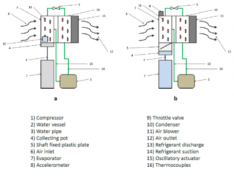
Without any of attachments, heat pump AWG has a reciprocating compressor with refrigerant R134a (1), condenser (10), evaporator (7) and throttle valve (9) as in compression vapor cycle. At first, the condensed water onto evaporator fins is collected in the collecting pot (4) under the effect of gravity, surface tension and air flow rate. Water vessel (2) 15 cm x 30 cm x 15 cm is the main water storage of system and water is transported through collecting pot to vessel through water pipe (3) by gravity. Air circulation is created by blower (11) which is located behind the condenser (10). Ambient humid air is circulated throughout evaporator to condenser, between air-inlet (6) and outlet (12). Condensation and evaporation surface temperatures are measured by thermocouples (16) which are placed on the outer surfaces of evaporator and condenser. Thermocouples, which are located on inlet, outlet, and middle tube, are fixed to pipe surface in notches which provide thermal insulation between ambient condition and pipe outer surface. In order to ensure the thermal balance for vapor compression cycle, the heat on the condenser is absorbed by the cold air that comes throughout evaporator fins. A reasonable gap is left between evaporator and condenser to avoid heat transfer and re-evaporation of generated water. Refrigerant charge had been optimized up to the compressor capacity and operating conditions before combining heat pump AWG with experimental setup.
Figure 1. Heat pump AWG equipped with different systems separately to generate mechanical effects: a) AWG with AIV; b) AWG with MIP
AWG with AIV comprises oscillatory actuator (15) generating desired frequency and vibration. The desired vibration had been applied to the system with specific frequencies. Therefore, the amount of drained water through evaporator regarding the effect of vibration is investigated. Besides, AWG with MIP is established with dc-motor and shaft fixed plastic plate (5) creating mechanical impacts on evaporator. Enda ETM 442 digital timer is directly connected to a Panasonic DC motor. The motor is activated at the desired time intervals with digital timer. Thus, a mechanical impact is imposed on the evaporator by the plate attached to the shaft. An accelerometer (8) which detects the change of acceleration during the impact period is positioned on the top of the evaporator.
2.2 Experimental procedure and measurement
Relative humidity of ambient air, dry bulb temperature of ambient air and system components, variation of acceleration regarding mechanical effect on evaporator, and amount of condensed water in water vessel are measured throughout experimental studies. Thermocouples (K-type), Cisco humidity temperature sensor and digital weighing machine are used through measurements. Further, a workstation connected to the data acquisition unit is used for data collection and processing. An accelerometer is additionally used to determine the effect of the mechanical impact on evaporator which is located on AWG with MIP.
The experiments were performed in a conditioned room which provides constant desired ambient temperature and relative humidity. Experimental setup has a similar mechanical system and working condition with in-house heat pump laundry dryer. Hence, experiments were carried out based on Europe Union EN 61121 (Tumble dryers for household use - Methods for measuring the performance) in which ambient dry bulb temperature and relative humidity were given 23°C and 55%, respectively for the test standards [28].
Throughout experimental studies, at first, baseline measurements were carried out with the heat pump AWG without any attachment. As an experimental procedure to conduct sustainable studies, since the evaporator was initially dry, it was expected that the system reached steady state conditions regarding wetness of evaporator during the first hour period. The amount of condensed water per hour (kg h-1) and energy consumption (kg kWh-1) were measured after one hour run.
Table 1. Standard deviation analysis of parameters acquired during experiments
|
Parameter |
Standard deviation |
|
Evaporator & condenser temperature |
1.02 |
|
Amount of condensate |
0.66 |
|
Power consumption |
8.89 |
|
Ambient relative humidity |
1.39 |
|
Acceleration |
1.21 |
The uncertainties that may arise from measuring instruments and environmental factors are important parameters to consider as to sustaining credibility. Standard deviation describes how the experimental data are spread in accordance with the arithmetic mean. It is desirable that the standard deviation could be relatively quite small. In this case the experimental values are closer to the mean value thereby
this indicates that the experimental data are consistent. Standard deviations of measurements acquired from experimental studies are shown in Table 1. According to standard deviation analysis, experimental measurements are considered credible and consistent.
Computational analysis of drainage through fin surface at presence of film-wise or drop-wise condensation is still a controversial issue [29]. A CFD model has been generated in order to shorten design period and examine the effects of various parameters for further studies. ANSYS Fluent 16.2 has been used to establish a numerical approach which is essentially focused on the effect of the mechanical impact on the evaporator. Three-dimensional (3D) analysis of water drainage between two adjacent fins has practically been simulated.
Air flow has been accepted as uniform in the whole slots of the evaporator fins. Hence only one slot between two adjacent fins has been considered for the simulation. Periodic boundary conditions have been applied between fins. In order to shorten time-dependent numerical calculation water drainage among adjacent fins and mitigate the effect of ongoing technical ambiguities, condensation phenomenon has not been taken into account. Amount of condensed and drained water between two adjacent fins of evaporator was determined experimentally for steady-state conditions. Total amount of drained water acquired in the experimental measurements, was divided equally and distributed uniformly throughout fin surfaces like film-wise condensate and used as the initial boundary condition in numerical model.
Transient numerical simulation of drainage of water has been realized under g = -9.81 m s-2. Numerical study is carried out to investigate applicability of mechanical impact generated by AWG with MIP for possible further evaporator designs. In the experimental study, an accelerometer is used to determine the acceleration created by the mechanical impact on evaporator. Variation of the acceleration generated by impact has been concerned as the local change of the gravity on the evaporator. Thus oscillations induced by the mechanical impact were set with a user-defined function (UDF) as an input data for the gravity. In conclusion, experimental and numerical studies have been compared as to determine the compatibility of the numerical model.
3.1 Model geometry, grid generation and grid independence
Evaporator used in experimental studies has been digitally generated with SpaceClaim. The evaporator was designed based on staggered divergent tube configuration encompasses 151 fins positioned adjacently. Since the flow between the two adjacent fins is periodic so only one interval has been considered to model geometry and flow volume.
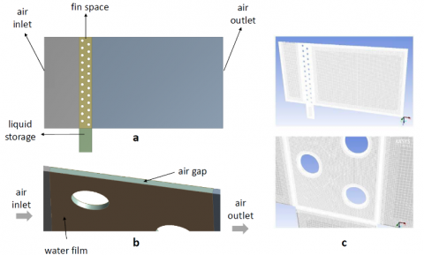
The Cutcell assembly mesh generator has been applied to generate 3D numerical solution grid of the model geometry shown in Figure 2. The computational grid has approximately 2,750,000 tetrahedral cells. Due to the examination of drainage process that has a relatively strong interaction throughout walls, implementation of inflation at boundaries is an essential factor.
Figure 2. 3D evaporator model herewith: a) side-view; b) airgap; c) grid structure
Low error rate regarding 3D grid structure is a significant parameter of numerical solution. Disorders in grid structure cause to divergences and incorrect results. Error, based on grid structure, virtually is decreased with ascent in cell numbers. Nevertheless, the more the cell number increases the time required for solution is prolonged. Therefore, various grid structures were investigated between 100,000 to 5,000,000 cells for the purpose of anticipating optimal cell number. Study for average static pressure into domain reveals that mesh independent solution can be achieved for the grid including more than 1,000,000 cells, where Y+ is set approximately 5.
3.2 Governing equations
VoF model can be used to figure out physical interaction among immiscible fluids by solving a single set of momentum equations together with a tracking method of each fluids present in the numerical domain. Continuity, momentum and energy equations for transient volume of fluid (VoF) method can be shown off as follows [30].
$\frac{\partial \rho}{\partial t}+\nabla \cdot(\rho \vec{v})=0$ (1)
$\frac{\partial}{\partial t}(\rho \vec{v})+\nabla \cdot(\rho \vec{v} \vec{v})=-\nabla p+\nabla \cdot(\overline{\overline{\tau }})+\rho \vec{g}$ (2)
$\frac{\partial}{\partial t}(\rho E)+\nabla \cdot(\vec{v}(\rho E+p))=\nabla \cdot\left[k_{e f f} \nabla T-\sum_{j} h_{j} \vec{J}_{j}+\left({{\overline{\overline{\tau }}}_{eff}} \cdot \vec{v}\right)\right]$ (3)
Change of gravity is substantial through numerical solution in order to assess mechanical impact, therefore energy equation has to be solved as transient. There are two discrete immiscible phases that are water-liquid (drained through fins) and air-gas (flows between two adjacent fins). Phase changing or transition between phases has not been considered due to on-going numerical ambiguities. Hence an explicit VoF model has been used in numerical solution with two of Eulerian phases and sharp interface modeling that solves immiscible fluids within one part of momentum equations.
VoF model mainly tracks the interfaces among phases by solving continuity equation for the volume fraction as shown in Eq. 4.
$\frac{1}{\rho_{q}}\left[\frac{\partial}{\partial t}\left(a_{q} \rho_{q}\right)+\nabla \cdot\left(a_{q} \rho_{q} \vec{v}_{q}\right)=S_{a_{q}}+\sum_{p=1}^{n}\left(\dot{m}_{p q}-\dot{m}_{q p}\right)\right]$ (4)
Instead of solving each phase separately, volume fraction equation is merely solved for secondary-phase so as to alleviate computational work. The primary-phase which is computed afterwards based in the sum of phases which is confined by 1 shown with Eq. 5.
$\sum_{q=1}^{n} a_{q}=1$ (5)
Surface tension is an inevitable issue for interaction of phases through interfaces, and can be modeled with VoF. Surface tension is a force that is merely applied to the surface due to variances of physical properties of phases. Yet the under dynamic circumstances the surface tension might be changed, the cases similar to present study can be modeled assuming a constant value. The region where the effect of surface tension is significant should mesh with quadrilateral or hexahedral [30].
To anticipate the flow regime and related parameters, Reynolds number (Re) based on hydraulic diameter (Dh) is taken into account.
$R e=\frac{U L}{v}$ (6)
$D h=\frac{U L}{v}$ (7)
In regards to heat exchanger dimensions, hydraulic diameter is $D_{h}=2.12 \mathrm{mm}$ and hereby Reynolds number is $R e \approx 150$ at where the laminar regime emerges for fluid flow. Capillary number (Ca) and Weber number (We) determine the impact of surface tension with relation based on Re.
$R e \ll 1 \quad \rightarrow \quad C a=\frac{\mu U}{\sigma}$ (8)
$R e \gg 1 \quad \rightarrow \quad W e=\frac{\rho L U^{2}}{\sigma}$ (9)
If Ca or We is greater than 1, the effect of surface tension can be ignored [38]. Since $R e \approx 150$, Weber number is therefore the dimensionless parameter to scrutinize surface tension among phases calculated as $We \approx 0.2$. The continuum surface force (CSF) and the continuum surface stress (CSS) are surface tension models defined in commercial solver ANSYS Fluent [30]. In this study, the continuum surface force (CSF) has been used that provides a reliable model to present case. Surface tension coefficient between water and air is expressed 0.072 N m-1 at room condition [31]. Pressure jump through surface connotes surface tension and can be written as below if there are only two phases in the finite volume. The force in accordance with surface tension is added to momentum equation as a source term.
3.3 Modeling approach
The numerical analysis has been carried out at transient conditions in three-dimensional space. The flow volume is kept wide enough at the inlet and outlet so as to investigate possible flow separations after fins. VOF method has been used to model interaction between air and water phases. Fin wall material has been taken as aluminum as used worldwide. Temperature is specified 23°C constant through volume. Air flow conditions are defined with velocity inlet conditions. Air is intended incompressible ideal gas and velocity distributed over the evaporator inlet uniformly with the value of 0.1 m s-1. Total amount of drained water measured during experiments has been divided equally and distributed - patched through fin surfaces like film-wise in numerical model as the initial boundary condition. No turbulence model is implemented for viscous flow solution due to low Reynolds number. SIMPLE (Semi-Implicit Method for Pressure-Linked Equations) algorithm has been selected for the discretization of pressure-velocity coupling. Second order upwind spatial discretization has been defined to solve momentum and energy equations. The residuals have at least been taken 0.0001 for continuity and momentum. Compressive method offered by commercial solves has been selected to define interphase between air and water.
Water drainage between two adjacent fins has been simulated so as to come across a numerical solution to foresee applicability of mechanical impact. Initially, transient numerical simulation of drainage of water under constant gravity g=-9.81 m s-2 has been carried out without any of mechanical effects as a baseline system. Following baseline analysis, a secondary numerical study has been prompted in which vibrations generated due to mechanical impact are implied by a UDF. Notably, being mentioned before previously, an accelerometer is used to determine the effect of the mechanical impact on evaporator during experimental study. The change in acceleration is assumed as the local change in gravity in which environment the evaporator is present. Hence the change in acceleration which is mainly oscillations driven by mechanical impact is set as input data for the numerical analysis.
4.1 Experimental results
Experimental studies have been carried out in Arcelik A.S. Central RD laboratories at ambient dry bulb temperature 23°C and relative humidity 55%. Comparison among heat pump AWG systems has been performed in accordance with amount of condensed water per hour. Vibration frequency of oscillator in AWG with AIV has been considered as 75 Hz. The period of vibration has been taken into account with various ranges of run and standby time. Run-time (on-time) is held constant around 20 seconds. 20, 40, 60 and 80 seconds are considered as standby-time (off-time). For AWG with MIP, 10 seconds run-time and 5 seconds standby time have been applied permanently throughout experiments. Variation of condensed water among modified systems has been compared to the amount of condensed water by heat pump AWG system which has not any auxiliary structure to amplify drainage performance. In Table 2, experimental setups are clarified with related abbreviations which also includes run- and standby-times. Additionally, cooling capacity of compressor is directly associated with amount of condensed water regarding heat pump cycle. The changes for evaporation temperature and cooling capacity of compressor have a similar trend due to working mechanism of reciprocating compressor and heat pump cycle. Cooling capacity of compressor rises while evaporation temperature increases thereby total amount of condensed water increases.
Experimental results indicate that 11.6% increase is achieved in average on the total amount of condensation by AWG with AIV according to comparison against baseline AWG. Results also shows standby-period which varies between 20 to 80 seconds has no remarkable changes on amount of condensation. Furthermore, 18% increase is accomplished by AWG with MIP that may be specified as maximum amount of condensation among all setups realized in the scope of the present study. Table 2 illustrates all the experimental results have been obtained with related evaporator temperatures. An increase in evaporation temperature is a sign of the increase in the amount of condensation in accordance with cooling capacity. Due to the pressure losses through the passage of evaporator at where refrigerant flows, an ascent is observed for the surface temperature of the evaporator thereby changing the dryness fraction. The cooling capacity and the power consumption of the compressor used in the experimental study are around 1250Wh and 500Wh respectively at ASHRAE conditions (+7.2°C evaporation temperature) for high-back-pressure compressors.
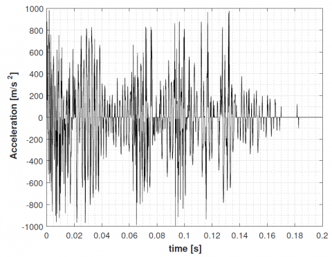
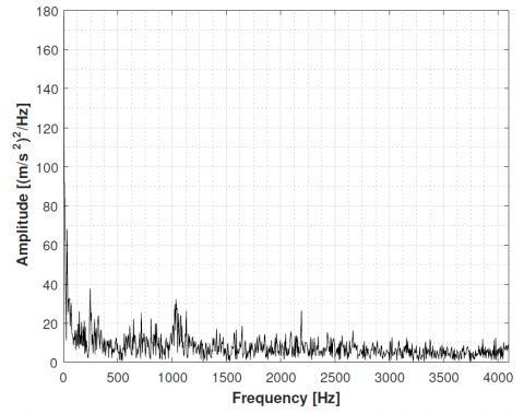
In order to provide a credible sampling frequency, period of subsequent measurements was kept relatively small. Hence the measurement time step is set to 1.22 × 10⁻⁴ in terms of second when the analog signal is converted into a digital signal. Total duration of impact has been detected close to 0.2 seconds. The change of acceleration and Fast Fourier Transform (FFT) analysis are illustrated in Figure 3 and Figure 4, respectively. The FFT analysis, which transforms one-dimensional ordered linear data into the frequency domain in order to assess the acquired data, is realized by Tecplot 360 visualization tool based on FFTW software library [32].
Table 2. Increase in condensation for different cases with various run- and standby-times compared to baseline AWG without any of attachments, and temperature change through inlet, middle and outlet of evaporator
|
System |
Run/ (sec) |
Increase in condensation (%) |
Evaporator temperature: inlet, middle, outlet (°C) |
|
No attachment |
- |
- |
5.4, 4,9, 4.5 |
|
AIV |
20/20 |
12.6 |
7.2, 6.6, 6.1 |
|
AIV |
20/40 |
12.5 |
7.2, 6.5, 6.0 |
|
AIV |
20/60 |
10.6 |
6.6, 6.1, 5.5 |
|
AIV |
20/80 |
10.8 |
6.7, 6.2, 5.7 |
|
MIP |
10/5 |
18 |
8.1, 7.6, 7.1 |
Figure 3. Time-dependent change of acceleration
Figure 4. Single-sided amplitude spectrum of signal in time domain
4.2 Numerical results
Numerical studies have been carried out to generate a convenient model to investigate fin plate heat exchanger within various dimensions at the presence of mechanical impact. Analysis of water drainage between two adjacent fins has intentionally been carried out. Total amount of drained water according to experimental result has been divided equally and distributed - patched through fin surfaces like film-wise condensation in numerical model as an initial boundary condition. The simulation results have been compared to the experimental ones afterwards.
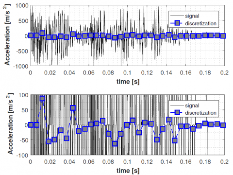
4.2.1 Discretization of acceleration
The mechanical effect generated by MIP in terms of acceleration was sampled by accelerometer during experimental study. This collected data hereby facilitates a boundary condition mimicking the impact that the evaporator encounters. Since relatively high sampling frequency provides a huge amount of data collected throughout processing, discretization was required so as to reduce total number of samplings by having local means. Implementing all sampled data throughout experimental study results in an enormous computational effort and redundant task whilst local means give applicable outcomes.
Several time steps have been assessed to find appropriate range to enable a proper discretization procedure in time domain without compromise on accuracy. Having been compared widely, the time step for discretization has intentionally been selected 6.2 × 10⁻³ sec which is conveyed in Figure 5. Local mean of accelerations is calculated among each time steps where total duration for physical incident takes 0.2 sec. Local mean of accelerations, which are then summed with gravity to imply the effect of mechanical impact, are inserted with user-defined function.
Figure 5. Discretization of acquired signal by means where the time step selected 6.2 × 10⁻³
The mean value of whole signal is -11.14 m s-2 in which sampling frequency was 8200 Hz. Discretized acceleration is a relative and dimensional quantity. For instance, being zero means there is no change of gravity which is specified as 9.81 m s-2 in y-axis beforehand.
4.2.2 Water drainage simulation
The effect of acceleration in terms of gravity generated by AWG with MIP has been investigated via numerical method. Variation of discretized acceleration through the evaporator is directly interrelated with gravity. For this purpose, discretized acceleration change has been assumed and applied as the change of gravity within UDF.
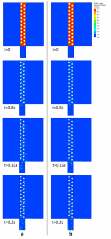
At first, numerical analyze has been carried out with constant gravity 9.81 m s-2 and the amount of drained water in 0.2 sec has been determined as baseline. Following the baseline, numerical analyze has been renewed to simulate mechanical impact which is applied to the evaporator in 0.2 sec. The acceleration induced to the evaporator has been implemented to the system as the change of gravity. In that case, the total mass of water collected in one hour increases 15% approximately. In Figure 6, time dependent volume changes of liquid (water) and gas (air) phases are illustrated with water volume fraction contours. Numerical results with constant gravity g = 9.81 m s-2 is represented by Figure 6a whilst Figure 6b shows the approach aimed by the present study based variable gravity concerning local mean of acceleration. Tube layout for the heat exchanger in the present study is staggered tube banks whereas an arrangement of tubes in a zigzag formation are set to amplify heat transfer, thereby phase change. Once it may relatively be extracted from Figure 6, staggered tube banks also adversely affect water drainage process interrupting water streams through condensate collecting pot. In order to prevail over this incident, different arrangements can numerically be investigated to find optimal design criterion considering both heat and mass transfer. The heat exchanger in the present study was designed by using commercial design and optimization of air-cooled heat exchanger tool mainly concerning heat transfer side [33]. Moreover, a considerable amount of condensate is also swept forward due to continuous air circulation throughout heat pump cycle. Yet a broader condensate collecting pot might be attached to the system, structural restrictions prevent the designers currently to refrain this condensate lost. All in all, CFD study carried out herewith boundary conditions, which has a reasonable agreement with experimental study, facilitates a reliable numerical study so as to investigate water drainage performance of tube bank heat exchangers.
Figure 6. Time-dependent change of volume fraction liquid water: a) constant gravity; b) variable gravity with UDF
Water drainage performance of heat pump AWG has been examined by influencing evaporator mechanically. Aside from AWG without any attachment, the effect of mechanical impact (MIP) and vibration (AIV) have respectively been assessed based on collected condensate underneath evaporator. Experimental results indicate that 11.6% increase has been achieved in average on the total amount of condensation by AWG with AIV according to comparison against baseline AWG. Likewise, 18% increase has been succeeded by AWG with MIP that may be specified as maximum amount of condensation among all setups realized in the scope of the present study. Results clearly indicate that mechanically influenced system bring evident increases. A numerical study has also been prompted to illustrate water drainage performance of evaporator at AWG with MIP. To come up with a quick and cost-effective method, condensation was purposefully neglected in which a film-wise condensation was assumed instead. Comparison shows that numerical approach can be considered in order to foresee water drainage performance of evaporator under mechanical influence before settling up an experimental campaign. Furthermore, several improvements can still be needed to achieve a more efficient water drainage process. Vibration frequencies, impact frequencies and run standby intervals in different ranges should be examined in detail to maximize system efficiency in a broad perspective on the experimental side. On the numerical side, it would be appropriate to conduct a numerical study which investigates the effect of mechanical effects by modeling condensation. A numerical study examining water drainage process for different tube bank arrangements might even be beneficial to increase the amount of condensate collected into pot.
The authors gratefully acknowledge support for Arcelik A.S. Research and Development Center.
|
a |
acceleration, m. s-2 |
|
|
A |
heat transfer area, m-2 |
|
|
Ca |
Capillary number |
|
|
D |
diameter, m |
|
|
g |
gravitational acceleration, m.s-2 |
|
|
Hz |
hertz, Hz |
|
|
kg |
kilogram, kg |
|
|
kWh |
kilowatt-hours, kW.h |
|
|
k |
thermal conductivity, W.m-1. K-1 |
|
|
L |
depth of heat transfer side along the fin |
|
|
m |
amount of condensate, kg. |
|
|
P |
Power, P. |
|
|
Re |
Reynolds number |
|
|
RH |
relative humidity, %. |
|
|
S |
standard deviation |
|
|
T |
temperature, ℃ |
|
|
U |
free stream velocity, m.s-1 |
|
|
We |
Weber number |
|
|
AWG |
Atmospheric Water Generator |
|
|
CFD |
Computational Fluid Dynamics |
|
|
CSF |
Continuum Surface Force |
|
|
CSS |
Continuum Surface Stress |
|
|
DC |
Direct Current |
|
|
FFT |
Fast Fourier Transform |
|
|
FFTW |
Fastest Fourier Transform in the West |
|
|
MIPC |
Mechanical Impact Plate Combined |
|
|
OC |
Oscillator Combined |
|
|
PLC |
Programmable Logic Controller |
|
|
UDF |
User Defined Function |
|
|
VoF |
Volume of Fluid |
|
|
Greek symbols |
||
|
ρ |
density, kg. m-3 |
|
|
σ |
surface tension, N. m-1 |
|
|
υ |
kinematic viscosity, m2.s-1 |
|
|
µ |
dynamic viscosity, kg. m-1.s-1 |
|
|
Ɵ |
contact angle |
|
|
τ |
stress tensor |
|
|
Subscripts |
|
|
|
h |
hydroulic |
|
|
eff |
effective |
|
|
w |
water |
|
|
pq |
mass transfer from phase p to q |
|
|
qp |
mass transfer from phase q to p |
|
[1] WWAP (United Nations World Water Assessment Programme)/UN-Water. (2018). The United Nations World Water Development Report 2018: Nature-Based Solutions for Water. Paris, UNESCO.
[2] Mirandola, A., Lorenzini, E. (2016). Energy, environment and climate: From the past to the future. International Journal of Heat and Technology, 34(2): 159-164. https://doi.org/10.18280/ijht.340201
[3] Liu, H., Yousaf, K., Chen, K., Fan, R., Liu, J., Soomro, S. (2018). Design and thermal analysis of an air source heat pump dryer for food drying. Sustainability, 10(9): 3216. https://doi.org/10.3390/su10093216
[4] Ganesan, P., Vanaki, S.M., Thoo, K.K., Chin, W.M. (2016). Air-side heat transfer characteristics of hydrophobic and super-hydrophobic fin surfaces in heat exchangers: A review. International Communications in Heat and Mass Transfer, 74: 27-35. https://doi.org/10.1016/j.icheatmasstransfer.2016.02.017
[5] Choi, C., Kim, M. (2011). Wettability Effects on Heat Transfer, Two Phase Flow, Phase Change and Numerical Modeling, ISBN: 978-953-307-584-6, InTech, Available from: http://www.intechopen.com/books/two-phase-flow-phase-change-and-numerical-modeling/wettability-effectson-heat-transfer
[6] Kim, M.H., Bullard, C.W. (2002). Air-side performance of brazed aluminum heat exchangers under dehumidifying conditions. International Journal of Refrigeration, 25(7): 924-34. https://doi.org/10.1016/S0140-7007(01)00106-2
[7] Sung, S.K., Suh, S.H., Kim, D.W. (2008). Characteristics of cooling water fouling in a heat exchange system. Journal of Mechanical Science and Technology, 22(8): 1568-75. https://doi.org/10.1007/s12206-008-0422-9
[8] Fernández-Seara, J., Sieres, J. (2006). Ammonia–water absorption refrigeration systems with flooded evaporators. Applied Thermal Engineering, 26(17-18): 2236-46. https://doi.org/10.1016/j.applthermaleng.2006.03.011
[9] Wong, S.C., Lin, Y.C., Liou, J.H. (2012). Visualization and evaporator resistance measurement in heat pipes charged with water, methanol or acetone. International Journal of Thermal Sciences, 52: 154-60. https://doi.org/10.1016/j.ijthermalsci.2011.09.020
[10] Zhou, X., Zhao, F., Guo, Y., Zhang, Y., Yu, G. (2018). A hydrogel-based antifouling solar evaporator for highly efficient water desalination. Energy & Environmental Science, 11(8): 1985-92. https://doi.org/10.1039/C8EE00567B
[11] Thimmaiah, P.C., Sharafian, A., Rouhani, M., Huttema, W., Bahrami, M. (2017). Evaluation of low-pressure flooded evaporator performance for adsorption chillers. Energy, 122: 144-58. https://doi.org/10.1016/j.energy.2017.01.085
[12] Bergmair, D., Metz, S.J., de Lange, H.C., van Steenhoven, A.A. (2014). System analysis of membrane facilitated water generation from air humidity. Desalination, 339: 26-33. https://doi.org/10.1016/j.desal.2014.02.007
[13] Korte, C., Jacobi, A.M. (2001). Condensate retention effects on the performance of plain-fin-and-tube heat exchangers: Retention data and modeling. Journal of Heat Transfer, 123: 926-936. https://doi.org/10.1115/1.1391276
[14] Chavan, S., Cha, H., Orejon, D., Nawaz, K., Singla, N., Yeung, Y.F., Park, D., Kang, D.H., Chang, Y.J., Takata, Y., Miljkovic, N. (2016). Heat transfer through a condensate droplet on hydrophobic and nanostructured superhydrophobic surfaces. Langmuir, 32(31): 7774-87. https://doi.org/10.1021/acs.langmuir.6b01903
[15] Tu, Y.D., Wang, R.Z., Ge, T.S., Zheng, X. (2017). Comfortable, high-efficiency heat pump with desiccant-coated, water-sorbing heat exchangers. Scientific Reports, 7: 40437. https://doi.org/10.1038/srep40437
[16] Solomon A.B., Daniel, V.A., Ramachandran, K., Pillai, B.C., Renjith Singh, R., Sharifpur. M., Meyer, J.P. (2017). Performance enhancement of a two-phase closed thermosiphon with a thin porous copper coating. International Communications in Heat and Mass Transfer, 82: 9-19. https://doi.org/10.1016/j.icheatmasstransfer.2017.02.001
[17] Cheng, C.H., Chen, H.N., Aung, W. (1997). Experimental study of the effect of transverse oscillation on convection heat transfer from a circular cylinder. Journal of Heat Transfer, 119(3): 474. https://doi.org/10.1115/1.2824121
[18] Aldana, L., Chochol, A., Ferraro, T. (2008). Compositions and methods for eliminating and preventing vehicle odors, WO2008/025168Al.
[19] Max, M.D. (2010). Atmospheric moisture harvesting. US2010/0307181A1.
[20] Tan, H., Xu, G., Tao, T., Sun, X., Yao, W. (2015). Experimental investigation on the defrosting performance of a finned-tube evaporator using intermittent ultrasonic vibration. Applied Energy, 158: 220-32. https://doi.org/10.1016/j.apenergy.2015.08.072
[21] Wang, D., Tao, T., Xu, G., Luo, A., Kang, S. (2012) Experimental study on frosting suppression for a finned-tube evaporator using ultrasonic vibration. Experimental Thermal and Fluid Science, 36: 1-11. https://doi.org/10.1016/j.expthermflusci.2011.03.002
[22] Li, D., Chen, Z. (2014). Experimental study on instantaneously shedding frozen water droplets from cold vertical surface by ultrasonic vibration. Experimental Thermal and Fluid Science, 53: 17-25. https://doi.org/10.1016/j.expthermflusci.2013.10.005
[23] Tan, H., Tao, T., Xu, G., Zhang, S., Wang, D., Luo, X. (2014). Experimental study on defrosting mechanism of intermittent ultrasonic resonance for a finned-tube evaporator. Experimental Thermal and Fluid Science, 52: 308-17. https://doi.org/10.1016/j.expthermflusci.2013.10.006
[24] Tan, H., Xu, G., Tao, T., Zhang, S., Luo, A. (2016). Investigation on the ultrasonic propagation mechanism and its application on air-source heat pump defrosting. Applied Thermal Engineering, 107: 479-92. https://doi.org/10.1016/j.applthermaleng.2016.06.185
[25] Cole, J.T. (2007). Method and apparatus for removing moisture from evaporator coils. US007269967B2.
[26] Wu, X.M., Webb, R.L. (2001). Investigation of the possibility of frost release from a cold surface. Experimental Thermal and Fluid Science, 24(3-4): 151-6. https://doi.org/10.1016/S0894-1777(01)00045-0
[27] Qi, Z. (2013). Water retention and drainage on air side of heat exchangers—A review. Renewable and Sustainable Energy Reviews, 28: 1-10. https://doi.org/10.1016/j.rser.2013.07.014
[28] Tumble dryers for household use - Methods for measuring the performance (IEC 61121:2013). (2013). European Standard EN 61121.
[29] Arkles, B. (2006). Hydrophobicity, hydrophilicity and silanes article. Paint and Coatings Industry, 22(10): 114.
[30] ANSYS, Inc. (2013). ANSYS Fluent Theory Guide, 275 Technology Drive Canonsburg, PA 15317.
[31] Bernardin, J.D., Mudawar, I., Walsh, C.B., Franses, E.I. (1997). Contact angle temperature dependence for water droplets on practical aluminum surfaces. International Journal of Heat and Mass Transfer, 40(5): 1017-33. https://doi.org/10.1016/0017-9310(96)00184-6
[32] Frigo, M., Johnson, S.G. (2005). The design and implementation of FFTW3. Proceedings of the IEEE, 93(2): 216-31. https://doi.org/10.1109/jproc.2004.840301
[33] Jiang, H., Aute, V., Radermacher, R. (2006). Coildesigner: A general purpose simulation and design tool for air-to-refrigerant heat exchangers. International Journal of Refrigeration, 29: 601-610. https://doi.org/10.1016/j.ijrefrig.2005.09.019