Krishna Kant Dwivedi* | Malay Kumar Karmakar | Achintya Kumar Pramanick | Pradip Kumar Chatterjee
© 2019 IIETA. This article is published by IIETA and is licensed under the CC BY 4.0 license (http://creativecommons.org/licenses/by/4.0/).
OPEN ACCESS
In this paper a brief review on hydrodynamic characteristic of coal gasification is presented. Firstly an introduction of hydrodynamics then parameters related to hydrodynamics is discussed. In the last several decades Coal gasification is an important method to use of coal resources. The hydrodynamic characteristics have an important role to design of Circulating fluidized bed gasifiers. Circulating fluidized bed (CFB) gasifiers widely use due to their high reaction rates and high thermal efficiency. The present study includes some hydrodynamics properties of coal gasification such as effect of pressure and temperature, solid hold up, solid circulation rate, gas-solid contact, particle residency time, coal feeding rate and coal feeding position. During the brief review on hydrodynamics characteristics of coal each section of CFBs such as riser, cyclone, stand-pipe and loop seal have been considered.
circulating fluidized bed, Riser, loop-seal, hydrodynamics, gasification
The gasification of coal through circulating fluidized bed gasifier became more important for various industrial applications such as chemical, power-generation and petrochemical since last few decades. Commonly, circulating fluidized beds have a lot of application in the field of environment and energy industries for the purpose of gasification of coal. Sulphur capture and low emission of NOx also an important factor in circulating fluidized bed gasification process [1-5]. During the coal gasification in CFB, fuels such as- coal, biomass converts into valuable gas known as syngas. In gasification the hydrodynamic condition, is an important factor to the CFB process as it provides high slip velocity for the gas and the solids [6-7]. The hydrodynamics behaviour analysis is the key point for improving the performance and design of CFB. A circulating fluidized bed system comprises of a riser, a gas solid separating unit and a down-comer. In this system the mixture of gas-solid moves upward and passes through the separator where solid particles get separated from carrier gas and recycled back to the riser, the gasifier, through the down-comer [8-10]. Generally, in coal gasification in CFB unit, the hydrodynamic study of CFB reactor is a very important aspect while carrying out research since various parameters of gas-solid movement, gas velocity, solid movement, solidity, reactor geometry, etc., play a determining role in its conversion efficiency [11-12]. Different factors during the coal gasification in CFB such as gas velocity, solid circulation rate, solids characteristics, volume of solids and the system geometry provides special hydrodynamic conditions. In a CFB unit, considering riser section in which solid particles are fluidized and a cyclone where particles are disengaged from gas and a return leg for return to the riser. The behaviour of the particles in fluidized beds depends not only on the flow parameters but also strongly upon the particle characteristics as well. Mostly in circulating fluidized bed units, particles are fed from the down-comer through a fluidized angled standpipe in to a fluidized annular region in the engagement section. Motive air enters the engagement section through a central pipe. Particles are entrained by the motive air and are transported upward through the riser to an annular disengagement section [13]. An aluminium impact plate at the top of the disengagement section initially separates the gas-particles mixture. The separated particles settle into an annular fluidized bed, which empties into the down-comer via a fluidized angled standpipe. The air exits the disengagement section and passes through cyclone separator to remove particles that were not separated in the disengagement section. The axial hydrodynamics behaviour for in liquid-solid CFB system studied [14]. They found that liquid-solid CFB system can be divided in two sections first is the initial circulating fluidized bed zone and second is fully developed circulating fluidized bed system zone. Therefore, during the experiments the fluidization of liquid-solid system is controlled by the flow rate of liquid substances. The behaviour of the particles in fluidized beds depends not only on the flow parameters but strongly upon the particle characteristics as well. Mostly in circulating fluidized bed units, Particles are fed from the down comer through a fluidized angled standpipe into a fluidized annular region in the engagement section. Motive air enters the engagement section through a central pipe. Particles are entrained by the motive air and are transported upward through the riser to an annular disengagement section. An aluminium impact plate at the top of the disengagement section initially separates the gas-particle mixture. The separated particles settle into an annular fluidized bed, which empties into the down-comer via a fluidized angled standpipe. The air exits the disengagement section and passes through cyclone separators to remove particles that were not separated in the disengagement section. So during the experiments the fluidization of liquid-solid system can be controlled by the liquid flow rate. The hydrodynamics study for binary mixture of solid in triple bed combined circulating fluidized bed system experiment has been carried out [15] and explained about the characteristics with high mass flux. They studied about the flow behaviour of silica sand with coal char substitute. This results that most of the particles successfully circulated without any segregation in the CFBs units. Earlier stud justified that voidage for dense suspension up flow conditions are near the wall than in the core [16]. Hydrodynamics of CFB system has an on the reactor design and it has a great significant in industry. So to find out the response of system for a circulating fluidized bed unit some factors affects the system performance for example solids holdup and solids circulation rate.
2.1 Gas-solid contact in riser section
Hydrodynamic is an important way to explain the gas–solid flow behaviour in riser section. Basically riser is an important part for a CFB system to study about gas-solid contact during gasification process. Riser is able to pass different flow regimes and also capable to carry more heat and mass transfer [17]. In fluidization system solid particles are transported into a fluid through suspension in a gas or liquid. Some previous research articles studied on the effect of riser exit geometry on the hydrodynamic of CFB system. Outlet geometry of CFB riser mainly affects the particle flow and solid back-mixing inside the riser section. It was noticed that in a CFB unit, different flow regimes occur in riser can be divided in three different regimes based on solid behaviour: the core, annulus and acceleration zones. The first region, the core, covers more area of riser where upward flow of gas and solids takes place. Second is the annulus which concentrically bound by the wall of the CFB [18-19]. In this region the gas and solids flow downward. The suspension density is normally higher in the core region. Third region is acceleration zone, located at the base of the reactor. For the analysis of gas-solid contact there are several computational fluid dynamic (CFD) methods where most of them are Eulerian-Eulerian (EE) and Lagrangian-Eulerian (LE) analysis to simulate the gas-solid flow behaviour inside riser section. CFD-DEM is a coupled approach to simulate the fluid-particle interaction. Discrete Element Method (DEM) employed to model the granular particle system and the Computational Fluid Dynamics is used to simulate the fluid flow. Now a day’s numerical simulation has become the primary means to study the flow behaviour characteristics of fluidized bed system. DEM basically belongs to the deterministic model of the Euler–Lagrange method, which can describe the translational and rotational motion of the particles and also can be considered as a kind of soft sphere model. 2D and 3D simulation has a vital role in the study of solid-gas behaviour in the riser section. The grid size has an important role to establish the flow behaviour of gas-solid inside the riser section. According to the rule of thumb the grid size is approximately 10-particle diameter. In any circulating fluidized bed system the rate of gas-solid contact depends on the operating conditions and the size of particle used in CFB [44]. Many researchers [20-21] also focused on numerical study on gas-solid contact during gasification process. Energy minimization multi scale model (EMMS) explain about heterogeneous nature of gas-solid fluidization and calculate the drag using the parameter like solid mass flux and superficial velocity. Many previous researchers [22-23] explained about EMMS model. In case if the superficial velocity of gas is more than the transport velocity then gas-solid disengagement takes place and gas phase predominance starts. The EMMS model basically considers the particle acceleration and also includes the effective interface reactions and divides the multiphase flow regime in to three phases: the dense, dilute and the interaction phase. This model can calculate the drag using the parameter like solid mass flux and superficial velocity. Therefore, if the superficial velocity of (U) is more than the transport velocity, then gas-solid will be dominated by the gas-phase and the solid particles transported successfully. So in case if the gas flow rate is weak, particle cannot be suspended by the drag force. The particle suspension also depends on gas flow inside the riser section. In case if the gas flow is weak than the effect of drag force on the particle cannot be taken place. Some previous investigations [24] used the basic governing Eqns. (1) & (2) for mass conservation of the gas and solid phase.
$\frac{\partial}{\partial \mathrm{t}}\left(\mathcal{E}_{\mathrm{g}} \rho_{\mathrm{g}}\right)+\nabla \cdot\left(\mathcal{E}_{\mathrm{g}} \cdot \rho_{\mathrm{g}} \cdot \mathrm{V}_{\mathrm{g}}\right)=0, \sin ^{-1} \theta$ (1)
$\frac{\partial}{\partial \mathrm{t}}\left(\mathcal{E}_{\mathrm{s}} \rho_{\mathrm{s}}\right)+\nabla \cdot\left(\mathcal{E}_{\mathrm{g}} \cdot \rho_{\mathrm{g}} \cdot \mathrm{v}_{\mathrm{g}}\right)=0$ (2)
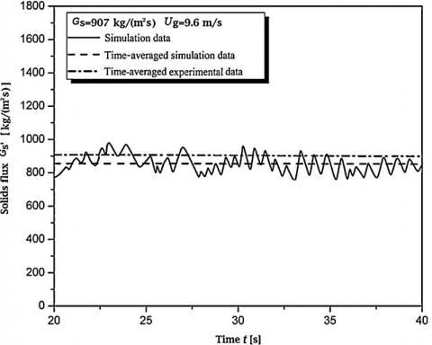
In Eq. (2) sin-1 θ represent the value of granular temperature. We can also measure solid flux to determine the gas solid contact inside the riser section. By using solid flux measurement apparatus and simulated data compared with experimental data, we can test the simulation quality as shown in Figure 1 [24].
Figure 1. Calculation of solid flux
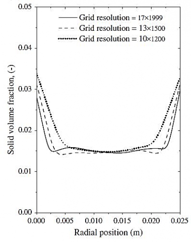
In case of downcomer it is also an important part to calculate the gas-solid contact inside CFBs. Basically downcomer describes the dynamic phenomena of the particle. The hydrodynamic properties of CFB in the downcomer is studied and explained by using computational fluid dynamics [25]. Downcomer is simulated by using Eulerian method with kinetic theory of granular flow (KTGF). In this measurement, the mass conservation equation is used as explained in Equation (1). Earlier studies [26] focus about gas-solid flow behaviour by using new combustor chamber in a scaled down cold unit. They have used computational particle fluid dynamics (CPFD) to analyse the gas-solid flow behaviour. Basically the numerical simulation approach provides a new and efficient tool to study the gas-solid hydrodynamics in circulating fluidized bed system. In this way CPFD is a method to examine the gas-solid flow in any CFB system. The commercial Barracuda-CPFD software can be used to simulate the reactor’s behaviour. This is an advanced math-based computational particle-fluid dynamics (CPFD) tool developed for efficient simulation of dense-phase fluidization in industry-scale units. It is found that the solid volume fraction inside the central section is lower as compared to near wall section. Solid concentration also continuously decreases in the bottom side but the gas-solid mixing in the bed increases continuously [27]. The discontinued gas-solid mixing behaviour affects the coal gasification. The gas-solid flow rate in term of pressure measurement was also studied in this work. By using two fluid model (TFM) the gas-solid flow or gas-solid contact inside riser in a CFB can be calculated. Basically two fluid model (TFM) coupled with KTFG gives the simulation of fluidization. Two fluid model describe the gas-solid motion with in a CFB system for both the gas and solid phase. So before knowing about the solid phase by using continuum model, study about the collisions occurring between particles in the particulate phase is essential. The kinetic theory of granular flow helps to finding out the gas-solid flow behaviour and can be used to define the solid phase properties in the two fluid model or gas-solid phase model and also may be used to compute the solid phase properties [28]. Kinetic theory of granular flow provides the certain flow condition, collisions between the particle which provide the full mechanism for the transport of properties such as momentum and energy. The main use of kinetic theory of granular flow is to obtain the transport balance equation for relevant hydrodynamic moments such as mass, momentum and energy-density along with some transport properties such as shear viscosity and thermal conductivity. Earlier research [29] used kinetic theory of granular flow to analyse the gas-solid contact behaviour in riser section. It is found that there is some solid shear viscosity effect on the flow prediction inside riser section with different solid circulation rate. Boundary conditions of solid-gas play vital role to predict the behaviour of solid-gas flow. Figure 2 shows the radial profile of the mean solid volume fraction at 2 m height and explains about the grid resolution along the height of the riser.
Figure 2. Effect of different grid resolution
The gas-solid contact efficiency can be estimated by using heat transfer measurement method through Eq. (3).
CpgρgUg A(Tg,1 – Tg,2) = hgs a(Tg - Tp)AΔZ (3)
In the above equation left hand side denotes the driving force for internal heat transfer in the system for finding out the gas-solid contact efficiency. Many researchers [30-32] examined about influence of temperature on hydrodynamic of CFB. Generally high temperature of coal gasification process affects some parameter such as minimum fluidization velocity and minimum fluidization voidage. Normally density of gas is inversely proportional to its absolute temperature, so it will decrease with increasing temperature. Increasing temperature on the other hand leads to dominance of inertial forces over viscous forces and also causes to decreasing the gas density. During gasification reaction heat of combustion is transferred from gas-solid mixture to water cooled surfaces in the wall. Therefore, it is necessary to know about influence of temperature on gasification process. Increase of temperature also increases the reaction rate for gasification resulting in formation of more combustible gases, which decreases the yield of char and liquids. Gas-contact efficiency also has an important role to understand the design of CFB reactors. It is affected by many parameters such as superficial gas velocity, solid circulation rate, solidity, etc. Previous study [33] gives expression for gas contact efficiency (Egs) as shown in Equation 4.
$\mathrm{E}_{\mathrm{gs}}=\frac{Q_{g}-Q_{g s}\left(1-T_{r}\right)}{Q_{g}}$ (4)
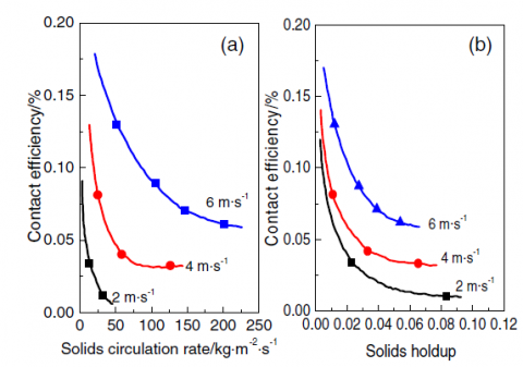
Figure 3(a) & 3(b) shows the properties of contact efficiency inside riser section with respect to solid circulation rate and solid hold up respectively.
Figure 3. Contact efficiency in riser section
It is concluded that with increasing solid holdup the contact efficiency becomes less [34]. Parametric design is also an important part to analyse the hydrodynamic behaviour in CFB. Some authors have studied the parametric design of circulating fluidization bed to predict the hydrodynamic behaviour inside the riser section. Hence the statistical model was compared and verified with experimental data and then the hydrodynamic of CFB is calculated in terms of solid circulation rate and solid holdup. Compared with circulating fluidized bed (CFBs) hydrodynamic studies, solid hold-up and solid circulation rate have received more attention. In the CFB gasification of coal, solid-holdup and solid circulation rate still being commonly treated as the parameters determining the hydrodynamic of circulating fluidized bed with valve controlled solid circulation in the riser. Solid-holdup decreases when it is accelerated by the high velocity gas stream [35]. As explained above in the gas-solid contact efficiency also helps to justify the hydrodynamic characteristic of CFB system. So basically CFB operating regimes depends on the parameters, such as, solid-holdup, solid circulation rate and gas-solid contact efficiency. The gas-solid contact behaviour during coal gasification in circulating fluidized bed is summarised in Table 1.
Table 1. Gas-solid contact behaviour analysis
|
Model |
Riser height/diameter (m) |
Pressure |
Ref. |
|
CFB unit |
20/0.012 |
0-10 kPa |
50 |
|
CFB unit |
8.85/0.127 |
116 Pa |
4 |
|
Cold model of CFB unit |
8.0/0.16 |
0-5 kPa |
46 |
|
Cold model dual fluidized bed |
3/0.025 |
0-10 kPa |
29 |
Basically particle residence time relates the mass flows outside the riser. Generally in any chemical reactors particle residence time can be calculated by injecting a tracer at the inlet and the tracer concentration with the effluent stream. So the average residence time of solid also can be calculated by riser outlet condition. Normally the riser exits and cyclone inlet connected with horizontal pipe. When gas and solids moving from vertical riser, particle accelerates along the horizontal pipe along with gas. Previous study on hydrodynamic of CFB system, it was noticed that, the solid concentration inside the CFB riser was very low and it was mainly near to the crossover. In other hand particle residence time depends on other parameters of CFB for example length of riser section and superficial gas velocity. In previous research [36] derived an expression for particle residence time, riser length divided by the superficial riser gas velocity normalized by a ratio of solid concentration in the riser outlet and the riser itself. Particle residence time means when solid particle passes through riser section, the residence time is a measure of how much time the particle spends in it. The main variable affecting the particle residence time in circulating fluidized bed system is superficial velocity and minimum fluidization velocities of solids. Increasing the fluidization velocity decreases the residence time due to the increases in the bubble velocity. With increasing solid circulation rate, the residence time decreases exponentially. So the time spent by the particle in the gasifier strongly depends on the mass turn over. Equation (5) shows the relation for particle residence time in the riser section [37].
$\mathrm{T}_{\mathrm{r}}=\frac{M_{r}}{M_{S, \text {out}}}=\frac{\rho_{p}(1-\varepsilon \mathrm{r}) A_{r s} \Delta h_{r s}}{\rho_{S}\left(1-\varepsilon_{c o}\right) A_{c o} U_{p, c o}}=\frac{\left(1-\varepsilon_{r}\right) A_{r s} \Delta h_{r}}{\left(1-\varepsilon_{c o}\right) A_{c o} U_{g, c o}}$ (5)
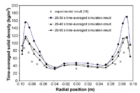
In case of gas molecules the residence time in different reactors like chemical reactor and plug flow reactor can be determined by injecting a tracer on inlet side and after that as a function of time the concentration of tracer in the effluent can be analysed. Riser outlet condition also provide the particle residence time. Considering riser section, its design can greatly enhance the reaction characteristics. Riser outlet condition play vital role to examine the particle residence time. Some previous studies [38] justified that particle residence time also depends on riser outlet conditions such as inner and outer diameter, different postulated mixing zone. It has been observed that riser section pressure drop continuously increases with increasing of solid circulation rate. Further this pressure will be balanced by pressure inside the circulation loop for capturing the hydrodynamics of riser as a function of time. The superficial gas velocity of riser should be greater than upper transport velocity etc. [39]. Some design factors of riser also affect the particle residence time. The tapered design of riser increases the particle residence time and helps for uniform distribution of temperature. These conditions happen because riser cross sectional area can affect the chemical reactions. For brief study on the design conditions of riser commercial computational fluid dynamics (CFD) Fluent can be used. This is a known factor that riser reactors have complex hydrodynamics and different riser configuration such as inlet and outlet structures have an effect on the flow pattern. Computational fluid dynamics plays important role to understand the geometry for riser section in any CFB unit. The riser geometry of any industrial CFB unit can be simulating by using commercial software ANSYS Fluent. This type of computational simulation of a multiphase reacting flow system helps in understanding and analysing the flow dynamics inside the riser section. With the help of CFD fluent the gas-particle flow behaviour can be analysed to examine the design parameter of riser section. In any circulating fluidized bed system, the riser section is the part where the most of the reactions occurs. So the computational fluid dynamics (CFD) helps to design the parametric geometry of the system by simulation package, FLUENT 6.2.16 that effects the chemical reactions. With different riser geometry we can explain the hydrodynamic behaviour of the system and develop the criteria with different reaction characteristics. There are some experimental results for different mass flux and time average solid density with respect to radial position by using EMMS drag model and Gidaspow drag model as represented in Figure 4 and Figure 5.
Figure 4. Different solid mass flux at different radial position using EMMS drag model
Figure 5. Different time average solid density with different radial position using Gidaspow drag model
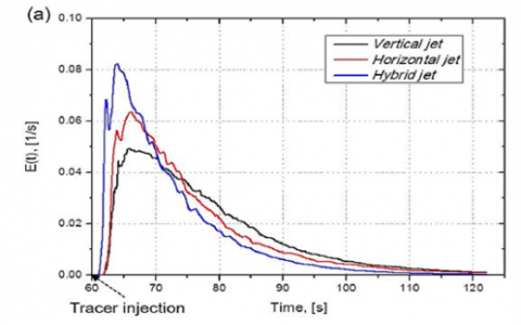
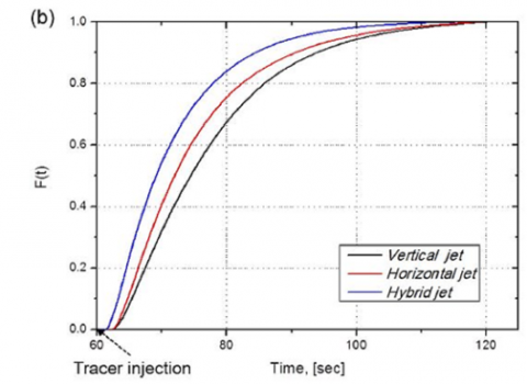
Figure 6. Solid residence time with different gas jet direction
During the gasification of coal in a circulating fluidized bed the solid residence time in riser section depends on different operating conditions. Some researchers studies on residence time for solid particles with positron emission particle tracking (PEPT) method inside the riser section by using Geldart B-type bed material. They have used different riser size such that 0.046, 0.09, 0.16 m ID with 4 m riser height [40]. Tracer technique is also a newly developed way to estimate the solid residence time distribution inside riser section. By using Eulerian-Eulerian model with kinetic theory of granular flow the particle motion and solid residence time can be calculated. Calculation of the residence time by CFD method is used for simulating experimental data to validate approach. Figure 6 (a, b) can explain solid residence time with different gas jet position. Figure 6 (a) shows that Vertical jet has a long residence time because there will be better mixing of gas-solid in case of vertical gas jet position. But in case of hybrid nozzle jet, it has less particle residence time because hybrid nozzle jet reduces the back mixing of solid particles so reduces the contact time for gas-solid phases. Figure 6 (b) shows the slower slopes, which denotes the recirculation of solid inside the riser section. Basically the solid back mixing follow this order vertical, horizontal, hybrid jet as shown in Figure 6 (a) & 6 (b) [41].
The mean and variance of residence time are summarised in Table 2.
Table 2. The variance of the residence time and mean residence time
|
S No. |
Verticle injection |
Horizontal injection |
Mixed injection |
|
Tm (s) |
16.25 |
14.75 |
11.45 |
|
σ2 |
137.57 |
121.42 |
86.61 |
$\frac{\Delta P}{L}=\mathcal{E}_{\mathrm{s} 1}\left(\rho_{p 1}-\rho_{\mathrm{g}}\right) \mathrm{g}+\mathcal{E}_{\mathrm{s} 2}\left(\rho_{p 2}-\rho_{\mathrm{g}}\right) \mathrm{g}$ (6)
2.3 Pressure drop inside riser
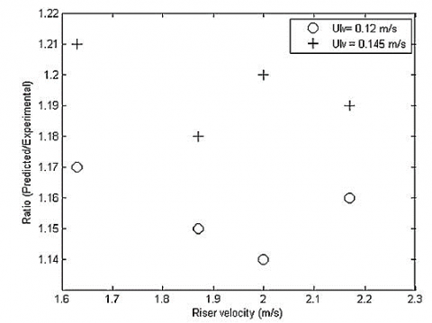
Pressure drop is a main factor in the design and development of CFB gasifiers. With some experimental results it was found that pressure drop in any CFB system is affected by riser air velocity and also velocity inside the L-valve. Some researchers [48] focused for explaining the results regarding pressure drop in riser section as shown in Figure 7.
Figure 7. Riser pressure drop for different riser velocity at Ulv= 0.12 m/s, and Ulv = 0.145 m/s
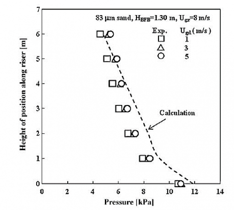
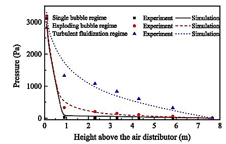
During the study it is found that when the riser velocity increases the pressure drop inside the riser section continuously decreases. Many previous articles reported that the pressure profile may be affected with different superficial gas velocity. If the inlet air velocity in the riser, continuously increases then the pressure profile could be decreases from top to bottom of the riser section. Pressure drop inside the riser decreases since the solid entrainment from riser increases with the increasing height of bed material. However in case of cyclone it is found that pressure inside the cyclone always increases with riser velocity. Pressure drop in loop-seal always depends on aeration velocity of loop-seal. Basically pressure drop inside the loop-seal always increases with the increase in the riser velocity, Ulv=0.12 m/s, and Ulv=0.145 m/s. The overall pressure drop in a circulating fluidized bed system is found out and explained about experimental performance to know about pressure drop with maximum solid mass flux with some experimental conditions [49]. Figure 8 shows the pressure distribution inside riser section with different experimental condition. To evaluate the pressure fluctuations inside the CFB system a cold test rig with cross sectional area 1.18 m2 and height 8.0 m was made to study the pressure distribution in circulating fluidized bed by using computational particle fluid dynamics. Pressure difference inside the combustion chamber may be measured by using different pressure transducer. Eulerian–Lagrangian model applied for this experiment to simulate the gas-solid behaviour in circulating fluidized bed system. There are some differences in simulation and experimental work. Different Pressure drop around the bed is found out near about 3000 Pa. The gas-solid flow is similar for both annular combustion chamber and conventional circulating fluidized bed riser due to these different pressure variations. A 3D Computational Particle Fluid Dynamic (CPFD) model is also a better technique for measurement of pressure drop in a circulating fluidized bed system. Some previous work [50] explained about this experimental work in a cold test unit. This model predicts the pressure along all working section of circulating fluidized bed system. During the experiment it has seen understood that pressure of the system continuously decreases from bottom to top of a circulating fluidized bed. All experimental and simulation work were performed for high feed rate. Some experiment [51] was performed in dual fluidized bed to predict the pressure drop inside the system. During the experiment they examined that pressure drop is generally affected by riser velocity. Pressure drop inside the circulating fluidized bed is also affected by system temperature.
Figure 8. Pressure distribution inside riser section
The pressure profile is shown in Figure 9 which reveals that the pressure fluctuates inside the combustion chamber with different flow regimes in bottom area.
Figure 9. Pressure profile inside the combustion chamber
Previous studies [52] confirmed that pressure drop inside the riser section continuously increases with linear ratio of solid flux to gas flux. This concept proves the momentum transfer concept for gas to particle at very high reaction temperature. When drag force is applied on the particle surface than the pressure inside the riser section decreases with decreasing the particle velocity or decreases with increase in the solid flux.
2.4 Solid-circulation rate
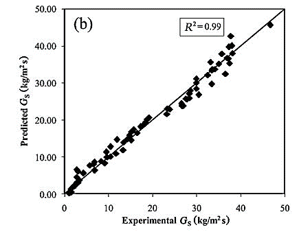
Solid circulation rate plays a vital role to estimate the hydrodynamic properties of CFB system. It is an important factor for the stable operation of CFB system. Some experiments [53] were performed with high solid circulation rate for analysing the energy balance. The circulation rate for solid particles in any circulating fluidized bed system can be measured by using energy and mass balance analysis. Many previous experimental works justified that for finding out the better solid circulation, large riser diameter will be more effective because riser geometry plays an important role on gasification as explain above. A high head gas blower to support the dense suspension is also required for obtaining better solid circulation rate. The parametric design to estimate the hydrodynamic analysis in solid-liquid circulating fluidized bed system was studied [54]. In this work the researchers have presented hydrodynamics as the average solid circulation rate and solid hold up. The predicted and experimental data as compared are shown in Figure 10.
Figure 10. Comparison of experimental and predicted solid circulation rate (Gs)
Figure 11. Gas velocity effect on solid circulation rate
The primary liquid velocity effect and solid inventory effect has a positive effect on solid circulation as demonstrated in Figure 10. When solids inventory and primary liquid velocity increases, solid circulation rate also increases. Hence in case of lower liquid velocity, solid circulation initially increases and then decreases with solid quantity in the downcomer. Particle velocity inside recycle chamber was examined in a CFB system [55]. The solid circulation rate can be controlled by loop in any CFB system. Inside the riser, velocity of gas also affects the solid circulation rate. Figure 11 depicts how the riser gas velocity affects the solid circulation.
During the experiment [56] in a horizontal CFB system, the particle distribution rate and solid circulation rate inside horizontal tube are explained. Particle distribution rate continuously decreases with increasing solid flow rate. Because the driving force of particle increases with increasing the solid circulating rate so that force is applied on particle on upward direction.
Previous studies on the solid circulation flux on internally circulating fluidized bed system where a single vessel was divided into two compartments with one as reaction chamber and another one as heat exchanger chamber. Behaviour of bed particle and solid circulation were studied by using kinetic theory of granular flow (KTGF) as explained above. The pressure difference between the chambers is the main factor that affects the solid flux. Previous experimental work also approached the way to explain the mechanism on solid transport in closed loop CFB system. In this experimental work solid circulation rate was measured by an external weighted hooper. With low gas velocity, the circulation rate continuously decreases. In this experimental work they have explained that solid circulation flow rate is a function of gas velocity [57]. For the study on ejector type solid circulation system in a CFB unit, solid circulation rate and gas flow rate at different cold flow conditions can be considered. It is seen in this experiment that the solid column height is controlled by motive gas flow rate. If the gas flow rate increases than flow rate decreases. In case of column without solid least amount of gas recirculates because of the common effect of ejector. During the experiment it was also observed that flow rate of solids was constant if the motive gas flow rate is more than a specific rate.
2.5 Coal feeder position and coal feeding rate
Coal feeding rate is an important factor to stabilise a Circulating fluidized bed system. With dense discrete phase model (DDPM) the particle transport and coal feeding rate in a circulating fluidized bed system can be investigated. It is a method to justify the coal feeding rate in the CFB system, which could be investigated through dense discrete phase model (DDPM). They have also utilized user defined function (UDFs) to extend the ANSYS FLUENT original code. It is found that there is no effect of change in the coal feeder position and feeding rate on pressure distribution, since the numerically calculated value for pressure and measured pressure values are approximately same. However in other hand it has also been observed that on bottom side, pressure gradient is higher but in top side of combustor it has lower value. Some previous studies [29] focus on the solid feeder effect and configuration of riser exit in high density circulating fluidized bed system. For this experimentation work on a circulating fluidized bed (0.05m ID×4.5 m H) were used with particle (bed material) properties, dp=70 μm, ρs=1740 kg/m3. The experimental work reveals that with increasing gas velocity the solid mass flux rate continuously increases. The maximum solid mass flux was obtained at 3-5 % range of primary and secondary gas velocity ratio. It was also found that circulating solid mass flux rate is higher on L-valve but in J-valve it is not very significant. The high solid circulation rate also depends on gas flow behaviour in the L-valve solid feeder and riser exit.
2.6 Temperature-effect
Gas particles heat transfer in CFB system takes place where the temperature difference between the gas and solid is very high. The bed heat transfer rates between the gas and solid particles again shows lower value because there is smaller difference between the gas and solid particles temperature [58]. Temperature and pressure basically affect the gasification process in CFB because it affects the gas density and gas viscosity. When the temperature of the system continuously increases during the gasification in CFBs units, density of gas also affected. Increasing the temperature of the system causes gas-viscosity to increase due to lower density because higher gas viscosity at higher temperature increases the drag on the particles, which decreases their inertial separation. Bed temperature also affects the produced gas composition and hence the quality. Temperature has an effect on the gas composition and carbon conversion in the gasification reaction. If the temperature of the CFB system increases continuously, which may cause the more carbon conversion, because higher temperature leads the more efficient gasification process. Some previous research [59] explained that during the gasification in CFB systems major parameters like gas yield, heating value and char/tar yield are affected by temperature. Some other research article explained about effect of temperature on gasification. The char yield decreases with gasification temperature [60-61]. Therefore, it is difficult to determine the effect on gas viscosity by changing system temperature as density of gas also changes with the changes of system temperature. Most of the gasification process takes place within the temperature range of (800-900 °C) where the gas viscosity increases over this temperature range. The minimum fluidization velocity (Umf) is also affected by the system temperature, because temperature decreases the density of particle (ρp). The Eq. (7) predicts that Umf should decrease with temperature for large particle but in case of small particle it should decrease with temperature.
$\mathrm{U}_{\mathrm{mf}}=\mathrm{d}^{2}\left(\rho_{\mathrm{p}}-\rho_{\mathrm{g}}\right) \mathrm{g}$ (7)
Rep, mf ˂ 20(small particle), where Rep, mf is the particle Reynolds number at minimum fluidization which is < 20.
The heat transfer rate between the gas and particles decreases with increasing solid concentration. In circulating fluidized bed system temperature of bed also play vital role during gasification. The efficiency of circulating fluidized bed gasifier also depends on the temperature of bed. It changes the pollutants (NOx, SOx, etc.) composition in the emission. Apart from the control of pollutants such as NOX and SO2 there are also other reasons to control the bed temperature. Other reason means during the gasification, bed temperature also affects the producer gas composition and bed temperature seems to improve the release of the gaseous phase during devolatilization. Therefore the temperature of bed should be in a certain range [62]. It is understood that pressure difference on riser section is also affected by temperature difference in circulating fluidized bed. With continuous temperature rising in riser section the pressure drop decreases. There are few studies on the effect of pressure drop due to temperature difference inside riser section in a CFB system [63-64]. For studies on the air/coal ratio and steam/coal ratio effect on reaction temperature earlier researchers used the da Xuzhou bituminous type coal in a CFB system and clarified that the increase in air/coal ratio increases the gasifier temperature but in case of steam/coal, bed temperature continuously decreases. The ratio also affects the CO and H2 concentration in the output gas [65-66].
Existing reported literatures were studied to carry out the hydrodynamic behaviour analysis for coal gasification in circulating fluidized bed. All parameters of hydrodynamic such as pressure, temperature, particle residence time, solid circulation rate etc. were considered to study the phenomena of coal gasification. It is observed that the gas-solid contact efficiency increases with the increase in superficial gas velocity. The gas-solid contact efficiency is also gets affected by particle size distribution. In other hand coal feeding rate and solid circulation rate affects the gasification in CFB systems. For better solid circulation rate larger riser diameter and small particle size is a necessary condition. Pressure drop inside the riser section fully depends on air velocity in riser and air velocity inside the L-valve. Obviously pressure drop inside the connecting valve increases which increases the velocity inside the riser.
The authors thankfully acknowledge the Director, National Institute of Technology Durgapur and the Director CSIR - Central Mechanical Engineering Research Institute (CSIR-CMERI), Durgapur for their continuous support and enthusiasm.
D Diameter of riser, m.
dp Diameter of particle, m.
Gs Solid circulation rate, kg/m2/s.
U Superficial air velocity in riser, m/s.
Umf Minimum fluidization velocity.
ρp Particle Density, kg/m3
ρ Density of gas/solid, kg/m3
εg Voidage.
εs Solid concentration.
v Velocity of solid/gas, m/s
Cpg Specific heat of gas, J/kg/K.
ρg Gas density, kg/m3.
A Cross sectional area of bed, m2.
Tg,1 Gas temperature on top of riser, °C.
Tg,2 Gas temperature of bed section, °C.
hgs Heat transfer coefficient between gas and solid, W/m2/k.
Tg Average gas temperature, K.
Tp Average temperature for solid, °C.
ΔZ Height of bed section, m.
Tr Mean solid residence time in riser, s.
Mr Solid inventory in riser, kg.
Ms Solid circulation rate, kg/s.
ρp Particle density, kg/m3.
Ԑr Average voidage in riser.
Ԑco Average voidage in the cross over.
Ars Cross-sectional area of riser, m2.
Aco Cross sectional area of the cross over, m2.
hrs Length of riser, m.
Up, co Mean solid velocity cross over, m/s.
ΔP Pressure difference, Pa.
L Tube length, m.
ρp1 Particle density of bed material (silica sand), kg/m3.
ρp 2 Particle density of bed material (nylonshot), kg/m3.
Ԑs1 Solid hold up of silica sand.
Ԑ s2 Solid hold up of nylonshot.
g Gravitational acceleration, m/s2.
Qg Average heat flux for gas only.
Qgs Average heat flux for gas and solid.
[1] Adeyemi, I., Janajreh, I. (2017). Gasification behaviour of coal and woody biomass: Validation and parametrical study. Applied Energy, 185: 1007-1018. https://doi.org/10.1016/j.apenergy.2016.05.119
[2] Basu, P. (2006). Combustion and gasification in fluidized bed. Taylor & Francis Group, Canada.
[3] Berruti, F., Chaouki, J., Wdfroy, L., Pugsley, T.S., Patience, G.S. (1995). Hydrodynamics of circulating fluidized bed risers: A review. The Canadian Journal of Chemical Engineering, 73: 579-602. https://doi.org/10.1002/cjce.5450730502
[4] Chalermsinsuwan, B., Chanchuey, T., Buakhao, W., Gidaspow, D., Piumsomboon, P. (2012). Computational fluid dynamics of circulating fluidized bed downer: Study of modelling parameters and system hydrodynamic characteristics. Chemical Engineering Journal, 189(190): 314-335. http://dx.doi.org/10.1016/j.cej.2012.02.020
[5] Chalermsinsuwan, B., Kuchonthara, P., Piumsomboon, P. (2010). CFD modeling of tapered circulating fluidized bed reactor risers: Hydrodynamic descriptions and chemical reaction responses. Chemical Engineering and Processing, 49: 1144-1160. https://doi.org/10.1016/j.cep.2010.08.016
[6] Chalermsinsuwan, B., Samruamphianskun, T., Piumsomboon, P. (2014). Effect of operating parameters inside circulating fluidized bed reactor riser with ring baffles using CFD simulation and experimental design analysis. Chemical Engineering Research and Design, 92: 2479-2492. https://doi.org/10.1016/j.cherd.2014.03.016
[7] Wang, C., Zhu, J., Li, C., Barghi, S. (2014). Detailed measurements of particle velocity and solids flux in a high density circulating fluidized bed riser. Chemical Engineering Science, 114: 9-20. https://doi.org/10.1016/j.ces.2014.04.004
[8] Dry, R.J., Christensen, I.N., White, C.C. (1987). Gas- solids contact efficiency in a high-velocity fluidised bed. Powder Technology, 52: 243-250. https://doi.org/10.1016/0032-5910(87)80111-0
[9] Farid, M.M., Jeong, H.J., Kim, K.H., Lee, J., Kim, D., Hwang, J. (2017). Numerical investigation of particle transport hydrodynamics and coal combustion in an industrial-scale circulating fluidized bed combustor: Effects of coal feeder positions and coal feeding rates. Fuel, 192: 187-200. https://doi.org/10.1016/j.fuel.2016.12.025
[10] Fushimi, C., Ishizuka, M., Guan, G., Suzuki, Y., Norinaga, K., Hayashi, J.I., Tsutsumi, A. (2014). Hydrodynamic behaviour of binary mixture of solids in a triple-bed combined circulating fluidized bed with high mass flux. Advanced Powder Technology, 25: 379-388. https://doi.org/10.1016/j.apt.2013.06.007
[11] Dwivedi, K.K., Shrivastav, P., Karmakar, M.K., Pramanick, A.K., Chatterjee, P.K. (2019). A comparative study on pyrolysis characteristics of bituminous coal and low-rank coal using thermogravimetric analysis (TGA). International Journal of Coal Preparation and Utilization, 39. https://doi.org/10.1080/19392699.2019.1566130
[12] Guana, G., Fushimia, C., Tsutsumi, A., Ishizuka, M., Matsuda, S., Hatano, H., Suzuki, Y. (2010). High- density circulating fluidized bed gasifier for advanced IGCC/IGFC—advantages and challenges. Particuology, 8: 602-606. https://doi.org/10.1016/j.partic.2010.07.013
[13] Gul, S., Ozdogan, Z.S. (2016). Ejector type solid circulation system analysis for circulating fluidized beds. International Journal of Multiphase Flow, 84: 116-128. https://doi.org/10.1016/j.ijmultiphaseflow.2016.04.020
[14] Gnanasundaram, N., Loganathan, M., Perumal, K. (2014). Solid holdup in liquid solid circulating fluidized bed with viscous liquid medium. Alexandria Engineering Journal, 53: 959-968. https://doi.org/10.1016/j.aej.2014.08.001
[15] Guo, Z., Wang, Q., Fang, M., Luo, Z., Cen, K. (2014). Thermodynamic and economic analysis of poly- generation system integrating atmospheric pressure coal pyrolysis technology with circulating fluidized bed power plant. Applied Energy, 113: 1301-1314. https://doi.org/10.1016/j.apenergy.2013.08.086
[16] Hassan, M., Schwarz, M.P., Yuqing, F., Rafique, M., Witt, P., Huilin, L. (2016). Numerical investigation of solid circulation flux in an internally circulating fluidized bed with different gas distributor design. Powder Technology, 301: 1103-1111. https://doi.org/10.1016/j.powtec.2016.07.011
[17] Harris, A.T., Davidson, J.F., Thorpe, R.B. (2003). Particle residence time distributions in circulating fluidized beds. Chemical Engineering Science, 58: 2181-2202. https://doi.org/10.1016/S0009-2509(03)00082-4
[18] Hong, K., Cao, M., Ullah, A. (2016). A bubble- based drag model at the local-grid level for eulerian simulation of bubbling fluidized beds. Mathematical Problems in Engineering, 2016: 1-11. http://dx.doi.org/10.1155/2016/8256816
[19] Issangya, A.S., Grace, J.R., Bai, D., Zhu, J. (2000). Further measurements of flow dynamics in a high- density circulating fluidized bed riser. Powder Technology, 111: 104-113. https://doi.org/10.1016/S0032-5910(00)00246-1
[20] Jiang, F., Bian, Y., Qi, G., Zhang, J., Wang, J., Feng, Q., Li, N., Han, X. (2016). Study on the particle distribution of a horizontal multi-tube circulating fluidized bed. Powder Technology, 295: 272-283. http://dx.doi.org/10.1016/j.powtec.2016.03.044
[21] Ju, F., Chen, H., Yang, H., Wang, H., Zhang, S., Liu, D. (2010). Experimental study of a commercial circulated fluidized bed coal gasifier. Fuel Processing Technology, 91: 818-822. https://doi.org/10.1016/j.fuproc.2009.07.013
[22] Dwivedi, K.K., Chatterjee, P.K., Karmakar, M.K., Pramanick, A.K. (2019). Pyrolysis characteristics and kinetics of Indian low rank coal using thermogravimetric analysis. International Journal of Coal Science and Technology, 6(1): 102-112. https://doi.org/10.1007/s40789-019-0236-7
[23] Kim, J.S., Tachino, R., Tsutsumi, A. (2008). Effects of solids feeder and riser exit configuration on establishing high density circulating fluidized beds. Powder Technology, 187: 37-45. https://doi.org/10.1016/j.powtec.2008.01.002
[24] Kim, Y.J., Lee, J.M., Kim, S.D. (2000). Modeling of coal gasification in an internally circulating fluidized bed reactor with draught tube. Fuel, 79: 69-77. https://doi.org/10.1016/S0016-2361(99)00128-3
[25] Li, C., Li, H., Zhu, Q. (2014). A hydrodynamic model of loop-seal for a circulating fluidized bed. Powder Technology, 252: 14-19. https://doi.org/10.1016/j.powtec.2013.10.029
[26] Li, T., Dietiker, J.F., Shadle, L. (2014). Comparison of full-loop and riser-only simulations for a pilot-scale circulating fluidized bed riser. Chemical Engineering Science, 120: 10-21. https://doi.org/10.1016/j.ces.2014.08.041
[27] Li, T., Gel, A., Pannala, S., Shahnam, M., Syamlal, M. (2014). CFD simulations of circulating fluidized bed risers part I: Grid study. Powder Technology, 265: 2-12. https://doi.org/10.1016/j.powtec.2014.01.021
[28] Li, P., Yu, X., Liu, F., Wang, T. (2015). Hydrodynamic behaviours of an internally circulating fluidized bed with wide-size-distribution particles for preparing polysilicon granules. Powder Technology, 281: 112-120. http://dx.doi.org/10.1016/j.powtec.2017.01.068
[29] Mahmoudi, S., Chan, C.W., Brems, A., Seville, J., Baeyens, J. (2012). Solids flow diagram of a CFB riser using Geldart B-type powders. Particuology, 10: 51-61. https://doi.org/10.1016/j.partic.2011.09.002
[30] Matsuoka, K., Hosokai, S., Kuramoto, K., Suzuki, Y. (2013). Enhancement of coal char gasification using a pyrolyzer–gasifier isolated circulating fluidized bed gasification system. Fuel Processing Technology, 109:43-48. http://dx.doi.org/10.1016/j.fuproc.2012.09.036
[31] Mo, X., Wang, P., Yang, H., Lv, L., Zhang, M., Liu, Q. (2015). A hydrodynamic model for circulating fluidized beds with low riser and tall riser’, Powder Technology, 274: 146-153. https://doi.org/10.1016/j.powtec.2015.01.022
[32] Nag, P.K., Ali, M.S. (1992). Effect of operating parameters on bed-to-wall heat transfer in a high temperature circulating fluidized bed. International Journal of Energy Research, 16: 61-73. https://doi.org/10.1002/er.4440160108
[33] Palkar, R.R., Shilapuram, V. (2015). Development of a model for the prediction of hydrodynamics of a liquid–solid circulating fluidized beds: A full factorial design approach. Powder Technology, 280: 103-112. https://doi.org/10.1016/j.powtec.2015.04.045
[34] Palkar, R.R., Shilapuram, V. (2017). Detailed parametric design methodology for hydrodynamics of liquid–solid circulating fluidized bed using design of experiments. Particuology, 31: 59-68. https://doi.org/10.1016/j.partic.2016.04.005
[35] Panday, R., Breault, R., Shadle, L.J. (2016). Dynamic modeling of the circulating fluidized bed riser. Powder Technology, 291: 522-535. https://doi.org/10.1016/j.powtec.2015.12.045
[36] Qiu, G., Ye, J., Wang, H. (2015). Investigation of gas– solids flow characteristics in a circulating fluidized bed with annular combustion chamber by pressure measurements and CPFD simulation. Chemical Engineering Science, 134: 433-447. https://doi.org/10.1016/j.ces.2015.05.036
[37] Qi, X., Song, G. (2016). Effects of wall temperature on slagging and ash deposition of Zhundong coal during circulating fluidized bed gasification. Applied Thermal Engineering, 106: 1127-1135. https://doi.org/10.1016/j.applthermaleng.2016.06.092
[38] Shrestha, S., Ali, B.S., Jan, B M., Lim, M., Sheikh, K E. (2016). Hydrodynamic properties of a cold model of dual fluidized bed gasifier: A modeling and experimental investigation. Chemical Engineering Research and Design, 109: 791-805. https://doi.org/10.1016/j.cherd.2016.04.002
[39] Shi, Z., Wang, W., Li, J. (2011). A bubble-based EMMS model for gas–solid bubbling fluidization. Chemical Engineering Science, 66: 5541-5555. https://doi.org/10.1016/j.ces.2011.07.020
[40] Simanjuntak, J.P., Zainal, Z.A. (2015). Experimental study and characterization of a two compartment cylindrical internally circulating fluidized bed gasifier. Biomass and Bioenergy, 77: 147-154. https://doi.org/10.1016/j.biombioe.2015.03.023
[41] Sundaresan, R., Kolar, A.K. (2013). Axial heat transfer correlations in a circulating fluidized bed riser. Applied Thermal Engineering, 50: 985-996. https://doi.org/10.1016/j.applthermaleng.2012.08.026
[42] Taba, L E., Irfan, M F., Daud, W A M. (2012). The effect of temperature on various parameters in coal, biomass and CO-gasification: A review. Renewable and Sustainable Energy Reviews, 16: 5584-5596. https://doi.org/10.1016/j.rser.2012.06.015
[43] Thapa, R.K., Frohner, A., Tondl, G., Pfeifer, C., Halvorsen, B.M. (2016). Circulating fluidized bed combustion reactor: Computational Particle Fluid Dynamic model validation and gas feed position optimization. Computers and Chemical Engineering, 9: 180-188. https://doi.org/10.1016/j.compchemeng.2016.05.008
[44] Wang, C., Zhu, J. (2016). Developments in the understanding of gas–solid contact efficiency in the circulating fluidized bed riser reactor: A review. Chinese Journal of Chemical Engineering, 24: 53-62. https://doi.org/10.1016/j.cjche.2015.07.004
[45] Wang, X., Wu, X., Lei, F., Lei, J., Xiao, Y. (2014). 3D full-loop simulation and experimental verification of gas–solid flow hydrodynamics in a dense circulating fluidized bed. Particuology, 16:218-226. https://doi.org/10.1016/j.partic.2013.11.010
[46] Won, Y.S., Jeong, A.R., Choi, J.H., Jo, S.H., Ryu, H.J., Yi, C.K. (2017). Temperature effects on riser pressure drop in a circulating fluidized bed. Korean Journal of Chemical Engineering, 34 (3): 913-920. https://doi.org/10.1007/s11814-016-0289-x
[47] Bi, X.T., Liu, X. (2010). High density and high solids flux CFB risers for steam gasification of solids fuels. Fuel Processing Technology, 91: 915-920. https://doi.org/10.1016/j.fuproc.2009.12.011
[48] Yoo, H., Moon, H., Choi, S., Park, Y.K., Cho, H.H. (2017). Effect of the jet direction of gas nozzle on the residence time distribution of solids in circulating fluidized bed risers. Journal of the Taiwan Institute of Chemical Engineers, 71: 235-243. https://doi.org/10.1016/j.jtice.2016.12.018
[49] Zhanga, H., Zhua, Z., Dong, Y.K., Lu, Q.G. (2015). Structural properties and gasification reactivity of shenmu fly ash obtained from a 5t/d circulating fluidized bed gasifier. Procedia Engineering, 102: 1104-1111. https://doi.org/10.1016/j.proeng.2015.01.233
[50] Zi, C., Sun, J., Yang, Y., Huang, Z., Liao, Z., Wang, J., Yang, Y., Han, G. (2017). CFD simulation and hydrodynamics characterization of solids oscillation behaviour in a circulating fluidized bed with sweeping bend return. Chemical Engineering Journal, 307: 604-620. https://doi.org/10.1016/j.cej.2016.08.127
[51] Singh, R.I., Mohapatra, S.K. (2011). Effect of bed temperature, fuel density and particle size on hydrodynamic parameters of 10 MW fluidized bed combustion power plant using riser waste. 10th International Conference on Circulating Fluidized Beds and Fluidization Technology CFB-10, T. Knowlton. http://dc.engconfintl.org/cfb10.
[52] Rago, Y.P., Surroop, D., Mohee, D. (2018). Torrefaction of textile waste for production of energy- dense biochar using mass loss as a synthetic indicator. Journal of Environmental Chemical Engineering, 6: 811-22. https://doi.org/10.1016/j.jece.2017.12.055
[53] Deng, Z., Xiao, R., Jin, B., Huang, H., Shen, L., Song, Q., Li, Q. (2008). Computational fluid dynamics modeling of coal gasification in a pressurized spout- fluid bed. Energy Fuels, 22: 1560-69. https://doi.org/10.1021/ef7007437
[54] Zhou, W., Zhao, C.S., Duan, L.B., Qu, C.R., Chen, X.P. (2011). Two-dimensional computational fluid dynamics simulation of coal combustion in a circulating fluidized bed combustor. Chemical Engineering Journal, 166: 306-14. https://doi.org/10.1016/j.cej.2010.09.048
[55] Prabhansu Karmakar, M.K., Chandra, P., Chatterjee, P.K. (2015). A review on the fuel gas cleaning technologies in gasification process. Journal of Environmental Chemical Engineering, 3(2): 689-702. https://doi.org/10.1016/j.jece.2015.02.011
[56] Dwivedi, K.K., Chatterjee, P.K., Karmakar, M.K., Pramanick, A.K. (2018). Experimental Study on pyrolysis of coal by thermogravimetric analysis (TGA) under different temperature conditions. Journal of Energy and Environmental Sustainability, 5: 49-52.
[57] Gokon, N., Izawa, T., Kodama, T. (2014) Steam gasification of coal cokes by internally circulating fluidized-bed reactor by concentrated Xe-light radiation for solar syngas production. Energy, 2014: 1-9. http://dx.doi.org/10.1016/j.energy.2014.11.012
[58] Farid, M.M., Jeong, H.J., Kim, K.H., Lee, J., Hwang, K.J. (2017). Numerical investigation of particle transport hydrodynamics and coal combustion in an industrial-scale circulating fluidized bed combustor: Effects of coal feeder positions and coal feeding rates. Fuel, 192: 187-200. https://doi.org/10.1016/j.fuel.2016.12.025
[59] Zou, C., Chen, Y., Kong, L., Sun, F., Chen, S., Dong, Z. (2019). Underground coal gasification and its strategic significance to the development of natural gas industry in China. Petroleum Exploration and Development, 46: 205-215. https://doi.org/10.1016/S1876-3804(19)60002-9
[60] Dwivedi, K.K., Prabhansu, Pramanick, A.K., Karmakar, M.K., Chatterjee, P.K. (2019). Indian sub-bituminous and low-rank coal gasification experiments in a circulating fluidized bed gasifier under air atmosphere. International Conference on Recent Innovations and developments in Mechanical Engineering (ICRIDME-2018), National Institute of Technology Meghalaya, Shillong, India.
[61] Prabhansu Ganguli, S., Dwivedi, K.K., Chandra, P., Karmakar, M.K., Chatterjee, P.K. (2019). Hydrodynamics of a CFB gasifier with two different cross sections in the riser. International Conference on Recent Innovations and Developments in Mechanical Engineering (ICRIDME-2018), National Institute of Technology Meghalaya, Shillong, India.
[62] Karmakar, M.K., Datta, A.B. (2010). Hydrodynamics of a dual fluidized bed gasifier. Advanced Powder Technology, 21: 521-28. https://doi.org/10.1016/j.apt.2010.02.001
[63] Upadhyay, M., Park, J.H. (2015). CFD simulation via conventional Two-Fluid Model of a circulating fluidized bed riser: Influence of models and model parameters on hydrodynamic behaviour. Powder Technology, 272: 260-68. https://doi.org/10.1016/j.powtec.2014.12.011
[64] Karmakar, M.K., Datta, A.B. (2011). Generation of hydrogen rich gas through fluidized bed gasification of biomass. Bioresource Technology, 102: 1907-13. https://doi.org/10.1016/j.biortech.2010.08.015
[65] Karmakar, M.K., Mandal, J., Haldar, S., Chatterjee, P.K. (2013). Investigation of fuel gas generation in a pilot scale fluidized bed autothermal gasifier using rice husk. Fuel, 111: 584-91. https://doi.org/10.1016/j.fuel.2013.03.045
[66] Kellartzis, I., Kokkinos, E., Stavropoulos, G., Zouboulis, A., Mitrakas, M. (2017). Techno-economic evaluation of tetravalent manganese feroxyhyte for Hg uptake from flue gases in a fixed-bed adsorption configuration. Journal of Environmental Chemical Engineering, 5(2): 2077-82. https://doi.org/10.1016/j.jece.2017.04.019