Rajesh Kumar* | Prabha Chand
© 2019 IIETA. This article is published by IIETA and is licensed under the CC BY 4.0 license (http://creativecommons.org/licenses/by/4.0/).
OPEN ACCESS
The present work proposes an analytical investigation on the energetic and exergetic performance of an air heating solar collector having absorber surface equipped with fins and twisted tapes of twist ratio Y=2,4,6 and 8. A mathematical model capable of predicting the energy and exergy efficiency has been developed. The effects of mass flow rate, twist ratio and insolation on the thermal and exergy efficiency have been studied. Further, a comparison has been made with the results of smooth absorber solar air heater to check the performance enhancement over it. The results indicated that the thermal efficiency increases monotonically with increase in air flow rate but the exergy efficiency curve first goes up, achieves its maxima and then declines. Decrease in twist ratio from Y=8 to 2 leads to improvement in the thermal efficiency for whole range of studied mass flow rate but enhancement in the exergy efficiency was observed only up to the mass flow rate of 0.022 kg/s thereafter it starts decreasing.
exergy efficiency, solar air heater, thermal efficiency, twisted tapes, twist ratio
Solar air heater is a unique kinds of heat exchanger that coverts the solar energy into heat energy to be used in room heating, fish drying, laundry and low temperature industrial applications etc. [1]. However, the conventional solar air heater suffers from poor heat conversion efficiency. Various passive elements e.g. extended surfaces [2, 3], corrugated absorber [4], artificial roughness [5, 6], packed bed [7], wire coils [8, 9], twisted tape [10] etc. have been utilized to ameliorate the performance of a solar air heater.
First law analysis or energy analysis is the conventional method of evaluating the performance of a thermodynamic system involving the transfer or conversion of energy. This usually involves performing the energy balance and evaluating the energy efficiency. However, it neither incorporate the effects of internal losses nor it shows the direction of the processes. It does also not quantify the usefulness or quality of energy associated with the process. Therefore, it may not only be the sufficient criteria to estimate the performance of a thermal system. Exergy is the maximum energy extracted when a system comes in equilibrium with the environment [11] and is measure of the quality of energy. Exergy analysis based on the second law of thermodynamics is a very useful tool to detect the irreversibilities, their relative magnitude and location within the system. Thus exergy analysis is more informative than energy analysis.
Sabzpooshani et al. [12] investigated the effect of fins and baffle parameters on the exergetic performance of finned and baffled solar air heater. It was observed that the effects of baffle width, distance between baffles and number of fins on exergy efficiency were more prominent at low flow rate, but at high flow rate, the trend was reversed. Ajam et al. [13] developed a correlation to predict the exergy efficiency of a solar air heater and used MATLAB toolbox to maximize the exergy efficiency. Manfrida [14] perceived that for low performance collectors smaller air temperature rise results in higher exergetic efficiency but for selectively coated, evacuated or focusing collectors it results in low exergy efficiency. Kar [15] verified that for maximum exergy yield of the flat plate solar collector at specific mass flow rate, there is an optimum inlet temperature. Suzuki [16] discussed the several phrases like exergy inflows, exergy leakage and exergy destruction concerned with the general theory of exergy balance and applied these to flat plate and evacuated solar collectors. Bahrehmand et al. [17] developed the mathematical model for the simulation of single and double glass cover solar air heater under forced convection. They compared the results of different solar air collector and found that at lower Reynolds number, among the collectors without fins, the collector having double glass cover and thin metal sheet is more efficient. Ucar and Inalli [18] tested a solar air heater with six different shape and arrangement of absorber surface with fins attached. They found an enhancement of 10-30 % in the thermal efficiency. Chabane [19] joined the longitudinal fins below the absorber plate and tested it for two air flow rate of 0.012 kg/s and 0.016 kg/s. They also compared its results with those of smooth absorber solar collector. It was found that integrating longitudinal fins inferior to the absorber plate results in a significant improvement in the thermal efficiency.
In recent decades, the use of twisted tape inserts in passage of fluid flow has become popular in many heat transfer applications. These twisted tape inserts produce swirl flow, offer effectively longer fluid flow with separating and blockage of flow cross section due to repeated change in surface geometry. This results in increased flow velocity and better fluid mixing. The net effect is the enhanced heat transfer coefficients and hence the heat transfer rate. A detailed review to enhance the heat transfer rate has been presented by Web and Kim [20]. Jaisankar et al. [21] in his experiment investigated the heat transfer and friction factor of the helical twisted tape inserted solar water heater. They revealed that for similar operating conditions the heat transfer and pressure drop were significant in the twisted tape collector than that of the plain tube collector. Furthermore, they found that the twisted tape with minimum twist ratio yielded the high useful heat gain in comparison to higher twist ratios. Hassan and Sumathy [22] carried out an experiment for the range of Reynolds number 8.05 x 10³ to 1.36 x 10⁴ under constant heat flux to investigate the performance of solar collector by placing the twisted tapes of two twist ratios 23 and 11 in the tubes. They reported that in comparison to plain tube solar collector the collector with twisted tapes could enhance the heat transfer by 1.15 to 1.7 times.
So far the use of twisted tape is used in augmentation of heat transfer in the heat exchanger of fluid flow through tubes. No systematic efforts have been made to utilize the twisted tape in the duct of flat plate solar air collectors. Although in concentrated tube, the use of twisted tape has been seen in the literature. In the present paper a mathematical formulation has been generated to predict the thermal and exergetic performance of air heating collector with absorber plate equipped with fins and twisted tapes. The parameters; twist ratio, air flow rate and solar radiation intensity (insolation) is varied to analyze their effects on thermal and exergetic performance.
The quantitative and qualitative performance of the solar air collector can be evaluated by writing the energy and exergy balance during the heat exchange process.
2.1 Energy analysis
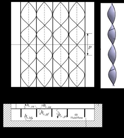
Figure 1. shows the schematic diagram of air heating solar collector having absorber plate equipped with fins and twisted tape inserts. For the analysis, energy balance equations of the different elements of the heater have been formulated with the following suppositions [1].
The temperature of air varies only in the direction of fluid flow.
Figure 1. Schematic diagram of solar air heater with fins and twisted tape inserts
Under aforesaid assumptions, the steady state energy balance equations for the glass cover, absorber plate, bottom plate and air scripted as:
Glass cover:
$α_g I+(h_{r,pg}+h_{c,pg} )(T_p-T_g )=(h_w+h_{r,ga})(T_g-T_a)$ (1)
Absorber plate:
$Iα_p τ_g=(h_{r,pg}+h_{c,pg} )(T_p-T_g )+h_{r,pb} (T_p-T_g )+h_{c,Rf} (T_p-T_f )+(NA_3/A_p)(T_p-T_g)$ (2)
Bottom plate:
$h_{r,pb}(T_p-T_b )+h_{c,fb}(T_f-T_b )=U_b (T_b-T_a)$ (3)
Air:
$h_{c,Rf} (T_p-T_b )+((NA_3)/A_p )(T_p-T_f )=2((mc_p)/A_p )(T_f-T_i )+h_{c,fb} (T_f-T_b )$ (4)
where, $A_3=\frac{mk_{fn}A_{fn}[sinhA_1+A_2coshA_1]}{coshA_1+A_2 sinhA_1}$ in which $A_1=mH_f$ and $A_2=h_{c,pf}/mk_{fn}$
Eqns. (1)- (4) can be arranged in a 4x4 matrix form as [A] [T] = [C]
$\left[ \begin{matrix} {{a}_{11}} & {{a}_{12}} & 0 & 0 \\{{a}_{21}} & {{a}_{22}} & {{a}_{23}} & {{a}_{24}} \\ 0 & {{a}_{32}} & {{a}_{33}} & {{a}_{34}} \\ 0 & {{a}_{42}} & {{a}_{43}} & {{a}_{44}} \\\end{matrix} \right]\left[ \begin{matrix} {{T}_{g}} \\ {{T}_{p}} \\ {{T}_{b}} \\ {{T}_{f}} \\\end{matrix} \right]=\left[ \begin{matrix} {{C}_{1}} \\ {{C}_{2}} \\ {{C}_{3}} \\ {{C}_{4}} \\\end{matrix} \right]$ (5)
where
$a_{11}=h_w+h_{r,ga}+h_{r,pg}+h_{c,pg}a_{12}=-(h_{r,pg}+h_{c,pg})$,
$a_{21}=(h_{r,pg}+h_{c,pg})$,
$a_{22}=h_{r,pg}+h_{c,pg}+h_{r,pb}+h_{c,pf}, a_{23}=h_{r,pb}=a_{32}$,
$a_{24}=h_{r,pf}+NA_3/A_p=-a_{42}, a_{34}=h_{c,fb}=a_{43}$,
$a_33=-(NA_3/A_p+2mc_p/A_p+h_{c,fb})$ and
${{C}_{1}}=I{{\alpha }_{g}}+({{h}_{w}}+{{h}_{r,ga}}){{T}_{a}},{{C}_{2}}=I{{\tau }_{g}}{{\alpha }_{p}},{{C}_{3}}=-{{U}_{b}}{{T}_{a}},{{C}_{4}}=2m{{c}_{p}}/{{A}_{p}}$
The above matrix can be solved for the unknown temperatures $T_g, T_p, T_b$ and $T_f$$ as:
[T]=[A]-1[C] (6)
For the solution of the above equations, the values of the various convective and radiative heat transfer coefficients associated with the different elements of matrix can be evaluated as [23] :
hw=2.8+3.0Cw (7)
${{h}_{r,ga}}=\sigma {{\varepsilon }_{g}}(T_{g}^{4}-T_{s}^{4})/({{T}_{g}}-{{T}_{a}})$ (8)
where $T_s$ is temperature of the sky estimated as ${{T}_{s}}=0.0552T_{a}^{1.5}$ [23]
${{h}_{r,pg}}=\frac{\sigma (T_{p}^{2}+T_{g}^{2})({{T}_{p}}+{{T}_{g}})}{1/{{\varepsilon }_{p}}+1/{{\varepsilon }_{p}}-1}$ (9)
${{h}_{r,pg}}=\frac{\sigma (T_{p}^{2}+T_{b}^{2})({{T}_{p}}+{{T}_{b}})}{1/{{\varepsilon }_{p}}+1/{{\varepsilon }_{p}}-1}$ (10)
The natural convective heat transfer coefficient of air in between the glass cover and absorber plate can be numerated as:
$h_{c,pg}=Nu_{pg}/L$ (11)
Nusselt number between absorber plate and glass cover ($Nu_{pg}$ ) is expressed as [1]
$N{{u}_{pg}}=1+1.44\left[ 1-{{\frac{1708(\sin 1.8\beta )}{Ra\cos \beta }}^{1.6}} \right]{{\left[ 1-\frac{1708}{Ra\cos \beta } \right]}^{+}}\left[ {{\left( \frac{Ra\cos \beta }{5803} \right)}^{1/3}}-1 \right]$ (12)
where, Ra is the Rayleigh number and $β$ is tilt angle of the collector and + sign denotes that only positive value of terms in the square bracket should be used.
The convective heat transfer coefficient of air in the flow duct can be estimated as:
h c,pf=h c,bf =Nu pbk air /Dh (13)
where, $Nu_{pb}$ is the Nusselt number of air between absorber plate and bottom plate and $D_h$ is hydraulic diameter of the duct.
For the air flow in smooth duct, the Nusselt number for the laminar and turbulent flow can be computed from the relationship reported by Heaton et al. [24] and Kay’s data respectively.
$N{{u}_{pb}}=\left\{ \begin{matrix} 4.4+\frac{0.00398{{(0.7\operatorname{Re}{{D}_{n}}/{{L}_{1}})}^{1.66}}}{1+0.00114{{(0.7\operatorname{Re}{{D}_{h}}/{{L}_{1}})}^{1.12}}}la\min ar\text{ flow} \\ 0.00158{{\operatorname{Re}}^{0.8}}\text{ turbulent flow} \\\end{matrix} \right.$ (14)
In case of flow of air in duct with twisted tapes, the correlations suggested by Hong and Bergles [25] and Bas and Ozceyhan [26] can be used to predict the Nusselt number for laminar and turbulent flow respectively.
$N{{u}_{pb}}=\left\{ \begin{matrix} 5.172{{[1+5.484*{{10}^{-3}}{{\Pr }^{0.7}}{{(\operatorname{Re}/Y)}^{1.25}}]}^{0.5}}\text{ laminar flow} \\ 0.6{{\operatorname{Re}}^{0.57}}{{Y}^{-0.45}}{{\Pr }^{0.4}}\text{ turbulent flow} \\\end{matrix} \right.$ (15)
The hydraulic diameter, $D_h$can be defined as:
${{D}_{h}}=\left\{ \begin{matrix} 2H{{L}_{2}}/(H+{{L}_{2}})\text{ ,plane duct} \\ 2(H{{F}_{p}}-{{t}_{f}}H{}_{f})/({{F}_{P}}+{{H}_{f}})\text{,duct with fins and twisted tapes} \\\end{matrix} \right.$ (16)
The pressure loss across the duct can be estimated by the equation
$\Delta p=\frac{4f\rho {{L}_{1}}{{V}^{2}}}{2{{D}_{h}}}$ (17)
where, f is the fanning friction factor computed as:
For flow in the smooth duct [23]
equ- (18)
In case of flow in the duct with twisted tapes
For Laminar flow: [27]
$\begin{align}&f=38.4{{(\operatorname{Re}/Y)}^{-0.95}},(\operatorname{Re}/Y<100) \\ & =(8.8201+2.1193Y-0.2108{{Y}^{2}}-.0069{{Y}^{3}}){{(\operatorname{Re}/\text{Y})}^{\text{-0}\text{.7}}},(\operatorname{Re}/Y>100) \\ \end{align}$ (19)
Turbulent flow: [26]
f=12.32Re-0.45Y-0.65 (20)
2.2 Exergy analysis
During the exergy analysis following assumptions has been considered [28]:
(a) Steady state operation
(b) Negligible kinetic and potential energy
(c) Specific heat of air is constant
The exergy balance equation for steady flow considering the solar air collector as the control volume is
Exi-Ex0-Exd=0 (21)
The exergy associated with fluid at temperature 'T' and pressure'P' is expressed as [13]:
Ex=mcp[(T-Ta)-TaIn(T/Ta)]+mRTaIn(P/Pa) (22)
where, 'Pa' is ambient pressure and 'R' is the characteristic constant of air.
The inlet exergy rate 'Exi' includes the exergy rate associated with inlet fluid flow and radiated exergy rate from the sun.
Exi=Exi,f+Exr (23)
Using Eq. (22) the exergy rate associated with inlet fluid flow can be written as follows:
Exi,f =mcp[(Ti-Ta)-TaIn(Ti/Ta)]+mRTaIn(Pi/Pa) (24)
The solar radiated exergy rate can be given by the equation
Exr=(1-Ta/Ts)IAc (25)
The outlet exergy rate'Ex0 'comprises of the exergy rate of outlet fluid flow and the rate of exergy leakage due to heat leakage from the air heater to ambient air.
Ex0=Ex0,f+Ex1 (26)
Ex0,f =mcp[(T0-Ta)-TaIn(T0/Ta)]+mRTaIn(P0/Pa) (27)
Ex1=ULAp(Tp-Ta)(1-Ta/Tp) (28)
where, UL is total loss coefficient and can be estimated by the following expression:
UL=Ub+Ut (29)
In which, Ut is the top loss coefficient, expressed as:
${{U}_{t}}={{\left(\frac{1}{{{h}_{r,pg}}+{{h}_{c,pg}}}+\frac{1}{{{h}_{r,ga}}+{{h}_{w}}}\right)}^{-1}}$ (30)
Substituting the Eqs. (27)-(32), into Eq. (25) the derived equation is
(1-Ta/Ts)IAc-mCp(T0-Ti)+mcpTaIn(T0/Ti)-mRTaIn(P0/Pi)-ULAp(Tp-Ta)(1-Ta/Tp)=Exd (31)
The difference of exergy associated with air leaving and entering the duct is termed as increase in flow exergy or exergy recovered.
Exrec=Exo,f-Exi,f=mcp(T0-T1)-mcpTaIn(T0/T1)+mRTaIn(P0/P1) (32)
The second law (or exergy) efficiency of a flat plate solar air collector is given by the expression [11]:
$_{{{\eta }_{2}}=\frac{\text{Exergy recovered}}{\text{Exergy supplied}}=\frac{m{{c}_{p}}({{T}_{0}}-{{T}_{i}})-m{{c}_{p}}{{T}_{a}}In({{T}_{0}}/{{T}_{i}})+mR{{T}_{a}}In({{P}_{0}}/{{P}_{i}})}{(1-{{T}_{a}}/{{T}_{s}})I{{A}_{c}}}}$ (33)
where Ts is the apparent temperature of sun which can be taken as 4330 K [29].
To predict the performance of the purposed system, a numerical simulation code has been generated. For the numerical calculation, the design and operational parameters as listed in Table 1 have been taken into account.
Table 1. Design and operating parameters used in the analysis
|
L1=1.2 m |
tf= 0.001 m |
m=0.001-0.06 kg/s |
|
L2= 0.4 m |
θ=00 |
Kins=0.05 W/mK |
|
H = 0.03 m |
Vw =2.5 m/s, |
Kfn=50 W/mK |
|
L = 0.04 m |
I=900 W/m2 |
Y=2,4,6,8 |
|
Hf= 0.03 m |
Ta=300K |
Ti=303K |
|
tins= 0.006 m |
Fp=3 cm |
${{\alpha }_{g}}$=0.11 |
|
${{\alpha }_{p}}$=0.96 |
${{\varepsilon }_{g}}$=0.9 |
${{\tau }_{g}}$=0.88 |
|
${{\varepsilon }_{p}}$=0.95 |
${{\varepsilon }_{b}}$=0.95 |
|
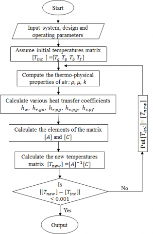
Figure 2. Procedure of the numerical simulation
The following steps are adopted for the numerical solution of the model:
The algorithms involved in the calculation procedure is shown in Figure 2.
The present theoretical model has been validated by comparing the thermal efficiency ( $η_{th}$ ) and exergy efficiency ( $η_2$) of the smooth absorber solar air heater with the results of Gupta and Kaushik [30] under the same design and operating conditions. The comparative results plotted for Re has been presented in Figure 3. From this Figure ure it can be seen that the present data are in good agreement with Gupta and Kaushik [30].
Figure 3. Verification of thermal and exergy efficiency of smooth absorber solar air heater of present study with the results of Gupta and Kaushik [30]
The current section presents the results of numerical simulation of the proposed system. Effects of parameters: twist ratio, mass flow rate and insolation on the thermal and exergy efficiency have been plotted and discussed.
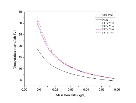
Figure 4 shows the plot of temperature rise of air against the mass flow rate for the plane collectors and the collectors fitted with fins and twisted tape inserts for various twist ratios at fixed value of solar incident radiation. From the plot, the temperature rise is seen to increase with decrease in mass flow rate. For a given mass flow rate the temperature rise of the collector having absorber fitted with fins and twisted taps of twist ratio Y=2, shows the highest temperature rise. This is attributed to the enhanced heat transfer area exposed to the air due to addition of fins and improved heat transfer coefficients because of insertion of twisted tapes. At a given mass flow rate of 0.013 kg/s, the temperature rise of air for the plane absorber solar air heater increases from 13.2◦C to 21.44˚C when the absorber plate is equipped with fins and twisted tape of twist ratio, Y=2.
Figure 4. Variation of temperature rise of air against the mass flow rate for different twist ratios
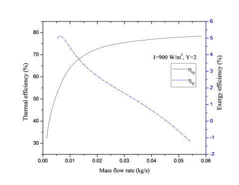
Variation of thermal efficiency ($η_{th}$) and exergy efficiency ($η_2$) of the collector with absorber plate attached with fins and twisted tapes against the air flow rate for twist ratio Y=2, and insolation I=900 W/m2 is plotted in Figure 5 to show the difference in these efficiencies. The Figure ure indicates that the thermal efficiency curve follows the monotonically increasing trend with increasing in mass flow rate. This is because the heat transfer coefficient of air in the duct is increased due to increased velocity at higher mass flow rate. However, exergy efficiency first goes up, achieves its maxima and then declines. This is attributed to high exergy loss from the absorber plate at higher mass flow rate.
Figure 5. Variation of thermal and exergy efficiency with mass flow rate for solar air heater with fins and twisted tape insert
Figure 6 depicts the effects of twist ratio and mass flow rate on the thermal efficiency ( $η_1$) for insolation I=990 W/m2. It is observed from the Figure ure that, for all twist ratio, increasing mass flow rate leads to increase in thermal efficiency. For any twist ratio, the thermal efficiency of the heater with fins and twisted tape is higher than those of smooth absorber solar air heater. This is because, addition of fins and twisted tapes in the flow path of air increase the heat transfer area as well as offer effectively longer flow length and introduce swirl flow resulting in improved fluid mixing thereby increasing the rate of heat transfer. The thermal efficiency of the collector with the minimum twist ratio is found to be highest among all twist ratios. This happens for the reason that the twisted tape with minimum twist ratio produces high intensity swirl flow and offer larger hydraulic length.
Figure 6.Variation of mass the thermal efficiency with mass flow rate for different twist ratios
Figure 7. Variation of exergy efficiency against the mass flow rate and twist ratio
The effect of insolation on the temperature rise of air for the collector with plane absorber and absorber with fins and twisted tapes at a mass flow rate of 0.001 kg/s is plotted in Figure 8. Figure ure indicates that for all collectors, the temperature rise of air increases linearly with advancement of mass flow rate. Also, for a given value of the insolation, the temperature rise of air is seen to increase with decrease in twist ratio. The rate of increment in the temperature rise is increasing with fall in twist ratio i.e. the slope of the line of temperature rise is increasing at lower twist ratio.
The response of twisted tape parameter on the thermal efficiency against the solar insolation is graphed in Figure 9. It is seen that the thermal efficiency increase with advancement of the solar radiation intensity and reducing twist ratio. At solar intensity of 900 W/m2, the addition of fins and twisted tape of twist ratio Y=2, enhances the thermal efficiency of the plane solar air collector from 56.1% to 74.42%.
Figure 8.Variation of temperature rise of air with respect to incident solar radiation
Figure 9. Variation of Thermal efficiency with solar radiation intensity
Figure 10. Variation of the exergy efficiency against the solar intensity and twist ratio
The effect of insolation ‘I ' on the exergy efficiency for various twist ratios at air flow rate of 0.011 kg/s is sketched in Figure 10. It is seen that, increase in insolation and decrease in twist ratio leads to increase in exergy efficiency As radiation intensity increases, outlet temperature of air and hence exergy recovered increases but at the same time solar radiated exergy rate also increases and hence the exergy supplied. However, the rate of increase of exergy recovered is more than the rate of exergy supplied resulting in an increased exergy efficiency. The exergy efficiency for twist ratio ‘Y=2’ increases from 1.7 % to 3.8 % as insolation increases from 400 W/m2 to 1000 W/m2.
The current paper, the effect of parameters; mass flow rate, twist ratio and insolation on the thermal and exergy efficiency of finned and twisted tape absorber solar air heater has been studied analytically. Following inferences can be drawn from the study.
|
Ac , Ap |
area of collector and absorber plate respectively (m2) |
|
C |
conversion factor |
|
cp |
specific heat of air (J/kg-K) |
|
Dh |
hydraulic diameter (m) |
|
Exi,f |
exergy at inlet of fluid |
|
Ex0,f |
exergy at outlet of fluid |
|
Exr,f |
exergy radiated from the sun (W) |
|
Fp |
fin pitch (distance between two fins, m) |
|
f |
fanning friction factor |
|
H |
duct height (m) |
|
Hf |
fins height (m) |
|
hw |
heat transfer coefficient due to wind flowing over the glass cover (W/m2K) |
|
hr,ga , hr,pg , hr,pb |
radiative heat transfer coefficient between glass cover and ambient, absorber plate and glass cover, and absorber plate and bottom plate respectivelly (W/m2K) |
|
hc,pg , hc,pf , hc,fb |
convective heat transfer coefficient between absorber plate and glass cover, absorber plate and air stream, air stram and bottom plate respectively (W/m2K) |
|
I |
radiation intensity (W/m2) |
|
kair , kins , kfn |
thermal conductivity of air , insulation and fins respectively (W/mK) |
|
L |
distance between glass cover and absorber plate (m) |
|
L1 |
length of the collector (m) |
|
L2 |
width of the collector (m) |
|
$\dot{m}$ |
mass flow rate of air (kg/s) |
|
N |
number of fins |
|
Nupg |
Nusselt number between absorber plate and glass cover. |
|
Nupb |
Nusselt number between absorber plate and bottom plate. |
|
p |
pitch for 180˚ rotation of twisted tape (m) |
|
Qu |
useful heat gain (W) |
|
Re |
Reynolds number |
|
Ti , T0 |
inlet and outlet temperature of air (K) |
|
Ta |
ambient temperature (K) |
|
Tg , Tp , Tb , Tf |
average temperature of glass cover, absorber plate, bottom plate and fluid respectively (K) |
|
tf , tins |
thickness of fins and insulation respectively (m) |
|
Ub |
bottom heat loss coefficient (W/m2K) |
|
Vw |
wind velocity (m/s) |
|
w |
width of twisted tape which equals to fin pitch |
|
Y |
twist ratio = p/w, dimensionless |
|
αp , αg |
absorptivity of absorber plate and glass cover respectively |
|
εp , εb , εg |
emissivity of absorber plate, bottom plate and glass cover respectively |
|
σ |
Stefan’s constant (5.67x10⁻⁸ Wm-2K-4) |
|
△p |
pressure drop (N/m2) |
|
ρ |
density of air (kg/m3) |
|
ηf |
fins efficiency |
|
ηth , ηeff , ηII |
Thermal, effective or thermohydraulic and exergy efficiency respectively |
[1] Duffie JA, Beckman WA. (2013). Solar engineering of thermal processes: Fourth edition. Fourth. John Wiley & Sons. https://doi.org/10.1002/9781118671603
[2] Kumar R, Chand P. (2017). Performance enhancement of solar air heater using herringbone corrugated fins. Energy 127: 271–9. https://doi.org/10.1016/j.energy.2017.03.128
[3] Rai S, Chand P, Sharma SP. (2016). Investigation of an offset finned solar air heater based on energy and exergy performance. Iran J Energy Environ 7: 212–20.
[4] El-Sebaii AA, Aboul-Enein S, Ramadan MRI, Shalaby SM, Moharram BM. (2011). Investigation of thermal performance of-double pass-flat and v-corrugated plate solar air heaters. Energy 36: 1076–86. https://doi.org/10.1016/j.energy.2010.11.042
[5] Kumar S, Saini RP. (2009). CFD based performance analysis of a solar air heater duct provided with artificial roughness. Renew Energy 34: 1285–91. https://doi.org/10.1016/j.renene.2008.09.015
[6] Saini RP, Verma J. (2008). Heat transfer and friction factor correlations for a duct having dimple-shape artificial roughness for solar air heaters. Energy 33: 1277–87. https://doi.org/10.1016/j.energy.2008.02.017
[7] Chouksey VK, Sharma SP. (2016). Investigations on thermal performance characteristics of wire screen packed bed solar air heater. Sol Energy 132: 591–605. https://doi.org/10.1016/j.solener.2016.03.040
[8] Chang SW, Gao JY, Shih HL. (2015). Thermal performances of turbulent tubular flows enhanced by ribbed and grooved wire coils. Int J Heat Mass Transf 90: 1109–24. https://doi.org/10.1016/j.ijheatmasstransfer.2015.07.070
[9] Garcia A, Solano JP, Vicente PG, Viedma A. (2007). Enhancement of laminar and transitional flow heat transfer in tubes by means of wire coil inserts. Int J Heat Mass Transf 50: 3176–89. https://doi.org/10.1016/j.ijheatmasstransfer.2007.01.015
[10] Nanan K, Yongsiri K, Wongcharee K, Thianpong C, Eiamsa-ard S. (2013). Heat transfer enhancement by helically twisted tapes inducing co- and counter-swirl flows. Int Commun Heat Mass Transf 46: 67–73. https://doi.org/10.1016/j.icheatmasstransfer.2013.05.015
[11] Cengel YA, Boles MA. (2011). Thermodyamics an engineering approach. 7th editio. New Delhi: Tata McGraw-Hill. https://doi.org/10.1017/CBO9781107415324.004
[12] Sabzpooshani M, Mohammadi K, Khorasanizadeh H. (2014). Exergetic performance evaluation of a single pass baffled solar air heater. Energy 64: 697–706. https://doi.org/10.1016/j.energy.2013.11.046
[13] Ajam H, Farahat S, Sarhaddi F. (2005). Exergetic optimization of solar air heaters and comparison with energy analysis. Int J Thermodyn 8: 183–90.
[14] Manfrida G. (1985). The choice of an optimal working point for solar collectors. Sol Energy 34: 513–5. https://doi.org/10.1016/0038-092X(85)90025-8
[15] Kar AK. (1985). Exergy efficiency and optimum operation of solar collectors. Appl Energy 21: 301–14. https://doi.org/10.1016/0306-2619(85)90014-5
[16] Suzuki A. (1988). General theory of exergy-balance analysis and application to solar collector. Energy 13: 153–160.
[17] Bahrehmand D, Ameri M, Gholampour M. (2015). Energy and exergy analysis of different solar air collector systems with forced convection. Renew Energy 83: 1119–30. https://doi.org/10.1016/j.renene.2015.03.009
[18] Ucar A, Inalli M. (2006). Thermal and exergy analysis of solar air collectors with passive augmentation techniques. Int Commun Heat Mass Transf 33: 1281–90. https://doi.org/10.1016/j.icheatmasstransfer.2006.08.006
[19] Chabane F, Moummi N, Benramache S. (2014). Experimental study of heat transfer and thermal performance with longitudinal fins of solar air heater. J Adv Res 5: 183–92. https://doi.org/10.1016/j.jare.2013.03.001.
[20] Webb RL, Kim NH. (2005). Principles of Enhanced Heat Transfer. Second Edi. New York: Taylor & Francis.
[21] Jaisankar S, Radhakrishnan TK, Sheeba KN. (2009). Experimental studies on heat transfer and friction factor characteristics of forced circulation solar water heater system fitted with helical twisted tapes. Sol Energy 83: 1943–52. https://doi.org/10.1016/j.solener.2009.07.006
[22] Hasan MA, Sumathy K. (2009). Study on the potential use of helical swirl generators in enhancing the thermal performance of solar air heaters. Int J Ambient Energy 30: 207–16. https://doi.org/10.1080/01430750.2009.9675098
[23] Watmuff JH, Charters WWS, Proctor D. (1977). Solar and wind induced external coefficients - Solar collectors. Coop Mediterr Pour l’Energie Solaire, Rev Int d’Heliotechnique, 2nd Quarter, 56.
[24] Heaton HS, Reynolds WC, Kays WM. (1964). Heat transfer in annular passages. Simultaneous development of velocity and temperature fields in laminar flow. Int J Heat Mass Transf 7: 763–81. https://doi.org/http://dx.doi.org/10.1016/0017-9310(64)90006-7
[25] Hong SW, Bergles A. (1976). Augmentation of laminar flow heat transfer in tubes by leans of twisted-tape inserts. J Heat Transfer 98: 251–6.
[26] Bas H, Ozceyhan V. (2012). Heat transfer enhancement in a tube with twisted tape inserts placed separately from the tube wall. Exp Therm Fluid Sci 41: 51–8. https://doi.org/10.1016/j.expthermflusci.2012.03.008
[27] Date AW, Saha SK. (1990). Numerical prediction of laminar flow and heat transfer characteristics in a tube fitted with regularly spaced twisted-tape elements. Int J Heat Fluid Flow 11: 346–54. https://doi.org/10.1016/0142-727X(90)90058-J
[28] Esen H. (2008). Experimental energy and exergy analysis of a double-flow solar air heater having different obstacles on absorber plates. Build Environ 43: 1046–54. https://doi.org/10.1016/j.buildenv.2007.02.016
[29] Kalogirou SA, Karellas S, Braimakis K, Stanciu C, Badescu V. (2016). Exergy analysis of solar thermal collectors and processes. Prog Energy Combust Sci 56: 106–37. https://doi.org/10.1016/j.pecs.2016.05.002
[30] Gupta MK, Kaushik SC. (2009). Performance evaluation of solar air heater for various artificial roughness geometries based on energy, effective and exergy efficiencies. Renew Energy 34: 465–76. https://doi.org/10.1016/j.renene.2008.06.001