OPEN ACCESS
Glass production is an energy-intensive and a high-polluting industry. This study has the aim to describe the computational approaches developed and set up for the analysis of the innovative Strategic Waste Gas Recirculation (WGR) System applied to the glass industry to new or existing furnaces. The final goal is to reduce the production of NOx during combustion making a primary combustion zone poor of oxygen. In order to have a controlled combustion in the primary zone it is of utmost importance to properly design the recirculation system to get the desired distribution of the recirculated gases in a specific zone over the methane injection. Moreover, the WGR system can have a second positive effect: it enhances the thermal performance of the regeneration system due to the radiating capacity of the exhaust flow recirculated that contains CO2 and H2O molecules. A CFD approach is presented and its applications to the design and optimization of WGR system are discussed. A numerical model for the evaluation of the emissive properties of radiant gases is developed and used for a parametric analysis on the thermal effects introduced by the WGR system.
glass furnace, exhaust gas recovery system, gas emissivity
The glass production sector is a high-energy consuming industry the melting process requires high temperatures consequently almost the totality of the plants operate by burning fossil fuels, as natural gas. On the other hand, the demand for glass, especially in the food industry, is growing due to the glass chemical characteristics and recyclability.
This industry sector is therefore high environmentally impactful from the greenhouse gases viewpoint. For this reason the plants design are continuously adapted and optimized to improve the process efficiency.
The combustion process gives rise to the formation of pollutants such as families of nitrogen oxides commonly known as NOx. In this regard, the new European standards describe increasingly stringent limits [1].
Several secondary NOx abatement techniques are being developed; the most promising dissociate the oxides of nitrogen by injecting urea into the flow upstream of the combustion chamber, requiring considerable plant modifications and high operating costs.
Within the Prime Glass Life Project [2, 3] two different innovative primary measures for reduction of NOx emission is been developed, one of these, the WGR system is the subject of this discussion.
The WGR is a system that provides the mix of exhaust gases together with the combustion air in order to generate an environment in the combustion chamber less prone to the NOx formation. To ensure this effect, the WGR system must be tailored for each furnace geometry and for this purpose a CFD methodology has been developed.
A secondary aspect of the WGR is linked to the heat transfer effects related to the passage of the exhaust gases in the heat recovery system; in order to investigate this phenomenon, a model for the evaluation of the emissivity properties of the main radiating gases contained in the exhaust gases, CO2 and H2O vapor, has been developed.
The numerical model is used to develop a parametric tool for the study of the thermal effects related to the system geometry changes in case of WGR system adoption.
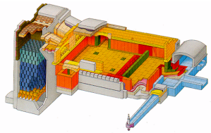
The purpose of a glass furnace is to bring the glass batch into a state of softening such as to be worked by molding machines. Figure 1 shows a typical glass furnace configuration, named End-Port (EP), used for the production of bottles, jars and small containers; this configuration is the most frequent for the medium and large facilities and for this reason is the subject of the investigation.
Figure 1. End-Port glass furnaces design
A glass furnace is composed by two main zones: the combustion chamber (CC) and the heat recovery system (HRS). In general the CC is a refractory oven where the molten glass pool (30-150 m^2) is heated by a combustion process and/or an electric charge. In most plants, the fuel used is natural gas; a further heat flow is introduced by means of electrodes, immersed into the glass, with the purpose of increasing the convective flows inside the glass bath. The raw material is introduced in the first part of the glass pool, the glass is heated up and stirred in the central part of the pool, the glass flow into a throat, in the final part of the CC, and is channeled to the production machines. The CC has at least a port for the combustion air access and a port for the exhaust gas release, as for the EP plants. The glass bath is heated up to temperatures that can reach 1700-1800 K, for this reason the exhaust gas leaves the CC at very high temperatures, 1400-1500 K; consequently, a glass plant cannot efficiently work without a HRS.
The HRS is a critical component, in general it is aimed at keeping part of the heat from the exhaust gases and release it to the combustion air; a HRS for glass plants must ensure good performance and low maintenance throughout the lifetime of the furnace (about 6-8 years) in extreme conditions of temperature, chemical aggression and dirt. The recuperative HRS uses a steal heat exchanger, shell and pipe or double shell types, this system can work continuously but, due to the steal temperature limitation, the combustion air cannot exceed 1100 K, thus the recuperative HRS heat performance, ratio between the heat released to the air and the exhaust gas heat , is less than 0,4. The regenerative HRS are more complex, expensive and large configurations but, using refractory materials, can overcome the limitations of the recuperative plants. A regenerative HRS for glass furnaces has at least two twins fixed bed chambers, as in the EP where the two regenerative chambers (RC) are positioned side by side: the air inlet and the exhaust outlet ports are positioned at the same side of the oven allowing the formation of the typical horseshoe shaped flame in the CC. The regenerative HRS can guarantee a continuous heat recovery with a cyclic inversion (every 20 min.) of the air and exhaust flows. During a cycle, the air flow is forced from bottom to top and heated by the refractories that had been heated by the exhaust gases in the prior cycle. The exhaust gases produced in the CC flow from top to bottom into the other RC and release their heat to the refractories that will be used in the next air cycle.
The air temperature in the regenerative HRS, due to the refractories materials, can reach values very close to the exhaust gas temperature; the recuperative heat performance can reach 0.6.
The WGR system is a primary technique for the abatement of NOx emitted from a glass furnace. The formation of the NOx, in the area concerned by the combustion process, is influenced by the combination of high temperature and high oxygen concentrations. The WGR system, by means of a strategic exhaust gas injection inside the air phase RC, allows the reduction of local concentration of oxygen where the early stages of combustion take place. The system is made by a physical connection between the two RCs by means of a circuit positioned in the lower part of the regenerator. A portion of flow is bled from the exhaust phase RC and it is introduced, by means of a blower, at the base of the air phase RC. A couple of three-way valves allows the reverse cycle for the air and gas phases of the RC.
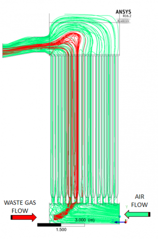
The WGR system coupled with the air phase RC is investigated using CFD with the aim of monitoring, for different geometries of the RC and WGR ducts, the path of the exhaust gases in the chamber to optimize the exhaust gas distribution.
Figure 2. WGR system coupled with the air phase RC: exhaust gas streamlines (red), air flow streamlines (green)
a) Top chamber
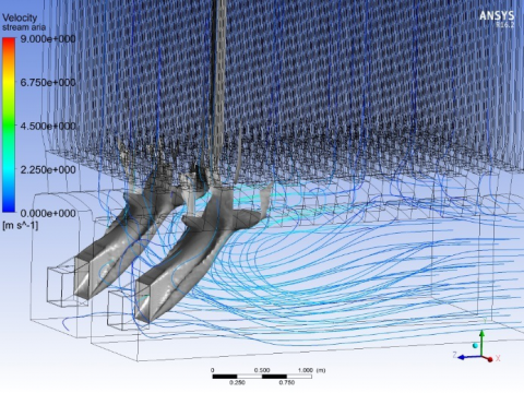
b) Bottom chamber
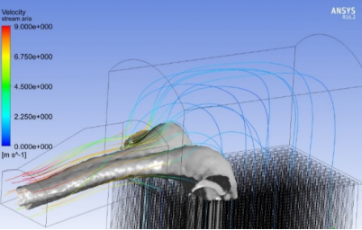
Figure 3. Iso-Surface at 16% O2 mass concentration (grey) and air velocity streamlines
The CFD model considers the entire geometry of the air phase RC of a demonstrator plant (within the Prime Glass project) using the methodology described in previous papers [4-5-6]. The RC Mesh is composed by three main parts: the bottom chamber, the checker zone and the top chamber. The fluid domain of the checkers zone is modelled using series of squared channels with 150 mm side to give a better approximation of the real checkers zone in the demonstrator plant. The heat exchange in the RC is modelled by distributing evenly the total heat flux (estimated by a thermal balance of the furnace) over the channel surfaces of the checkers zone.
The WGR system must create a poor oxygen area in the primary combustion zone therefore it must operate to concentrate the exhausts as close as possible to the sole of the top chamber outlet port, named port-neck. As shown in Figure 3, the design of the WGR circuit allows to control the O2 distribution into the CC.
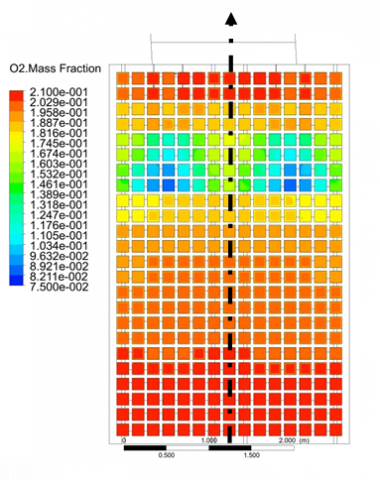
In addition to the NOx abatement, the injection of an exhaust flow in the air phase RC induces an increase of the heat flux absorbed by the flow due to the thermal radiation proprieties of the CO2 and of the H2O vapor content in the exhaust gases. This phenomenon is mainly influenced by the concentration of the above molecules; therefore, it is useful to track the oxygen concentration, inversely proportional to the exhaust mass fraction, on a control surface that cuts perpendicularly the checkers zone channels.
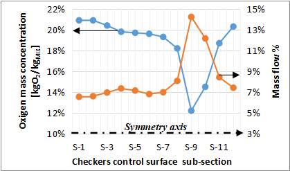
As is show in Figure 4 the O2 concentration profiles on the checkers control surface are symmetric with low values, indices of high exhaust mass fraction, in a well confined part of the checkers zone. The local data of Figure 4 can be post-processed to give more comprehensive information on the Oxygen distribution in the RC at a given operating point as shown in Figure 5.
The injection of exhaust gases in the air phase RC has positive effects on the total heat transfer due to the proprieties of the radiant gases, mainly CO2 and H2O vapor, present in the exhaust mixture. The CFD analysis previously described gives detailed information about the exhaust gases distribution inside the RC and confirms that, with a correct design, the WGR system can distribute the exhaust in well-defined patterns.
It is therefore interesting to develop a numerical model for the evaluation of the emissive properties of the gases that will be used for parametric analysis or implemented into 1-D models of the regenerator system as in [7].
In literature there are various methods for the prediction of radiant thermodynamic proprieties of gases, Lallemant reviews some of it in the first part of [8]. The largest part of the engineering methods is based on the experimental data acquired by Hottel and Cohen [9]. The method develop by Hottel is based on radiation heat emitted by a hemispherical gas mass to a surface element located at the center of the hemisphere’s base. With this experiment the gas emissivity can be formulated using the gas temperature and the product of the gas partial pressure per the hemisphere radius. The experiment results can be adapted for several different geometry using the right correlation for the calculation of the “equivalent hemisphere radius” or characteristic length l.
Figure 4. O2 mass concentration contours on the checkers zone control surface
Figure 5. O2 mass concentration and mass flow percentage on the checkers zone control surface
The Hottel’s graphs [10] show the emissivity value of H2O and CO2, Equations (1)-(2), at the atmospheric pressure in a temperature range between 300 and 2100 K and for pgl range between 0.001 and 10 atm * ft.
$\varepsilon_{\mathrm{h} 2 \mathrm{o}, 1 \mathrm{atm}}=\mathrm{f}\left(\mathrm{T}_{\mathrm{f}}, \mathrm{p}_{\mathrm{h} 2 \mathrm{o}} \mathrm{l}\right)$ (1)
$\varepsilon_{\mathrm{co} 2,1 \mathrm{atm}}=\mathrm{f}\left(\mathrm{T}_{\mathrm{f}}, \mathrm{p}_{\mathrm{co} 2} \mathrm{l}\right)$ (2)
The gas absorptivity, Equations (3)-(4), is calculated adopting the emissivity charts at the solid temperature and with a corrected characteristic length.
$\alpha_{\mathrm{h} 2 \mathrm{o}}=\left(\frac{\mathrm{T}_{\mathrm{f}}}{\mathrm{T}_{\mathrm{s}}}\right)^{0.45} * \varepsilon_{\mathrm{h} 2 \mathrm{o}}\left(\mathrm{T}_{\mathrm{s}}, \mathrm{p}_{\mathrm{h} 2 \mathrm{o}} \mathrm{l} * \frac{\mathrm{T}_{\mathrm{s}}}{\mathrm{T}_{\mathrm{f}}}\right)$ (3)
$\alpha_{\operatorname{co} 2}=\left(\frac{\mathrm{T}_{\mathrm{f}}}{\mathrm{T}_{\mathrm{s}}}\right)^{0.65} * \varepsilon_{\mathrm{co} 2}\left(\mathrm{T}_{\mathrm{s}}, \mathrm{p}_{\mathrm{co} 2} 1 * \frac{\mathrm{T}_{\mathrm{s}}}{\mathrm{T}_{\mathrm{f}}}\right)$ (4)
The gas mixture emissivity, and likewise its absorptivity, is the sum of the contribution of the emissivity of each radiative species to whom is subtracted a spectral overlap corrective factor, ∆ε , which takes into account the simultaneous presence of different radiant chemical species, as in Eq. (7).
$\varepsilon_{\mathrm{f}}=\varepsilon_{\mathrm{h} 2 \mathrm{o}}+\varepsilon_{\mathrm{co} 2}-\Delta \varepsilon$ (5)
$\alpha_{\mathrm{f}}=\alpha_{\mathrm{h} 2 \mathrm{o}}+\alpha_{\mathrm{co} 2}-\Delta \alpha$ (6)
$\Delta \varepsilon=\Delta \alpha=\mathrm{f}\left(R_{g}, \mathrm{p}_{\mathrm{g}} \mathrm{l}, \mathrm{T}_{\mathrm{f}}\right)$ (7)
$R_{g}=\frac{\mathrm{p}_{\mathrm{h} 2 \mathrm{o}} 1}{\mathrm{p}_{\mathrm{h} 2 \mathrm{o}} 1+\mathrm{p}_{\mathrm{co} 2} 1}$ (8)
The Hottel’s graphs [10] for the H2O and CO2 emissivity have been processed in order to obtain several polynomials of the emissivity as a function of the gas temperature at constant pgl . The overlap correction factor is modelled with a two variable polynomial, for Rg equal to 0.75 value typical of the glass furnace’s exhaust gases.
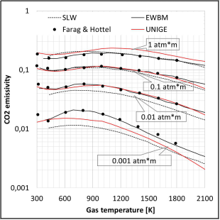
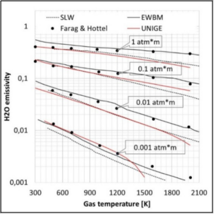
The emissivity model has been tested by comparing it with data found in ref. 8: figures 6 and 7 show, for the CO2 and H2O respectively, the emissivity model result compared to the experimental Farag and Hottel data and with a Spectral Line Weighted sum of gray gas model (SLW) and the Exponential Wide Band Model (EWBM).
Figure 6. CO2 emissivity model (UNIGE) compared with Farag & Hottel experimental data and other numerical spectral models
Figure 7. H2O emissivity model (UNIGE) compared with Farag & Hottel experimental data and another numerical spectral model
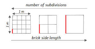
Figure 8. Scheme of the parametric investigation
The Hottel’s experimental results about the gas thermal radiance show a clear trend of the increase of emissivity with the pgl product. This means that the WGR thermal effect is located where the exhaust mass fraction is high, i.e. where low oxygen concentration is detected, secondly that the hydraulic diameter of the stacker channels can introduce an increase of the radiant effects. In this section a parametric analysis of the total heat transfer exchanged by the RC with different stacker channels hydraulic diameters is presented using the above gas emissivity model.
A portion of the volume in the checkers zone with a squared base area ($A_(base)$) of 1 m of side is considered, as it is show in figure 8, and it is divided in N squared cross-section channels without wall thickness. The investigated volume is than divided in 20 sections across the RC height.
A linear distribution of temperature across the RC height is set up for the refractories, Ts, and the fluid, Tf, as showed in Table 1. The pressure inside the regenerator is considered constant and equal to the ambient pressure; the ratio of the exhaust to the total mass flow is take as 20%: the radiant gases partial gas pressures are then constant and equal to 0.013 atm for the CO2 and 0.046 atm for the H2O.
The total heat flux transferred, $q_{t o t, i}^{\prime \prime}$ , in the air phase RC from the ith cell across the RC height is expressed by Eq. (8):
$q_{t o t, i}^{\prime \prime}=\frac{h_{t o t, i} A_{w e t}\left(T_{s, i}-T_{f, i}\right)}{A_{b a s e}}[\mathrm{W} / \mathrm{m} 2]$ (9)
Where htot,i is the total heat transfer coefficient and Awet is the wetted surface. By expressing Awet as a function of the wetted perimeter pwet the total volumetric heat flux $q_{t o t, i}^{\prime \prime \prime }$ can be expressed by Eq. (9):
$q_{t o t, i}^{m}=h_{t o t, i} p_{w e t}\left(T_{s, i}-T_{f, i}\right) \quad[\mathrm{W} / \mathrm{m} 3]$ (10)
According to the Eq. (9) the total volumetric heat flux, $q ̇_(tot,i)$ , is proportional to the product of the wetted perimeter, the total heat transfer coefficient and the temperature difference potential.
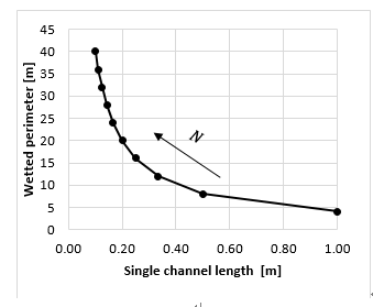
Referring to the scheme in Figure 8, the pwet value strongly decreases with the channel length, lch increase: as from Eq. (10) (shown in Figure 9) there exist an inverse proportionality between the two variables.
$p_{\text {wet}}=4 / l_{c h}=4 N$ (11)
Figure 9. Wetted perimeter varying the brick length
The $h_(tot )$ value can be considered as the sum of a convective, $h_(conv )$ , and a radiant, $h_(rad )$ , contribution.
The $h_(conv )$ within the air phase is a complex phenomenon where forced and natural convection regime are combined. Specific CFD analysis have been done by the authors in [4] to model the heat transfer in a conventional regenerator system; in the above reference, the convective heat transfer coefficient profile across the air phase inside the RC is calculated for a single channel that forms the checkers zone. In the present analysis, a linear $h_(conv )$ profile is considered ranging from 8.2 W/m2K at the bottom to 3.2 W/m2K at the top [4].
Table 1. Refractories and fluid temperature profiles
|
|
BOTTOM |
TOP |
|
|
$T_s$ |
800 |
1350 |
K |
|
$T_f$ |
450 |
1250 |
K |
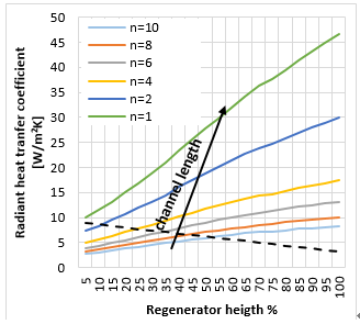
Figure 10. Radiant heat transfer coefficient over the regenerator height at WGR 20%
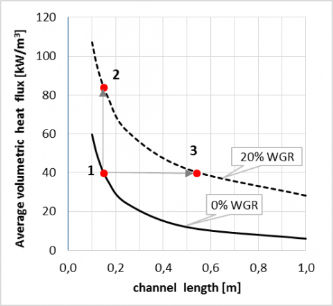
Figure 11. Average volumetric heat flux comparison between WGR 20% and WGR off at different channel
The $h_(rad )$ can be calculated, for each cell height, using the emissivity model from Eq. (11).
$h_{\text {rad }, i}=\sigma\left(\varepsilon_{\text {fi }} T_{\text {f,i }}^{4}-\alpha_{f} I_{s, i}^{4}\right) /\left(T_{\text {fin }}-T_{s, i}\right) \quad\left[^{W} /_{\text {m }^{2} K}\right]$ (12)
Figure 10 shows the trend of the radiant heat transfer coefficient profiles with different values of N . The positive effect on the heat transfer from the channel length increase is evident. The volumetric heat flux, $q_{t o t , i}^{\prime \prime}$, can be calculated along the regenerator height using Eq(8) for different value of N . Figure 11 compares the total volumetric heat fluxes (averaged along the regenerator height) with or without WGR system activation. It can be observed that the average volumetric heat flux is positively influenced by the activation of WGR system; it allows, in any condition, an increase in the thermal transfer performance. The curves show, for both operating conditions a heat flux decrease with the increase of the channel length; this is due to the strong decrease of the wetted perimeter, i.e. the thermal transfer surface.
Some useful conclusions can be drawn:
As an example, referring to Figure 11, in a conventional regenerator system (point 1) with a channels length of 150 mm, in case of a WGR system activation (point 2), the volumetric heat transfer can be doubled in zones with high level of exhaust gases.
In the same condition, the thermal performance can be maintained (point 3) with larger channels (about 550 mm) with a refractory material saving greater than 70%.
In this paper, a WGR system applied to an End-Port type regenerative glass furnace is analyzed. A CFD methodology for the study of the WGR system and its optimization to the regenerative HRS has been presented. The CFD analysis has proven to be a valuable tool for the fluid dynamic analysis of the system WGR coupled to a regenerative system, in particular for the tracking of the flue gas passing through the stackers zones, until they leave the top chamber.
A numerical model for the radiant gas emissivity has been developed and validated comparing the results with experimental data and spectral numerical models. The emissivity model has been useful to understand how a geometrical change in the RC channels can affect the heat transfer in case of WGR activation.
The preliminary thermodynamic analysis confirms an increase of the total heat transfer due to the radiant effects of the exhaust gases in the air phase RC. Moreover, in case of WGR activation, an increase in the channel length implies an increase of the total heat transfer coefficients and a reduction of the volumetric heat transfer performance due to the reduction of the heat transfer surface. In conclusion, the WGR system, in addition to its primary function of NOx abatement [3, 6] can increase the heat transfer performance of the regeneration system compared to the system without WGR.
These models and the CFD applications to glass industry presented have been developed by the University of Genova team within the PRIMEGLASS European Project (LIFE12 ENV/IT/001020) framework.
|
WGR |
Waste Gas Recovery |
|
EP |
End-Port |
|
CC |
Combustion Chamber |
|
HRS |
Heat Recovery System |
|
RC |
Regenerative Chamber |
|
CFD |
Computational Fluid Dynamics |
|
SLW |
Spectral Line Weighted sum of gray gas model |
|
EWBM |
Exponential Wide Band Model |
|
T |
temperature [K] |
|
p |
pressure [atm] |
|
l |
characteristic length [m] |
|
R |
partial pressure per length ratios |
|
q |
heat flux [W] |
|
h |
heat transfer coefficient [W/m2K] |
|
N |
Number of channel per side |
|
M |
Number of cells of the RC in height |
|
Greek symbols |
|
|
α |
absorptivity |
|
δ |
Stefan-Boltzmann constant |
|
Subscripts |
|
|
s |
solid (refractories) |
|
g |
radiant gas |
|
tot |
total |
|
wet |
wetted |
|
ch |
channel |
|
base |
investigated base |
[1] Scalet B.M., Garcia Mùnoz M., Sissa A.Q., Roudier S., Delgado Sancho L. (2013). JRC reference report - best available techniques reference document for the manufacture of glass, Industrial Emission Directive 2010/75/EU (Integrated Pollution Prevention and Control), http://eippcb.jrc.ec.europa.eu/reference/BREF/GLS_Adopted_03_2012.pdf
[2] Life project “LIFE 12 ENV/IT/001020” web page: http://ec.europa.eu/environment/life/project/Projects/index.cfm?fuseaction=search.dspPage&n_proj_id=4526&docType=pdf%22
[3] Prime Glass Life Project web site: http://www.primeglass.it/
[4] Cravero C., Marsano D. (2017). Numerical simulation of regenerative chambers for glass production plants with a non-equilibrium heat transfer model, Conference on Energy, Enviroment, Ecosystem and Sustainable Development, Roma, WSEAS Transactions on Heat and Mass Transfer, ISSN / E-ISSN: 1790-5044 /2224-3461, Vol. 12, Art. #3, pp. 21-29.
[5] Basso D., Briasco G., Carretta M., Cravero C., Mola A. (2014). CFD simulation of regenerative chambers in glass industry to support the design process for thermal efficiency improvement, Int. CAE Conference, Pacengo del Garda (Italy), pp. 27-28.
[6] Basso D., Cravero C., Reverberi A.P., Fabiano B. (2015). CFd analysis of regenerative chambers for energy efficiency improvement in glass production plants, Journal Energies, Vol. 8, No. 8, pp. 8945-8961. DOI: 10.3390/en8088945
[7] Cravero C., Marsano D., Spoladore A. (2017). Numerical strategies for fluid-dynamic and heat transfer simulation for regenerative chambers in glass production plants, NAUN International Journal of Mathematical Models and Methods in Applied Sciences.
[8] Lallemant N., Sayre A., Weber R. (1996). Evaluation of emissivity correlations for H2O-CO2-N2/Air mixtures and coupling with solution methods of the radiative transfer equation, Prog. Energy Combust Sci., Vol. 2, pp 543-574, Elsevier.
[9] Hottel H.C., Cohen E.S. (1958). Radiant heat exchange in a gas-filled enclosure: Allowance for nonuniformity of gas temperature, AIChE J., Vol. 4, pp. 3-14. DOI: 10.1002/aic.690040103
[10] Bergman T.L., Incropera F.P., DeWitt D.P., Lavine A.S. (2011). Fundamentals of heat and mass transfer, John Wiley & Sons.