OPEN ACCESS
In this paper is presented an industrial drier developed, prototyped, tested and analyzed to produce selected aggregates for the construction industry, for a localized and specific production line for the treatment of natural or recycled aggregates. The short production of premixed powder, through the exploitation of local and recycled aggregates, has highlighted the need to design an efficient drying system. The prototype developed as a drier (Screw Conveyor Drier-SCD) with screw at an angle of 20°, 2000 x 3685 mm 7070 x size, isolated outside of indirect heat exchange. The fluid exchanges heat in the circuitry that runs through the inside of the shaft and the outer sleeve of the auger. The type of heat source is not binding; therefore, sources of renewable energy or waste heat can be used, even at low specific enthalpy. During experimental analysis, hot water was used at a maximum temperature of 80 °C and sand with 5-6% moisture input was processed for a flow rate of 2 tons/h. Experimental results have shown, in a two-stage step, a reduction in the humidity up to 30% compared to the initial value and a maximum temperature of 31 °C in solid output. The analysis of experimental results and the data obtained from thermodynamic simulations have shown that the system performance can be optimized through specific improvements of the mechanical parts.
thermodynamic analysis, prototype screw indirect drier, recycled aggregates
The production of short-range premixed powder, through the exploitation of local aggregates and recycled aggregates, has given rise to the need for an efficient drying system.
Experimentation has shown that the ordinary process of preparation of the aggregates, in particular in the phase of drying prior to their selection, prove absolutely inadequate for the production of material.
This theme of efficiency and industrial sustainability has been addressed in collaboration with the Personal Factory S.p.A. of Vibo Valentia, the only company worldwide supplier of integrated systems for the production of pre-mixed powder.
The classic drying processes can be harmful in the case where in the component to be dried there are traces of organic components that are not eliminated by the previous processes. At the same time, the classical systems are designed for large-scale drying and are not eligible to a localized production nor flexible to different operating conditions. These considerations have led to the design of an indirect type of drying system that combines low running costs, reduced environmental impact and increased energy efficiency through the possibility of using different energy sources.
The ultimate goal is, therefore, to facilitate and stimulate economic and business growth, to use and recycle local resources, while avoiding environmental degradation.
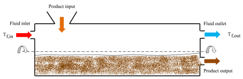
The aggregates used for the production of pre-mixed powder for the building must necessarily be free of moisture, as with all the materials that make up the finished product, and they should be suitably screened [1], [2]. The most widely used industrial systems for drying aggregates are those with a rotary drum, the so-called direct systems (Figure1).
Figure 1. Diagram of a cocurrent rotary drum drier
Inside the rotary drum are mounted various types of blades, suited for overturning, advancement and high yield, which favor the thermal exchange, generally between hot gases and the materials to be dried.
Such systems have a very limited use:
- small plants for small productions are economically unsustainable;
- they are highly energy-consuming because they require high power sources to reach the thermal temperature of the heat transfer fluid;
- inflexible use of renewable thermal sources;
- low energy efficiency if not coupled with cogeneration systems;
- risk of alteration of the material caused by high temperatures;
- environmental risk and safety problems due to the high temperature gas in direct contact with the material.
It was considered, therefore, appropriate to undertake the task of designing an innovative and alternative drying system that combined:
- low environmental impact and the absence of a direct flame;
- inexpensiveness of the system with a construction cost on a competitive scale;
- high tolerance to incoming raw materials;
- good tolerance to moisture input;
- easy maintenance and installation;
- ability to use multiple energy sources;
- low operating temperature, and with a drier that is not energy-intensive, even given the very low output value that the recycling of aggregates and drying require on-site.
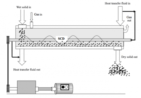
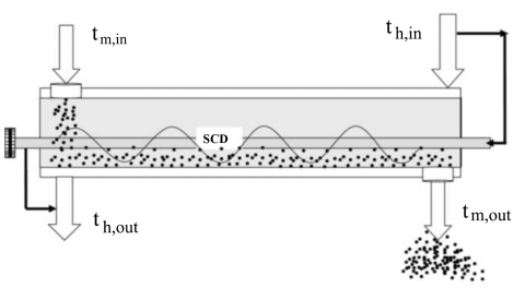
Figure 2. Scheme of a direct and indirect auger drying system.
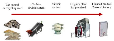
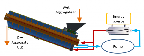
Figure 3. Production process from wet to dry premix finished inert.
By virtue of the needs of the project and required characteristics, it was decided to design, prototype, and test a drier auger, denominated in the literature SCD (Screw Conveyor Drier), where the heat transfer fluid exchanges heat indirectly with the material to be dried [3], [4].
Figure 2 shows a diagram of a drier auger where heat exchange is direct or indirect.
Auger drier systems are an emerging technology in the industrial market but are finding a growing interest by virtue of their characteristics. In industrial processes, it is often necessary to convey the material and, at the same time, warm or dry it. This is the case of the aggregates (by recycling or not) for premixing in building construction, where the material must be dried and transported to a sieving station, for the materials to be used to be suitably selected (Figure 3).
In heat exchangers of indirect type auger, the thermal efficiency is given by the following relationship:
${{\eta }_{T}}=\frac{heat\,absorbed\,from\,material}{heat\,furnished\,from\,fluid}$ (1)
The thermal power absorbed by the material is divided into sensible power, which is necessary to increase the temperature of the material, and in latent power for the vaporization of the moisture content in the material:
Qm = Qm,sens + Qm,lat [W] (2)
Qm,sens = Gm · ρm · cm · ( tm,out - tm,in ) [W] (3)
Qm,lat = GV · ρv · λlat (4)
where Gm [m3/s] is the volumetric flow rate of the dry material and GV [m3/s] is its vapor content, ρm [kg/m3] is the material density e ρv [kg/m3] is the density of water vapor, cm [J/(kg K)] is the specific heat of the dry material mediated between the inlet and outlet temperatures of the solid from the drier tm,out and tm,in [°C], while λlat [J/kg] is the latent heat of vaporization of water.
In steady state conditions, the thermal power absorbed by the material is equal to the actual thermal power transferred from the heat transfer fluid, equal to:
Qm = Ut · Aeff · △Tlm [W] (5)
where $U_t$ [W/(m2 K)] is the global coefficient of heat exchange of the drier, $A_eff$ [m2] is the effective area of heat exchange, △Tlm [°C] is the logarithmic temperature difference between incoming and outgoing heat transfer and fluid material. These three parameters determine the drier ability to transfer heat to the material to be dried.
The overall heat transfer coefficient of the drier $U_t$, is a very important parameter according to the type of material to be dried, the drier characteristics and the heat transfer fluid. The theoretical calculation of this coefficient is determined by several factors. In the case of a drier of the indirect type, the heat transfer fluid flowing in the shaft and in the auger shirt. For a better understanding we distinguish between two different coefficients of transmission, one for the drier jacket Uco, and the other for the auger Ucam, which can be calculated as follows:
$\frac{1}{\mathrm{U}_{\mathrm{co}}}=\frac{1}{\mathrm{h}_{\mathrm{co}, \mathrm{f}}}+\frac{\mathrm{s}_{\mathrm{alb}}}{\lambda_{\mathrm{alb}}}+\frac{1}{\mathrm{h}_{\mathrm{co}, \mathrm{m}}}\left[\frac{\mathrm{m}^{2} \mathrm{K}}{\mathrm{W}}\right]$ (6)
$\frac{1}{\mathrm{U}_{\mathrm{cam}}}=\frac{1}{\mathrm{h}_{\mathrm{cam}, \mathrm{f}}}+\frac{\mathrm{s}_{\mathrm{cam}}}{\lambda_{\mathrm{cam}}}+\frac{\mathrm{s}_{\mathrm{m}}}{\lambda_{\mathrm{m}}}+\frac{1}{\mathrm{h}_{\mathrm{cam}, \mathrm{m}}}\left[\frac{\mathrm{m}^{2} \mathrm{K}}{\mathrm{W}}\right]$ (7)
where hco, f, hco, m, hcam,f, e hcam,m [W/(m2 K)] are the convective coefficients respectively between the screw and fluid, between the screw and the material, between shirt and fluid and between shirt and material; salb [m] and scam [m] are respectively the shaft and thicknesses of the cylinder and λm, λalb e λcam [W/(m K)] are the conductivity for the material, the shaft and the drier jacket. The coefficients of convective heat transfer fluid hco, f and hcam, f can be evaluated from the technical literature. On the contrary, the convective coefficients of the material with the drier hco,m and hcam,m, are not easily calculable. For this reason, the overall coefficient of heat exchange Ut is achieved only with experimental test. The values of Ut are relatively low compared to other heat exchange systems, from a minimum of a few units up to values generally not exceeding 100 W/(m2 K).
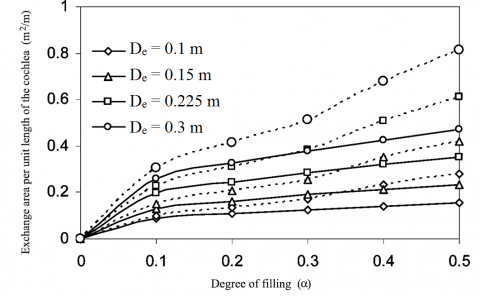
The effective area of heat exchange Atot is determined by the geometrical dimensions of the drier and in particular by the diameter of the auger, but above all by the degree of filling. The latter is an important factor in SCD systems, which must be chosen according to the characteristics of the material and it affects handling, flow rate and degree of drying. For granular minerals, the recommended values, and those used in the literature, are in the range 0.15 to 0.45. In this range two important factors are guaranteed: efficiency in transporting all the material towards the exit and mixing and then heating it with homogeneity.
In the case of a completely hollow auger, in both the shaft and the coils, the heat exchange area greatly increases, as shown in Figure 4. Considering the most common case, in which there is no passage of fluid in the auger but only the shaft appears cable, using an efficiency factor:
$\eta_{\mathrm{sp}}=\frac{\tanh (\mathrm{x})}{\mathrm{x}}$ (8)
$x=\beta \cdot \ell$ (9)
$\beta=\left(\frac{\mathrm{h}_{\mathrm{co}, \mathrm{f}} \cdot \mathrm{P}_{\mathrm{e}}}{\lambda_{\mathrm{sp}} \cdot \mathrm{S}_{\mathrm{e}}}\right)^{0,5}$ (10)
where φ, Pe and Se are respectively the length, the perimeter and the section of the coils.
The SCD-type systems have the peculiarity of ensuring a wide heat exchange surface. For a drier to cables auger shaft, the total heat exchange area can be calculated through the following expression:
$\mathrm{A}_{\mathrm{tot}}=\mathrm{A}_{\mathrm{cam}}+\mathrm{A}_{\mathrm{alb}}+\eta_{\mathrm{sp}} \cdot \mathrm{A}_{\mathrm{sp}}\left[\mathrm{m}^{2}\right]$ (11)
The variation of temperature of the material to be dried and of the heat transfer fluid follow a logarithmic trend. Therefore, for the calculation of the heat flow, using the variation of the logarithmic average temperature ΔTlm typical of heat exchangers (Figure 5):
$\Delta \mathrm{T}_{\mathrm{lm}}=\frac{\left(\mathrm{t}_{\mathrm{h}, \mathrm{out}}-\mathrm{t}_{\mathrm{m}, \mathrm{in}}\right)-\left(\mathrm{t}_{\mathrm{h}, \mathrm{in}}-\mathrm{t}_{\mathrm{m}, \mathrm{out}}\right)}{\ln \left(\frac{\mathrm{t}_{\mathrm{h}, \mathrm{out}}-\mathrm{t}_{\mathrm{m}, \mathrm{in}}}{\mathrm{t}_{\mathrm{h}, \mathrm{in}}-\mathrm{t}_{\mathrm{m}, \mathrm{out}}}\right)}$ (12)
Figure 4. Effective area of heat exchange for full or totally empty screw.
Figure 5. SCD indirect: temperature of the solid and the fluid at the inlet and at the output.
Figure 6. Psychometric diagram quality of a gas flow in an indirect SCD.
The degree of drying is a key determinant of SCD systems and varies as a function of the working conditions. A flow of gas inside the drier, with the sole purpose of transporting the evaporated moisture away from the material, is an important factor. The flow of gas can enter and exit from the drier extremes and be cocurrent or countercurrent with the motion of the material to be dried [5], [6].
In both cases, the gas, entering at room temperature, increases its temperature at the exit, as shown in Figure 6. In the case of cocurrent flow as well as an increase in temperature it will also have a relative humidity decrease (curve 1-2-3). In the case, instead, of countercurrent flow, the gas will increase as the temperature will also increase its relative humidity (1-4-5 curve).
This phenomenon leads to a rapid saturation of the gas which prevents the steam transfer from the gas to the material. In fact, in the initial part of the auger the material is not subject to drying. It follows that the cocurrent gas flow has a higher degree of drying than the countercurrent.
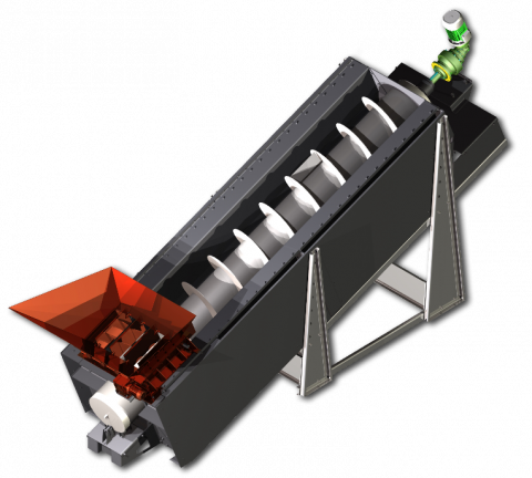
The design of the mechanical parts followed the specifications of the project was completed through the use of 3D modeling software, Autodesk Inventor. The total drier dimensions are 7070 x 2000 x 3685 mm, with an inclination of 20° of the auger (Figure 7).
Figure 7. Rendering of prototype drier
The drier is composed of an inner tub, which constitutes the auger housing and the heating jacket, formed by an upper lid, from four welded half-tanks and 2 external flanges. The flange at one end acts as an outlet of the dried material. At the inside of the bath it is coupled to an outer tub, consisting of a lid, from four half-tanks welded flanges and four, two of which are internal, which in turn in the assembly are integral with the frame of the drier. Inside is placed a shaft of 600 mm diameter auger cable, for a total length of 6 m. The diameter of the coils is 1 m, with a pitch of 250 mm at a loading mouth, and 500 mm step for the remaining 9 turns.
Once both the tanks and the auger are assembled, the seals are installed for the aforementioned mechanical parts. The auger shaft, free to rotate, is supported by two supports, one for the lower end and the other for the upper end. The first is constituted of three type L rollers, a plate support and a vertical support for a roller. The second by two rollers, plate di support and struts. The supports and the rollers have been chosen and dimensioned according to the pipes structural calculations.
At the extremity of the highest place in the auger motor and gearbox were linked and provided with inverters which are sized and selected to ensure a maximum speed of 4 rpm and a minimum close to 0.5 rpm with the two components having the following characteristics: angular planetary gearmotor 4-stage with 4-pole motor; output speed 4 rpm; reduction ratio 363; 0.88 yield; Motor of 5.5 kW; 11714 Nm in torque output.
At the bottom side of the auger a removable loading hopper with quick coupling is positioned. Its total carrying capacity is 1 m3. There are four exhaust valves, with gearmotor worm and with pre-stage and output speed of 3.5 rpm.
The frame was designed following the inclination of the apparatus and is integral to three of the outer tub flanges, while the flange at the lower end rests directly on the ground. The tub is closed by a flat and slightly sloping roof with respect to the ground so that any condensation slides to the lower end where there is a drainage channel. Instead, on the upper side a ventilation grid is positioned to release the air with accumulated water vapor. (Figure 8).
Figure 8. Mechanical parts of carpentry of the drier prototype auger
Initially the functionality and the kinematic system was tested with sand and the system cold. The sand came without machine downtime and continuous along the whole path, from the entrance of the hopper to the mouth of the upper flange output, while the opening and closing systems of the exhaust valve worked correctly; the kinematics of the auger handling did not present any hitches. The shaft revolved properly supported by the supports with rollers without having derailing. The auger was handled under gearmotor and inverter, alternating the rotation speed without discontinuity.
Once the mechanical operation was tested, the design was completed and the distribution channels of the heat transfer fluid implemented (Figure 9).
Figure 9. Representation of the distribution circuit of the heat transfer fluid.
Inside the shaft and the auger shirt there are two groups of discharge tubes. For the shaft, the tube is placed at the center of the same while the shirt is placed in the lower part. At the extreme bottom of the two tubes the hot fluid enters, and then is downloaded to the opposite extreme, that is, the higher side of the auger. Flanked to the hot fluid inlet area, and that is, still from the lower side of the drier, are placed the outputs of the fluids from the drier. Inside the shaft a flow of 2.3 m3/s of fluid circulates while in the jacket, the volume is 2.8 m3 but filled only to 95%. The two zones, shirt and shaft, where the hot fluid exchanges heat, are sealed. Both in the jacket and in the shaft there are two safety valves to compensate for excess pressure and excess volume of the heat transfer fluid caused by high temperatures.
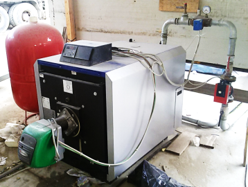
This system protects the mechanical parts that have many welds, which are likely to be damaged in the case of high fluid pressure. To ensure proper rotation of the auger a rotary joint was inserted with internal gears in order to have balance between rotation of the shaft and that of the two output channels, and water intake (Figure 10). In addition, a suitable thermal source was dimensioned in order to ensure the flow of hot water for drying in the test phase, i.e. a boiler with the possibility of being fed both oil or gas, with useful power equl to 120 kW (Figure 11).
For the test LPG was used as fuel.
Figure 10. Rotary coupling for the distribution circuit of the fluid in the shaft
Figure 11. Boiler fueled by LPG for heating the water in the test phase
After the initial startup of the machine, some improvements were made to overcome the problems encountered: the diameter of the coils were reduced to increase the clearance between the coils and shirt, passing from 2 cm to 4 cm; the seals of the coupling were suitably reinforced, while the inverter was replaced by a larger one and the power of the engine support was improved.
Once the changes were made, a further complete test was carried out. The auger was loaded with material with a degree of filling of 0.2 at a speed of 0.5 rpm, which corresponds to a volumetric flow rate 1.45 m3/h, which, for dry density sand equal to about 1.4 ton/m3, corresponds to a design parameter of 2 ton/h.
There were no mechanical problems of any kind and the material traveled the entire stretch of the drier continuously. In addition, for a short time a lower rotation speed was tested, with no observed reduction of motion problems. It was however preferred to maintain the speed of 0.5 rpm to perform the complete test. The inlet water was brought to 80 °C. The sand took about 20 minutes to travel around the channel. The results showed a low moisture reduction, which from 5.5% input value, after two passages inside the drier, has undergone a reduction of up to 4.4% of the value at the output.
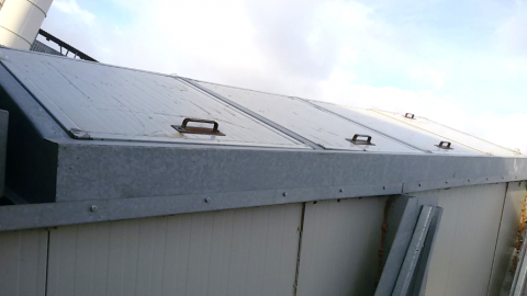
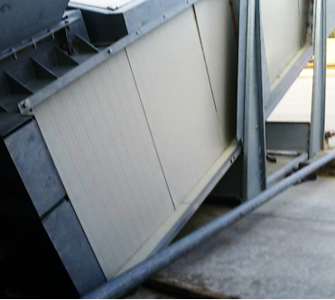
To improve the thermal insulation of the system, an insulating casing was applied made from sandwich 4 cm panels in EPS and divided into two zones, one to wrap the outer tub of the auger, the other applied to the sloped roof (Figures 12 and 13).
Figure 12. Cover insulating sandwich panels on the sloped roof
Figure 13. Cover insulating sandwich panels for the outer tub to the auger
In addition, the junction fins were installed between one coil and the other, to optimize the transport from the bottom to the top of the material.
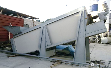
The drier with the new changes is shown in Figure 4.
Figure 14. Prototype of an auger drier of the Personal Factory
Once the latest devices were implemented, a second round of full test was carried out by setting the same conditions as the previous test. Also in this test, the material still moved too compact, this condition also being evident at the flange of the output material. The coupling with internal gears, for the return and the flow of water inside the shaft, constitute an obstruction for the entire circulation circuit in the shaft, owing to the small size of the internal channels. The result was therefore a lower water flow in the shaft than the shirt. The results did not differ much from the previous test. The outlet temperature of the material was on average 31 °C. A low moisture reduction was again observed, which from 5.7% at the input, after two passages inside the drier was reduced to 4.0%, corresponding to a reduction of 30% compared to the initial value.
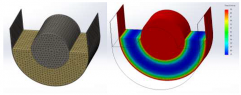
To analyze the thermal behavior of the material inside drier a series of simulations were carried out using CFD software, in order to highlight the heating of the same in function: of the temperature of the water passing through the jacket and the shaft of the auger, of the characteristics of the material in terms of chemical characterization, moisture, thermal capacity and thermal conductivity, of the rotation of the auger and therefore the residence time of the sand inside the dryer [7], [8] and [9].
To create the model we used a triangle mesh. By performing a series of analyzes as a function of the gauge and size of the mesh, the appropriate network nodes were identified which did not involve significant changes in the results compared to models with more nodes.
Figure 15. Simulation of conductive heat transfer by means of CFD analysis
There have been a series of simulations to vary the characteristics of the physical model, in order to determine the average temperature of the material. The simulations with meaningful data are reported in Table 1.
Table 1. Material properties and results of simulations
|
Sand |
cp [J / (kg K)] |
λm [W / (m K)] |
T [°C] |
Δt [min.] |
tm,out [°C] |
|
1: UR 20% |
2000 |
2,7 |
70 |
20 |
26 |
|
2: UR 0% |
800 |
0,35 |
70 |
20 |
20 |
|
3: UR 6% |
840 |
1,0 |
70 |
20 |
25 |
|
4: UR 6% |
840 |
1,0 |
70 |
25 |
27 |
|
5: UR 6% |
840 |
1,0 |
70 |
400 |
58 |
|
6: UR 6% |
840 |
1,0 |
120 |
20 |
43 |
|
7: UR 6% |
840 |
1,0 |
120 |
25 |
46 |
|
8: UR 6% |
840 |
1,0 |
120 |
200 |
91 |
Simulations 3 to 5 refer to the thermal conditions of the sand near to those of the actual tests. Simulation 3 had a final time of 20 minutes, corresponding for the actual test to the average stay of the sand in the auger. The average final temperature is tm,out = 25 °C, for a ΔT = 10 °C, which compared to the real case, tm,out = 31 °C, for a ΔT = 15 °C, differs by 6 °C . From the final values of average temperature it can therefore be assumed that the convective heat exchange component weighs only one-third the value of the total heat transfer coefficient Ut of drier, a low influence, owing to the low speeds of rotation and to the poor movement of the sand.
In the evaluation of drying capacity, it is important to stress that the temperatures involved have no way of reaching the boiling point of water, therefore the action of drying of the sand is achieved by evaporation due to difference of water partial pressure contained therein with respect to the air in the desiccator vapor pressure. The air inside the drier is about 6 m3, and can reach a temperature greater than or equal to that of the sand, as it is also in contact with the shaft and shirt heat exchange surfaces, and especially the thermal capacity of the air is nearly two orders of magnitude lower than the thermal capacity of the water, therefore, the air undergoes a much more rapid temperature increase than the sand. The sand inside the drier is located at an average temperature between 15 °C inlet and 30 °C outlet.
Therefore, it appears that:
$\mathrm{q}=\lambda_{\mathrm{lat}} \cdot \dot{\mathrm{m}}_{\mathrm{acq}}=\mathrm{S}_{\mathrm{c}} \cdot \mathrm{h}_{\mathrm{cv}} \cdot\left[\mathrm{p}_{\mathrm{v}, \mathrm{sat}}\left(\mathrm{T}_{\mathrm{s}, \mathrm{s}}\right)-\mathrm{p}_{\mathrm{v}, \mathrm{air}}\left(\mathrm{T}_{\mathrm{air}}\right)\right]$ (13)
where Sc [m2] is the contact surface between the sand and air, hev is the coefficient of evaporative heat exchange that for the air under static conditions is equal to 0.05 (W. m-2. Pa-1), Ts,s, is the surface temperature sand contact while the two pressures, pv,sat and pv,air [Pa] are calculated by knowing the values of temperature and relative air humidity ϕ input:
$\mathrm{p}_{\mathrm{v}, \mathrm{sat}}\left(\mathrm{T}_{\mathrm{s}}\right)=\mathrm{A} \cdot 10^{\frac{\mathrm{a} \cdot \mathrm{T}_{\mathrm{s}}}{\mathrm{b}+\mathrm{T}_{\mathrm{s}}}}$ (14)
$\mathrm{p}_{\mathrm{v}, \mathrm{air}}\left(\mathrm{T}_{\mathrm{a}}\right)=\phi \cdot \mathrm{p}_{\mathrm{v}, \mathrm{sat}}\left(\mathrm{T}_{\mathrm{a}}\right)$ (15)
The flow of the dried water, according to this formula, even considering optimal cases of superficial temperature of the sand of 30 ÷ 50 °C and initial completely dry air, is of the order of some units of a gram per second, a value confirmed in experimental data of drier. Conversely, owing to a sand flow rate of about 2 ton/h, the flow rate of incoming water is of a higher order of magnitude, namely of 30 g/s. It is thus understandable that the degree of drying is much lower than the total flow rate of moisture to be removed from the input material.
In the present work, an indirect drying plant in the auger was designed and prototyped, suitable for the local production of aggregates and recycled aggregates for building.
The realization of the prototype and the results of tests carried out have demonstrated the feasibility of the drier and the satisfaction of the main specifications of use. Exploiting a method of indirect drying and low specific enthalpy, there are no safety or environmental risks that may be generated in the presence of organic materials or residues. The drier has the flexibility in being able to take advantage of heat from different heat sources, with hot water at a temperature between 80 and 95 °C, widely available or easily generated in many different cases.
The plant is ecologically sustainable, unlike traditional systems, because the low temperatures requests can also come from the use of renewable biomass and solar thermal sources or from thermal sources of waste, otherwise not used.This plant contributes to reducting air pollution [ 10]. Since there is no need to make changes to existing installations, the installation is adaptable as a function of the installation location.
The auger handling system allows the evolution of moisture contained in the material to be monitored during the drying process, providing the possibility of evaluating and deciding dynamically the transit speed and the dwell time of the material inside the drier. Such an apparatus can be inserted upstream of a screening system of the aggregates able to process even large pieces of material.
The maintenance of the system is very simple and feasible even in difficult places, being constituted of a single motor and standard circuitry. The results of the first experimental tests have highlighted the need for further changes, while the analyzes conducted show large margins for improvement. The parameters to improve in the first place are surely the exchange of materials and seals which, starting from this first prototype which has undergone numerous modifications and adaptations, can be optimized by improving the heat exchange between the heat transfer fluid and material to be dried. Moreover, by using mixtures with ethylene glycol or sodium chloride, the temperature range of the fluid working may be expanded, up to 140-160 °C, thus increasing the heat flow towards the material, while at the same time the cheapness the solution. The addition of a passive gas stream inside the drier with the purpose of transporting the evaporated moisture away from the material, can increase the degree of drying, especially if this was the incoming and outgoing gas from the drier and cocurrent with the flow of material. This would facilitate the movement of moisture away from the material to be dried and would allow a structural optimization of the cover.
The modification to the cover and the ventilation mechanism through the passive gas flow would allow the shirt profile to be changed and optimized, even when changing from a profile from U to cylindrical, and make it possible to increase the heat exchange surface, increase the volume of fluid heat transfer and improve the insulation of the roof. The modification of the coil of the auger, with a reduction step, would allow further movement of the sand, by increasing the rotation speed but keeping the flow rate constant, thereby increasing the coefficient of heat exchange by convection between the heated wall and the material to be dried. The addition of new fins and arms between one coil and the other, with a suitable profile as a function of the new windings to the shorter wheelbase, would increase the handling of the sand, uncompacting it and ensuring proper aeration, which is necessary to facilitate the vaporization and subsequent moisture removal. The increase in the flow of the heat transfer fluid in the circuits, starting from modification of the kinematic joint for the shaft would allow a substantial increase in the convective heat transfer coefficient between the fluid and the heating shaft wall and the auger shirt.
The future aim will therefore be to finalize the optimization of the heat exchange and the necessary adaptation of the mechanical organs, until obtaining satisfactory results, then to move on to the patenting phase and subsequent ultimate commercialization of the machinery. To this end, with regard to the characteristics and the adaptability to a variety of implant applications, it will be important to activate the incentive systems of energy efficiency certificates. Abroad, however, the consent of a French public agency ADEME (Agency for Environment and Energy Management) has already been obtained to finance 70% of the project and parallel purchase of machinery by a potential customer in the island of Martinique. In addition, the presentation of the system at the "Stone Waste Recycling"seminar, at the Marmomacc 2014 in Verona, has created a strong interest among companies, mostly foreign, which mine and cut marble blocks and slabs from quarries.
The waste in large amounts of aggregates from the quarrying of marble and granite, but especially those from cutting, at the exit of the filter-press systems, generate a high cost of disposal and waste production. The drying plant enables the transformation of this noble waste material, combining environmental sustainability and economic gain. With regard to the necessary aggregate screening system, to be placed downstream of the drying system, a variety of screening lines have already been designed and two plants supplied for two different applications. Market analyses have allowed the Personal Factory to find an interesting application of machinery for drying of another type of material. Three of the many owners of gasifiers present in the area of Calabrian greenhouses, for the production of energy from wood chips, have shown much interest in the use of the drying system to reduce the humidity in the inlet of the timber to be gasified. These gasifiers produce excess hot water that today cool with radiators. The indirect auger drier allows a correct treatment of the input material, which is not feasible with direct drying systems commercially available. The particular design of the new drier, in addition to the previously described features, would provide a number of advantages to gasifiers:
- the transport of chips directly into the boiler;
- a variable and adjustable flow based on the moisture content of the same;
- recovering the heat of gasification waste, eliminating the cooling radiators downstream;
- a greater economic return due to a greater combustion efficiency and the elimination of water cooling costs.
The ultimate challenge in developing this new drier will therefore be to finalize a plant capable of processing not only mineral aggregates, but other types for other uses, starting with those of greater economic and environmental interest.
|
Atot |
effective area of heat exchange, m2 |
|
|
Acam |
effective area screw, m2 |
|
|
Aalb |
effective area cilinder, m2 |
|
|
Asp |
effective area of spires, m2 |
|
|
cm |
specific heat of the dry material, J .kg-1. K-1 |
|
|
hco,f |
convective coefficient between the screw and fluid, W. m-2. K-1 |
|
|
hco,m |
convective coefficient between between the screw and the material, W. m-2. K-1 |
|
|
hcam,f |
convective coefficient between between shirt and fluid, W. m-2. K-1 |
|
|
hcam,m |
convective coefficient between between shirt and material, W. m-2. K-1 |
|
|
hev |
coefficient of evaporative heat exchange, W. m-2. Pa-1 |
|
|
$\ell$ |
length of the coils, m |
|
|
Gm |
volumetric flow rate of the dry material, m3. s-1 |
|
|
Gv |
vapor content, m3. s-1 |
|
|
Pe |
perimeter of the coils, m |
|
|
pv,air |
partial pressure of air, Pa |
|
|
pv,sat |
saturation pressure of air, Pa |
|
|
Qm |
thermal power absorbed by the material, W |
|
|
Qm,sens |
sensible power absorbed by the material, W |
|
|
Qm,lat |
latent power absorbed by the material, W |
|
|
salb |
shaft of the cilinder, m |
|
|
scam |
thicknesses of the cilinder, m |
|
|
Sc |
contact surface between the sand and air, m2 |
|
|
Se |
section of the coils, m2 |
|
|
tm,in |
inlet temperatures of the solid, °C |
|
|
tm,out |
outlet temperatures of the solid, °C |
|
|
th,in |
inlet temperatures of fluid, °C |
|
|
th,out |
outlet temperatures of fluid, °C |
|
|
Ts,s |
surface temperature sand contact, °C |
|
|
Ut |
global coefficient of heat exchange of the drier, W. m-2. K-1 |
|
|
Uco |
coefficient of transmission of the drier jacket, W. m-2. K-1 |
|
|
Ucam |
coefficient of transmission of the auger, W. m-2.K-1 |
|
|
Greek symbols |
||
|
△Tlm |
logarithmic temperature difference, °C |
|
|
ηT |
heat exchanger thermal efficiency |
|
|
ηsp |
efficiency factor |
|
|
λlat |
latent heat of vaporization of water, J. K-1 |
|
|
λm |
conductivity of the material, W m-1. K-1 |
|
|
λalb |
conductivity of the shaft, W m-1. K-1 |
|
|
λcam |
conductivity of drier jacket, W m-1. K-1 |
|
|
ρm |
material density, kg. m-3 |
|
|
ρv |
density of water vapor, kg. m-3 |
|
|
$\phi$ |
relative air humidity, % |
|
[1] Mujumdar A.S. (2001). Drying in Mineral Processing, Handbook of Industrial Drying, CRC Prerss Eds, 4th Edition, Taylor & Francis Group, pp. 861-866.
[2] Benali M., Kudra T. (2001). Performance characteristics of the multistage screw-in-trough drier, Industrial Heat Engineering, Vol. 3, No. 3-4, pp. 59-63.
[3] Benali M., Kudra T. (2002). Thermal dewatering of diluted organic suspensions: Process mechanism and drying kinetics, Drying Technology, Vol. 20, No. 4-5, pp. 935-951. DOI: 10.1081/DRT-120003770
[4] Waje S.S., Thorat B.N., Mujumdar A.S. (2007). Screw conveyor drier: Process and equipment design, Drying Technology, Vol. 25, No. 1, pp. 241–247. DOI: 10.1080/07373930601161112
[5] Waje S.S., Thorat B.N., Mujumdar A.S. (2007). Study of residence time distribution in a pilot scale screw conveyor drier, Drying Technology, Vol. 25, No. 1, pp. 249– 259. DOI: 10.1080/07373930601161120
[6] Waje S.S., Thorat B.N., Mujumdar A.S. (2007). Hydrodynamic characteristics of a pilot scale screw conveyor drier, Drying Technology, Vol. 25, No. 4, pp. 609–616. DOI: 10.1080/07373930701250120
[7] Waje S.S., Thorat B.N., Mujumdar A.S. (2006). An experimental study of the thermal performance of a screw conveyor drier, Drying Technology, Vol. 24, No. 3, pp. 293-301. DOI: 10.1080/073739306005564506
[8] Kim H., Shin M., Jang D., Na E. (2005). A study for the thermal treatment of dehydrated sewage sludge with gas-agitated double screw type drier, Journal of Environmental Science and Health, Vol. 40, No. 1, pp. 203–213.
[9] Owen P.J., Cleary P.W. (2009). Prediction of screw conveyor performance using the Discrete Element Method (DEM), Powder Technology, Vol. 193, No. 3, pp. 274– 288. DOI: 10.1016/j.powtec.2009.03.012