OPEN ACCESS
Aim of this work is the preliminary thermal-fluid-dynamic assessment of a subcritical system to perform integral measurements on transmutation processes, designed in the frame of EU CHANDA project: in particular, a low power Accelerator Driven System (ADS) may represent an attractive intermediate step to fill the gap between existing and future facilities like MYRRHA (or possibly EFIT). The activity finds its place within the roadmap for the evaluation of transmutation processes in ADSs, where currently measurements are performed on the zero-power ADS Guinevère at SCK•CEN (Mol, Belgium), while in the future it is expected that MYRRHA will be the major high-power facility for performing this kind of studies and assessing the performance of a fast ADS. The neutronic characterization and burn-up simulations based on Monte Carlo codes of the reactor core allowed the definition of the geometry and the composition of the fuel assembly and, therefore, the thermal power to be removed. On this basis a thermo-fluid-dynamic assessment, through simple analytical accounts and detailed 3D CFD calculations by ANSYS FLUENT v17.0 and OpenFOAM-v1612+, was made.
ADS, CFD,ansys fluent, openfoam, chanda
Research reactors are a fundamental tool for the study of materials properties, new fuels and power reactors behaviour.
The preliminary thermal-hydraulic design of a flexible irradiation facility based on a low power accelerator driven system (ADS) has therefore been performed within the European project CHANDA (CHAllenging in Nuclear Data) to simulate the capabilities of this machine, in terms of possible applications for different types of integral measurements. This kind of ADS (P = 500-600 kW) may represent an intermediate step between the actual zero-power (e.g. Guinevère at SCK•CEN in Mol, Belgium) and future high-power facilities (e.g. MYRRHA at SCK•CEN in Mol, Belgium).
The CHANDA project [10] main objective is to address the challenges in the field of nuclear data for nuclear applications and for the safety of European Nuclear Facilities. CHANDA is a CP-CSA project from the call Fission-2013-4.1.2 that started on December 1st, 2013, with 35 participants from 18 countries for a duration of 48 months and with 5.4 M€ EU funding. The project has setup an organization that will coordinate the nuclear data research program, and the infrastructures and capabilities of the EU Member States in a stable structure, well integrated with R&D coordination tools (EERA, HORIZON 2020), and with priorities aligned with the SET Plan and the SRAs of the EURATOM Technological Platforms, including the following general objectives:
• To provide the nuclear data required for the safe and sustainable operation, and development, of existing and new reactors and nuclear fuel cycle facilities
• To prepare solutions for the challenges risen by the nuclear data measurements needed by nuclear systems, like the data for highly radioactive, short lived or rare materials
• To prepare tools that solve the challenges of quantifying and certifying the accuracy of the results of simulations based on available nuclear data and models (uncertainties)
• To coordinate the access to existing infrastructures and the development of new ones for the measurement or validation of required nuclear data
• To identify and promote synergies with other nuclear data applications
Using these tools will allow EU to upgrade the nuclear data up to the level needed by simulation codes to fulfill present requirements. In particular, the simulations should be able to:
• Reduce the number of expensive experimental validations
• Support the new tendencies in safety assessments to use best estimate codes to understand the limits of the plat safety towards extreme operational conditions
• Optimize safety and performance of present and future reactors and other radioactive facilities
Other applications will benefit from this accuracy in nuclear data, notably in medical applications to optimize performance and minimize dose of radiation for diagnose and treatment.
The purpose of this activity is to study a low-power ADS, which can simultaneously provide a fast neutron flux in the core and a thermal flux in the composite reflector formed by alternate layers of diffusing and moderating materials (lead-graphite-lead), that we could call a hybrid fast-slow ADS.
Additionally, it is important to highlight that the proposed research facility could allow the use of sampling wells for materials transmutation [7] and, more generally, the possibility to use this unique facility for multifunction nuclear applications [8].
The design here presented starts from a 200 kW (keff = 0.95) ADS [1][9] composed by 60 solid lead fuel assemblies each with size 9.7 x 9.7 x 87 cm3, filled with 81 MOX pins (UO2 20% 235U) of 0.357 cm radius and surrounded by a 0.068 cm thick AISI steel cladding. Neutron source is provided by the collision of a 70 MeV - 1 mA proton beam from a cyclotron, impinging on a beryllium target producing about 8 x 10¹⁴ n/sec. The core is cooled by helium flowing in very thin pipes, 0.25 cm in diameter and is surrounded by a 70 cm lead reflector. Core and reflector are contained within a 2 cm steel vessel.
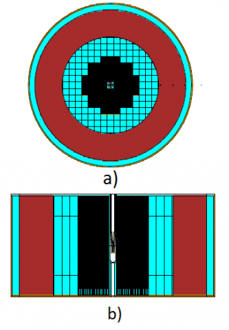
Figure 1. Horizontal (a) and vertical (b) ADS system where the 50-cm core (black) the 95 cm (35 cm lead in light blue, 50 cm graphite in magenta and 10 cm lead) mixed reflector, the 2 cm AISI steel vessel (yellow) are shown
The hybrid version (keff 0.974 – P = 550 kW) is instead composed by 59 fuel assemblies, each hosting 81 MOX pins (22% Pu/78% U) inspired by ALFRED project [2] where:
- The whole lead reflector has been replaced by 3 concentric layers: the first of 35-cm lead, followed by 50 cm of graphite and finally by 10 cm of lead
- The cooling system is provided by wider pipes, 0.5 cm in diameter, which allows to increase keff while maintaining the fast character of the core neutrons spectrum
In this section, we describe the design of a MOX fuelled fast ADS computed using MCNP-6 [3] and inspired by [4] to get a hybrid system simultaneously producing fast and thermal neutrons in different reactor regions. The horizontal and vertical sections are shown in fig. 1a and 1b where it is possible to see the 50-cm core (black), the reflector composed by three cylindrical layers: 35 cm of lead (light blue), 50 cm of graphite (magenta) followed by 10 cm of lead (light blue). The yellow region represents the 2 cm AISI steel vessel surrounding the whole system.
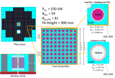
The core is composed by 59 hexahedral fuel assemblies of 11.6 x 111.6 x 150 cm 3. A single fuel assembly horizontal section is shown in fig. 2 where the 0,357 cm radius and 87 cm height MOX fuel pins (purple) cladded with 0,07 cm AISI steel (pink), the water cooling channels (white) embedded in a solid lead matrix (light blue) surrounded by 0.2 cm steel walls (yellow) are represented.
Figure 2. Fuel assembly horizontal section with MOX fuel pin (purple), cooling channels (white), steel claddings (pink), solid lead matrix (light blue) and steel walls (yellow)
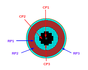
Figure 3. Horizontal ADS section with the in-core (CP1, CP2 and CP3) and out-core (RP1, RP2, RP3) irradiation positions
As already anticipated, the neutron source is provided by a 70 MeV - 1 mA proton beam from a cyclotron, impinging on conical beryllium target [5], giving about 8 x 10 14 n/sec [6].
In tab. 1, we report the integral fluxes values, the percentage of the flux above 0.5 MeV and the ratio R between the percentage of flux over 0.5 MeV and the percentage below 1 eV, for 3 core positions, CP1, CP2 and CP3, from closest to the source to farthest from the source (as shown in fig. 3).
Table 1. Integral flux, percentage of Φ> 0.5 MeV and R values for the in-core irradiation positions
|
Position |
Integral flux (n/cm 2/s) |
% Φ>0.5 MeV |
R |
|
CP1 |
1,12E+13 |
38 |
5.96E+2 |
|
CP2 |
7.25E+12 |
37 |
3.71E+2 |
|
CP3 |
4.36E+12 |
33 |
1.75E+2 |
In fig. 4 the energy flux distribution in the CP1, CP2 and CP3 in-core irradiation positions is reported.
Figure 4. In-core neutron flux energy distributions in the irradiation positions CP1 (blue), CP2 (red) and CP3 (yellow)
In tab. 2, we report the integral flux values and the relative percentage below 1 eV, for 3 positions in the reflector graphite shell, RP1, RP2 and RP3, from closest to the core to farthest from the core (as shown in fig. 3).
Table 2. Integral flux and % of Φ < 1eV values for the out-core irradiation positions
|
Position |
Integral flux (n/cm 2/s) |
% Φ < 1 eV |
|
RP1 |
1.85E+12 |
40.42 |
|
RP2 |
8.48E+11 |
83.97 |
|
RP3 |
3.87E+11 |
95.77 |
Figure 5. Out-core neutron flux energy spectra in the three sampling positions: RP1 (blue), RP2 (red) and RP3 (yellow)
In fig. 5 the energy flux distributions in the RP1, RP2 and RP3 out-core irradiation positions are shown.
The preliminary neutronic characterization of the reactor core has allowed the set-up of the geometry and composition of the fuel assembly and, therefore, the determination of the thermal power to be removed (fig. 6). On the basis of this parameters, a preliminary thermo-fluid-dynamic assessment, through simple analytical accounts, was made by Ansaldo Nucleare. In details, the following data have been determined:
- The operating pressure to maintain margins from boiling was chosen, and the calculation of the flow of the under-cooled water
- The calculation of the convective exchange coefficient inside the refrigerant pipes
- The calculation of the overall exchange coefficient and, as a consequence, the estimation of the temperature of the fuel necessary to evacuate the thermal power
- The calculation of the pressure drops through the refrigerant pipes, including also the lower inlet manifold and the outlet toward the upper one
The key features are thus summarized in fig. 6, in this case, a single FA was removed to obtain an irradiation channel inside the core; this could be easy possible thanks to the modularity of the facility.
Figure 6. Reference geometry and characteristics
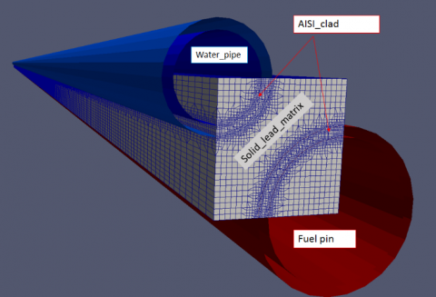
Figure 7. OpenFOAM geometry and mesh
Some of the above reported results have been fully verified [11] through a detailed CFD model used in steady-state conjugate heat transfer calculations performed by OpenFOAM-v1612+ and ANSYS FLUENT 17.0 CFD codes.
The geometrical model analysed by OpenFOAM-v1612+ includes only a lattice of the fuel assembly, as indicated in fig. 7, that shown the computational mesh created with respect to the water and fuel pin geometry. The computational mesh consists on about 4 Mcells (this value has been set on the basis of an ad-hoc sensitivity assessment).
The chtMultiRegionSimpleFoam solver has been used: this is a steady state solver for buoyant, turbulent fluid flow and solid heat conduction with conjugate heat transfer between solid and fluid regions.
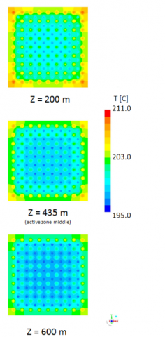
The results reported in fig. 8 indicate a relatively low temperature radial gradient along the whole analysed domain.
Figure 8. OpenFOAM temperature profile calculated at different axial positions
Figure 9. OpenFOAM temperature contours inside the computational domain
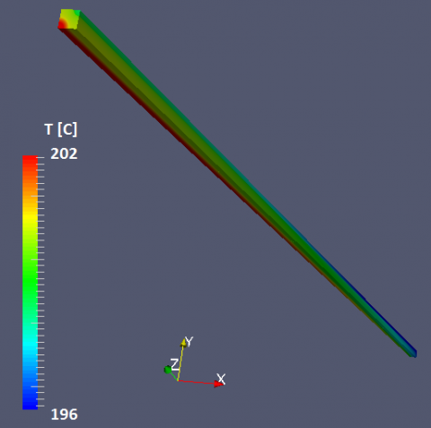
Figure 10. Temperature contours on FA
The geometrical model analysed by ANSYS FLUENT v17.0 includes the complete fuel assembly active zones and neglects the MOX cladding and the water pipe, but it takes into account the conductive heat exchange by a 1D model provided by the code (shadow wall feature).
The results were obtained with a SST k-ω turbulence model and a 12 Mnodes computational mesh; both these choices have been based on preliminary grid independence and turbulence (k-ε, RNG k-ε and SST k-ω) sensitivity analyses, performed in order to minimize the potential numerical errors.
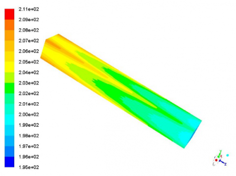
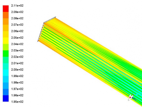
The obtained axial distribution of temperature in the active part of the fuel assembly is shown in fig. 10÷12.
Figure 11. Temperature contours on MOX cladding
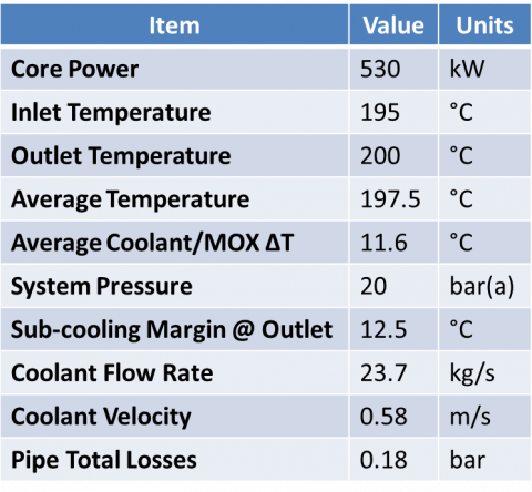
Table 3. Preliminary thermal-hydraulic characterization
The obtained numerical results are in very good agreement, both in terms of outlet temperatures and pressure drops (differences in the order of 2÷3%), with the already mentioned analytical simplified thermal-fluid-dynamic assessment performed by Ansaldo Nucleare.
Finally, a summary of the evaluated thermal-fluid-dynamic parameters is reported in the following tab. 3.
Figure 12. Temperature distribution for different axial FA sections
The conceptual design of the thermal-hydraulic aspects of a high safety ADS type research reactor, driven by a 70 MeV - 1 mA proton beam, has been presented. From this preliminary assessment, it can be confirmed that heat removal does not seem a great challenge for all the considered conditions.
In terms of future developments, in the near future it is planned to:
- extend the CFD model to the whole core, in order to calculate if the decay heat could be efficiently removed only by the external vessel radiation;
- set-up a model of the p→n Be converter, in order to perform a thermal-hydraulic characterization of the target, too.
This activity has been supported by INFN, Centro Fermi and partially funded by the European Atomic Energy Community's (Euratom) Seventh Framework Program FP7/2007-2011 under the Project CHANDA.
The CFD calculations developed in this work has been run on the HPC OCAPIE cluster (funded by Compagnia San Paolo).
[1] Mansani L., et al. (2014). An intrinsically safe facility for forefront research and training on nuclear technologies - general description of the system, Eur. Phys. J. Plus, Vol. 129, No. 65. DOI: 10.1140/epjp/i2014-14065-7
[2] Grasso G., et al. (2014). The core design of ALFRED, a demonstrator for the European lead-cooled reactors, Nuclear Engineering and Design, Vol. 228, pp. 287-301. DOI: 10.1016/j.nucengdes.2014.07.032
[3] Goorley T. (2014). MCNP6.1.1-beta release notes, LA-UR-14-24680.
[4] Panza F. et al. (2017). Influence of reflector materials and core coolant on the characteristics of accelerator driven systems, Annals of Nuclear Energy, Vol. 109, pp. 162-172. DOI: 10.1016/j.anucene.2017.05.005
[5] Ciotti M. (2014). An intrinsically safe facility for forefront research and training on nuclear technologies - Target profile optimization, Eur. Phys. J. Plus, Vol. 129, No. 67. DOI: 10.1140/epjp/i2014-14067-5
[6] Osipenko M., et al. (2013). Measurement of neutron yield by a 62 MeV proton beam on a thick Beryllium target, Nucl. Inst. Methods A, Vol. 723, No. 8. DOI: 10.1016/j.nima.2013.04.074
[7] Lomonaco G., et al. (2014). An intrinsically safe facility for forefront research and training on nuclear technologies - Burnup and transmutation, Eur. Phys. J. Plus, Vol. 129, No. 74. DOI: 10.1140/epjp/i2014-14074-6
[8] Panza F., et al. (2016). New infrastructure for studies of transmutation and fast systems concepts, 13th International Conference on Radiation Shielding (ICRS-13) & 19th Topical Meeting of the Radiation Protection & Shielding Division of the American Nuclear Society-2016 (RPSD-2016), Eur. Phys. J. Web of Conferences.
[9] Ripani M., et al. (2014). Study of an intrinsically safe infrastructure for training and research on nuclear technologies, Eur. Phys. J. Web of Conferences, Vol. 79, No. 02004. DOI: 10.1051/epjconf/20147902004
[10] CHANDA Consortium members, EU Challenges in nuclear data for the Safety of European Nuclear Facilities (CHANDA) project, from http://www.chanda-nd.eu/ accessed on 16 Aug. 2017
[11] Borreani W. (2017). Thermo-Hydraulic analysis by different CFD codes of some components of the primary system of Gen-IV lead-cooled demonstrator ALFRED, Ph.D. Thesis, DIME, University of Genova.