OPEN ACCESS
The study of laminar mixed convection is conducted in an air filled the lid-driven triangular cavity with a static circular cylinder. The circular cylinder is fixed at the center of the triangular cavity whose diameter is varied with respect to the height of the cavity and the variation is shown in terms of aspect ratio (AR = D/H). Sides of the cavity and the cylinder are maintained at uniform temperature whereas the cylinder temperature is considered higher than the walls of the cavity. Finite volume method is adopted to solve the governing equations. The present problem is investigated for different constraint parameters such as moving walls, different geometries of the hot wall, different aspect ratio, Richardson number (Ri) and Grashof number (Gr). The outcomes of the investigation reported that the average Nusselt number is found significant at AR = 1/2, Ri = 0.1 and Gr = 105. An Artificial Neural Network (ANN) tool is employed in the study to validate the obtained numerical results of stream functions and Nusselt number.
mixed convection, triangular enclosure, grashof number, richardson number, ANN
The study of convection flow in a two-dimensional lid driven enclosure has drawn the perceptible attention of researchers due to theseveral applications in the field of the microelectronics industry, nuclear power plant, solar energy system, food processing etc.[1-6]. The lid-driven cavity is a benchmark problem for the high heat transfer through the conjoint performances of free and forced convection heat transfer. Abundantof works have been conducted experimentally and numerically in a lid-driven cavity for different geometric configurations and various parameters. Moallemi and Jang [7] studied the lid-driven rectangular cavity. from the study, itwas found that the buoyancy force was significantly affected the fluid flow and heat transfer for higher value sof Prandtl number at constant Reynolds number (Re) and Grashof number (Gr).Mohamad and Viskanta [8] investigated the mixed convection in a shallow rectangular cavity. It was reported that the rate of heat transfer was increased with the decrease of Richardson number. Sivakumar et al. [9] numerically studied the mixed convection heat transfer in thelid-driven cavity for partial heating which placed on the left vertical wall. Oztop et al. [10] studied the lid driven rectangular cavity having left wall moving in its own plane with a circular cylinder which is placed inside the cavity. Results reported that the movement of lid plays an effective role in the enhancement of the rate of heat transfer. Billahet al. [11] numerically studied the heat transfer process in a lid-driven rectangular cavity with a heated circular cylinder placed at the center. The analysis was conducted for different Richardson numbers, cylinder diameters and solid-fluid thermal conductivity ratio. It was inferred that the heat transfer process was affected by the variation of Richardson number and the diameter of the hot cylinder.
Since the triangular geometry is commonly preferred for roofs (atticspaces) [12-17]. But, the study of convection heat transfer in triangular geometry has attained the prominent attention owing to its readily use in the engineering applications. Xu et al.[18] studied the laminar natural convection around a hot circular cylinder. The heat analysis was made for different aspect ratio, orientation and Rayleigh numbers. Yu et al. [19] underwent a study to exhibit the effect of variation of Prandtl number inside the cavity similar to the Xu et al. [18].A noticeable change was found in the heat transfer process with the variation of Prandtl number as well as the angle of inclination of the triangular cylinder.
In the present day's scenario, the adaptability and the acceptance of algorithms of artificial intelligence such as artificial neural networking, neuro-fuzzy logic, data mining etc. have attained a remarkable interest in the engineering fields because of its rapid calculation process, automated assumptions and easy handling of the process of calculation. Tahavoret al. [23] have implied the artificial neural networking (ANN) to predict the natural convection heat transfer and fluid flow from a column of cold horizontal circular cylinders. A lot of work has been carried out to solve the problems of ground source heat pump and solar assisted heat pump by using the artificial neural networking [30-35]. ANN has also widely been used in several fields of heat transfer and fluid flow [36-45] like natural and forced convection, boiling and condensation, pipe flow etc.
Numerous works have been premeditated in the context of mixed convection for different types of cavities for different boundary conditions so far. But the numerical study of the mixed convection on an equilateral triangle having anapex in the bottom and horizontal wall at the top (Fig.1) with a concentric hot circle has not been reported so far. Henceforth, the present study intends to investigate the heat transport phenomena by mixed convection insidea lid-driven triangular cavity with a circular cylinder placed concentrically for different Richard son number sand Grashof numbers. Also, a black box model has been created by implementing ANN algorithm and error analysis has been performed to check the effectiveness of ANN with CFD analysis.
2.1 Physical model
Figure 1. Schematic diagram of the physical model
Fig. 1 shows the physical model of the equilateral triangular cavity having height H and base l. Three different types of hot parts i.e. triangle, reverse triangle and a circular cylinder of diameter Dare placed concentrically at the center of the cavity having temperature Th. The ratio of the diameter of the cylinder or height of the inside hot triangle to the height of the triangular cavity is defined as the as pect ratio given byD/H.All the walls of the triangular cavity are considered to be iso thermally cold having temperature Tc(Tc< Th). The horizontal base wall of the cavity is given a translational velocity uo towards the positive x-direction. The cavity is filled with the working fluid air. (Pr = 0.71) and assume dall the properties to be constant except density variation in the y-direction (Boussinesq’sapproximation). The flow inside the cavity is assumed to be two-dimensional,steady and laminar. The governing equations of the problem are governed based on the following assumptions:
a) All walls areimpermeable
b) Radiation effect is negligible
c) Thefluid is incompressible
d) Thevariation in fluid propertieswith temperatureis negligible except the density variation.
2.2 Mathematical formulation
By using above considerations, the normalized governing equations are can be represented as follows:
Continuity equation:
$\frac{\partial U}{\partial X}+\frac{\partial V}{\partial Y}=0$ (1)
X-momentum equation:
$U \frac{\partial U}{\partial X}+V \frac{\partial U}{\partial Y}=-\frac{\partial P}{\partial X}+\frac{1}{\operatorname{Re}}\left(\frac{\partial^{2} U}{\partial X^{2}}+\frac{\partial^{2} U}{\partial Y^{2}}\right)$ (2)
Y-momentum equation:
$U \frac{\partial V}{\partial X}+V \frac{\partial V}{\partial Y}=-\frac{\partial P}{\partial Y}+\frac{1}{\operatorname{Re}}\left(\frac{\partial^{2} V}{\partial X^{2}}+\frac{\partial^{2} V}{\partial Y^{2}}\right)+\frac{G r}{\mathrm{Re}^{2}} \theta$ (3)
Energy equation:
$U \frac{\partial \theta}{\partial X}+V \frac{\partial \theta}{\partial Y}=\frac{\nabla^{2} \theta}{\text { Pr Re }}$ (4)
Boundary conditions:
For hot circular cylinder: θ = 1, U =V = 0
For the static cold walls:
θ = 0, U =V = 0 (5)
For the moving cold wall: θ = 0, U = 1, V = 0
The non-dimensional parameters are
$X=\frac{x}{H}, Y=\frac{y}{H}, U=\frac{u}{u_{0}}$$V=\frac{v}{u_{0}}, \theta=\frac{T-T_{c}}{T_{h}-T_{c}}, P=\frac{p}{\rho u_{0}^{2}}$Re$=\frac{u_{0} l}{\vartheta}, G r=\frac{g \beta\left(T_{h}-T_{c}\right) H^{3}}{\vartheta^{2}}$
$P r=\frac{\theta}{\alpha}$ (6)
where P is the dimensionless pressure, Re is the Reynolds number, Gr is the Grashof number and Pr be the Prandtl number.
3.1 Solution procedure
Fig. 2 displays the unevenly distributed unstructured triangular cells which are preferred for generating the grid system over the computational domain. With the help of mesh refinement, the number of mesh elements is concentrated near the walls where higher grid densities are preferred. A finite volume approach is adopted for solving the governing equation by keeping the convergence criteria of 10-6. Available commercial software FLUENT is used for solving the governing equations. The SIMPLE algorithm is used as pressure-volume correction scheme, PRESTO scheme is preferred for pressure discretization and the QUICK scheme is chosen for solving the momentum as well as energy equations. The local heat transfer rates for thehot wall are calculated using the local Nusselt number by using the standard relationship:
$N u_{x}=\frac{h S}{k}$ (7)
Figure 2. Unstructured triangular meshing of the domain with enlarged view of meshing
where h be the local heat transfer coefficient, S be the curve length (S=πD). To calculate the overall heat transfer rate for the concerned domain average Nusselt number is determined as
$N u=\frac{1}{S} \int N u_{x} d S$ (8)
The stream function can be defined as:
$u=\frac{\partial \psi}{\partial y}, v=-\frac{\partial \psi}{\partial x}$ (9)
Non-dimensionally it can be calculated as:
$\Psi=\frac{\psi}{\alpha}$ (10)
3.2 Grid independency testand code validation
A grid independency test is conducted to check the accuracy of the obtained numerical results for the chosen grid densityat Ra=107, Pr=0.71, A.R=1/3.The test is conducted fora grid size of 6400, 9800, 11500, 14730 and 16510. The accuracy of the grid size is determined by making the relative error analysis and finding out the deviation of average Nusselt number and magnitude of stream function (Ψ)which is shown in table 1.
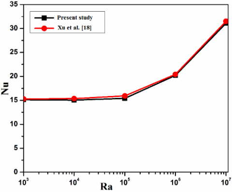
Figure 3(a). Validation of average Nusselt number for triangular cavity along with hot cylinder wall
Table 1. Relative error analysis of Nu and $\Psi_{\max }$ for different grid size
|
No. of elements |
Nu |
% Deviation |
$\Psi_{\max }$ |
% Deviation |
|
6400 |
14.3443 |
|
25.74 |
|
|
9800 |
14.2421 |
0.71 |
25.6929 |
0.183 |
|
11500 |
14.1903 |
0.36 |
25.3872 |
1.204 |
|
14730 |
14.1827 |
0.05 |
25.3756 |
0.046 |
|
16510 |
14.132 |
0.35 |
25.275 |
0.39 |
The minimum deviationin the average Nusselt number and stream function is found 0.05% and 0.046% respectively between the grid size of 11500 and 14730. Hence, 11500 is chosen to be the eventual grid sizeby keeping the numerical accuracy and computational time in consideration for all the cases throughout the study.
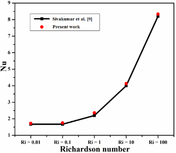
In order to validate the current code, the average Nusselt number of the hot wall for different Rayleigh numbers are compared with the available numerical results of Xu et al. [18] for Aspect ratio 1/2. Another study has been conducted to compare the result qualitatively and quantitatively with the results of Sivakumar et al. [9] in order to examine the case of lid movement. The validation of the present result is found quite satisfactory with the result of Xu et al. [18] and Sivakumar et al. [9] which are shown in Fig. 3 (a), 3(b) and 3(c).
Figure 3(b). Comparison of contours of streamlines and isotherms at Ri = 100
Figure 3(c). Comparison of average Nusselt number for different Ri at LH=1 and ε2 = 3/6
The study of a mixed convection is explored in an air filled lid driven triangular cavity. Numerical results of the current work are presented for lid movement, the shape of the heater, aspect ratio, Grashof number(Gr), Richardson number(Ri) and Reynolds number (Ri). The qualitative results are shown in terms of contours of streamlines and isotherms while the local and average Nusselt number are shown quantitatively.
4.1 Effect of position of the moving wall
Figure 4. Streamlines and isotherms of a cavity of AR 1/2 at Gr = 105, Ri = 0.25 for different moving walls
(a)
Figure 5(a). Variation of local Nusselt number along the curve length of the hot wall (a)
This section illustrates the effect of location of the moving wall of the cavity at aspect ratio 1/2, Gr =105 and Ri = 0.25. The analysis is made for three different casesas shown in Fig. 4 by setting individual wall of the triangular enclosure as the moving lid. It is noticed from the streamlines that the formation of vortexes rely upon the position of the moving wall and two rotating cells are formed inside the vortexes for each case. The rate of flow rotation is too changed with the location of the moving walls which is evaluated in terms of stream function. The flow rotation of the fluid is found higher when the horizontal wall of the cavity is made movable. The csimilar phenomenon is sensed for the corresponding isotherms in the distribution. It is observed that the location of boundary layer separation, the direction of thermal plume generation and propagation are different for the different
position of the moving wall. Furthermore, when the left wall is set to move, it is found that the average Nusselt number (Nu) is to reduce by 1.53% compared to top wall movement and on the contrarywhen the right wall is set to move then 0.001% reduction of the Nu is foundcompared to top wall movement.
(b)
Figure 5(b). Variation of average Nusselt number and maximum stream function at different location of the moving wall (b) for a cavity of AR = 1/2 , Gr = 105 and Ri = 0.25
Fig. 5(a) displays the variation of the local Nusselt number along with the curve length of the hot wall. It can be seen that the maximum value of the local Nusselt number is nearly same for all the three cases, but the location of maximum heat flux over the hot wall is varied. For the condition of the top moving wall, the maximum local Nusselt number is found at the top region of the circle. Whereas for left and right moving wall condition, the local Nusselt number is found maximum in the left middle and right middle portion of the circle. From this observation, it can also be inferred that the heat transfer rate becomes maximum at a place closer to the moving wall due to proper mixing of hot and cold fluid with the help of generated vortexes in the recirculation territory. However, from Fig. 5(b), there is a variation in average Nusselt number for each case but the variation is negligible. Hence, it is worthy to note that the variation of local Nusselt number for right and left moving wall are comparatively more than the top moving wall. It is happened, because, in the case of atop moving wall, the direction of buoyancy flow and lid movement are normal to each other whereas, in the case of left and right moving wall, the direction of lid movement and buoyancy flow are nearly parallel.
Hence, from this analysis, it is observed that the maximum heat transfer rate is obtained when the lid direction is normal to the direction of natural convection and the buoyancy flow direction is opposite to each other. Contrariwise, the heat transfer rate is decreased when their directions are same. Therefore, the further study is carried out only for the top lid wall case by omitting other two lid movements.
4.2 Effect of different geometries of hot cylinder
Figure 6. Streamlines and isotherms of cavities of different shapes of aspect ratio 1/4, at Gr = 5×10⁴ and Ri = 0.5
(c)
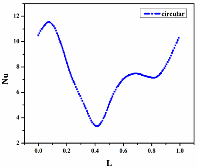
Figure 7.Variation of local Nusselt number along curve length of (a) triangle, (b) reverse triangle, (c) circle
In this part of the study, the effect of different shapes of the hot walls i.e. a triangle, reverse triangle and a circular cylinder inside the triangular cavity is studied. The results are obtained for fixed AR = 1/4, Gr = 5×10⁴, Ri = 0.5 and depicted in terms of streamlines and isotherms which are shown in Fig.6. The red dot on the circle in Fig.1 represents the starting point of the curve length which is measured in an anticlockwise direction from the starting point. In all cases, a single vortex is formed inside the cavity. The formed vortexes for the triangular and circular cases are pretty much elliptical, whereas, for the reverse triangular case it is stretched horizontally. The stream function is found the maximum for the triangular hot wall followed by acircle and the reverse triangle. It happens, because, the available flow area inside the cavity adjacent to the moving lid is more for the triangle and least for the reverse triangle. Along with this, the nature of boundary layer separation is found different for all the three cases due to the dissimilar alignment of the hot walls.
The variation in local Nusselt number along the hot walls is plotted in Fig.7. From the numerical calculation, it is found that the average Nusselt number is increased by 1.4% and 2.15% for the circular cylinder as compared to triangular and reverse triangular case respectively. Sincethe circular hot wall is more suitable compared to the triangle and the reverse triangle, hence, the further analysis is conducted for the top lid wall movement and for the circular hot wall.
4.3Effect of aspect ratio
TheFigure 8. Streamlines and isotherms for D/H= 1/2, D/H= 1/4, D/H= 1/6 at Ri = 0.25, Gr=5×10⁴
The variation in streamlines and isotherms owing to different aspect ratios i.e. AR = 1/2, 1/4, 1/6 respectively is illustrated in Fig.8 at fixed Ri = 0.25 and Gr = 5×10⁴. The different aspect ratiosof the cavity are obtained by varying the diameter of the cylinder for a constant enclosure height. It is observed from the contours of the streamlines that a single clockwise rotating vortex is formed inside the cavity at the lower value of the aspect ratio. As the aspect ratio is increased, the vortex is found to be flattened due to the reducing of the available flow area in the annulus. Eventually, when the aspect ratio is made 1/2, the available area for the flow is further reduced because of which the recirculation zone is found to be divided and hence the available single vortex is divided into two vortexes into both sides of the circle adjacent to the horizontal wall gives the rise to a dual-vortex flow situation.
Figure 9.Variation of averagemaximum stream function (a) and Nusselt number (a)with different aspect ratio at Ri = 0.5
Figure 10. Variation of local Nusselt number against the curve length for (a) AR = 1/6, (b) AR = 1/4 and (c) AR = 1/2 for Gr = 5×10⁴ and Ri = 0.25
When the aspect ratio is increased, as represented in Fig.9a, the magnitude of maximum stream function is found lesser because of the decreasing of the available flow space around the cylinder. On the other hand, from the isotherm contours, it is observed for the aspect ratio 1/4, that the thermal boundary layer gets separated from the top surface of the hot cylinder due to which a temperature plume is engendered and impinged towards the left corner of the enclosure. The isotherms are closely packed towards the hot wall and gradually get unpacked radially away from the hot wall. The isotherms are found closer to theleft wall of the enclosure compared to the right wall due to the forced convection effect caused by the lid
motion towards the positive x direction. As the aspect ratio is increased, the location of separation of the thermal boundary layer on the hot wall surface gets shifted and the temperature plume becomes closely packed.
Fig.10 shows the plots of local Nusselt number versus the curve length of the hot wall. It can be observed that the heat transfer rate is gradually increased towards the top portion of the cylinder after wardit starts declining towards the bottom due to the presence of the temperature plume. Heat transfer rate is found minimum at the bottom part of the cylinder wall. The heat transfer wavering is found to be increased along with the increase of the aspect ratio. Similarly, overall variation in the fluid flow and heat transfer rate can also be perceived from the average Nusselt number and the stream function which is shown in Fig. 9 (a). As mentioned before and displayed in Fig.8, the magnitude of stream function is decreased with the increase of the aspect ratio. Since, at the lower aspect ratio, the space between the hot body and cold wall is higher which increase the flow area of the fluid. However, the flow area is being decreased with the increase of thesize of the heated cylinder. The decrease in flow area causes the decrease of the rotational flow of the fluid but increases the heat transfer rate through the wall which is shown in Fig.9 (b). It is worthy to note that the average Nusselt number in increased by 25% for AR = 1/4 compared to AR = 1/6. However, the Nu at AR = 1/2 is 200% higher than the Nu at AR = 1/4 and 275% higher than that of Nu at AR = 1/2, respectively.
4.4Effect of Richardson number
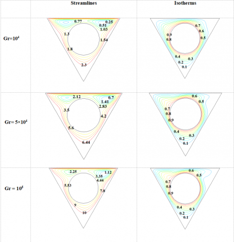
Figure 11. Streamlines and Isotherms of a cavity of AR = 1/4 at Gr = 105 and Ri = 0.1, Ri =0.25, Ri = 0.5, Ri = 1, Ri = 2.5, Ri = 5, Ri =10.
Fig.11 illustrates the effect of Richardson number (Ri) on streamlines and isotherms at aspect ratio 1/4 and Gr = 105. It is the parameter by which the ascendancy of the forced or free convection can be measured. Two streamline vortexes are formed due to the upward directed buoyancy driven current. The bigger one, on the right side, is rotated in clockwise and the smaller on the left side is in an anticlockwise direction. Also, the lid movement has amere effect on the heat transfer, hence uniform isotherm contours are found. Whereas, the left anti-clockwise vortex is started
diminishing its existence and ultimately it gets vanished due to the dominance of wall movement over the buoyancy flow as the Richardson number is decreased. It can be also observed from the streamline contours which clockwise rotating vortex are concentrated and attain circular shape. Consequently, the boundary layer separation induces the rise of temperature plume towards the top left region of the hot circle. At the intermediate value of Ri = 2.5, the temperature contours are getting widened towards theright.
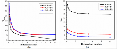
Figure 12. Variation of (a) local Nusselt number over the curve length of the hot circle (b) maximum stream function and (c) average Nusselt number over Richardson number for, Gr = 105
The variation in the local Nusselt number due to the different Richardson number is shown in Fig.12a. The magnitude of the local heat flux varies with the variation of Richardson number. It is well discernible from each case that the heat transfer rate is increased towards the top region of the cylinder while it is decreased due to the boundary layer separation in the top left region and towards the bottom. At a higher value of Richardson number, the rate of heat transfer is found lower as the natural convection is dominating over the forced convection. However, the heat transfer rate is getting strengthened with the decrease of Ri as the forced convection starts getting prevailed over the free
convection. The overall variation in the fluid flow and heat transfer rate can be observed from stream function and average Nusselt number respectively. The magnitude of the stream function is increased with the decrease of Richardson number and it is found maximum at AR = 1/6 as shown in Fig. 12b. On the other hand, as shown in Fig. 12c, the variation in average Nusselt number between AR = 1/6 and 1/4 is found to be very less compared to the AR = 1/2. The average Nusselt is enhanced with the decrease of Ri and found the maximum for AR = 1/2.
4.5Effect of Grashof number
Figure 13. Streamlines and isotherms for AR = 1/2 at Ri 0.5 and Gr = 104, Gr = 5×10⁴ , Gr = 105
Figure 14. Variation of Local Nusselt number along the curve length of the hot wall for different Grashof for AR = 1/2 and Ri = 0.5
The variation in streamlines and isotherm contours are demonstrated in Fig. 13 for a cavity of AR = 1/2 and Ri = 0.5 to depict the impact of Grashof number. As the Richardson number and aspect ratio are taken constantly for all the three cases, the temperature gradient is the sole parameter which affects the heat transfer process. From the streamlines
contours, it is seen that in each case, two clockwise rotating vortexes are formed towards the top corner. It is noticed that the vortexes are widened as the buoyancy driven current is stifled at lower Grashof number and hence the heat dissipation due to conduction has a superior role than the natural convection. With the increase of temperature of the hot wall, the buoyancy-driven flow is increased and so does the natural convection. As a result of which the widened vortexes are getting circular progressively.The variation in isotherms is found promising as compared to streamlines. In each case, thermal boundary separation is obtained,which gives rise to a temperature plume. It is worth to note that the plume is merely prominent at low Gr. With the increase of temperature gradient, the plume is getting more significant and protruded towards the top left corner. Along with that, the isotherms are found to be dragged towards left resulting in bringing the isotherms closer to the left wall and away from the right wall.
The variation in local Nusselt number is plotted against the curve length of the cylinder which is shown in Fig. 14. At low Gr, the temperature gradient between the walls is lesser due to which feeble convection is occurred inside the cavity. But, as the temperature gradient is increased with the increase of Grashof number, a strong convective heat transfer ensues which enhances the flow rate of the fluid as well the heat transfer rate. This can be comprehended in Fig. 14 where the maximum value of local Nusselt at higher Grashof number signifies the higher rate of heat transfer.
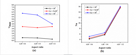
Similarly, the influence of Grashof number onthe overall fluid flow and heat transfer is calculated in terms of maximum stream function and average Nusselt number respectively for cavities of A.R= 1/2,1/4 and 1/6 at different Richardson numbers as shown in Fig. 15. From the results, it is worth to notify that for Ri = 0.1 and A.R = 1/2,a substantial increase of 14.16% and 21.75% in the average Nusselt number is found with the increase of Grashof number from 104 to 5×10⁴ and then to 105 respectively. Correspondingly the percentage proliferations of average Nusselt number for AR 1/4 is found to be 20.56, 24.64 and for AR 1/6 is 21.5, 33.82 when the Grashof number is varied from 104 to 5×10⁴ and from 104 to 105 respectively.
Figure 15. Variation of maximum stream function (a), (c), (e) and average Nusselt number (b), (d), (f) with different Grashof numbers for Aspect ratio 1/2, 1/4 and 1/6 respectively
4.6 Artificial neural networking
Past few decades, artificial intelligence by means of several computer algorithms has been showing a remarkable trystin engineering applications. The algorithm collects data and learns by experience and provides the other probable data. Algorithms like Genetic Algorithm, Artificial Neural Networking, Fuzzy-Logic, data mining comes under this category. In this study, artificial neural networking algorithm is used for ease of calculation and less computational time requirement.
4.6.1ANN Architecture
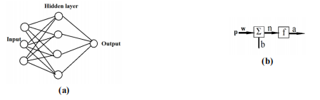
A neural network basically consists of three layers i.e. input layer, hidden layers, and anoutput layer. In this study a multilayer perceptron network, shown in Fig.17, having three inputs, four hidden layers and one output layer is chosen. Feed forward back propagation algorithm is chosen for training and Levenberg –Marquardt (translm) learning rules is adopted for the sake of its accurate and faster calculation behavior. Back propagation algorithm is chosen because it is so designed that it reduces the mean square error between the outcome predicted and desired.
Figure 16 .(a) Structure of a feed forward ANN network, (b) An artificial neuron
In this network, input parameters are circle diameter, Gr, and Ri and output parameters are average Nu and maximum stream function. Tangent sigmoid function and logistic sigmoid functions are chosen as the transfer function. Weight and bias values are adjusted to minimize the error. The computation procedure is like,
i) Weights and thresholds are initialized to random values.
ii) Set of input and desired output data is provided for training. Out of total data provided 70% are set for training and 15% each for validation and testing purpose.
iii) Output at hidden and the output layer is calculated.
iv) Output layer error is calculated.
v) Weights and thresholds in the output and hidden layers are adjusted.
vi) Iteration continues until the error value is reduced and an acceptable value is obtained.
In order to check the performance of the network, RMS and fraction of variance value are calculated using the desired output and the output obtained from ANN analysis. These are given as:-
i)$R M S=\sqrt{\frac{\sum_{j=1}^{n}\left[T_{j}-O_{j}\right]^{2}}{n}}$ ,
RMS = Root mean squared, Tj = Target output, Oj = Desired output, n = number of data
ii) $R^{2}=1-\frac{\sum_{j}\left[T_{j}-O_{j}\right]^{2}}{\sum_{j}\left(O_{j}\right)^{2}}$ , R2 = fraction of variance
It is taken care to minimize the RMS value and maximize the R2 value.
The problem of mixed convection heat transfer in a lid-driven triangular cavity is taken to imply the feasibility of ANN scheme and determine anew set of outputs in terms of Nusselt number and the maximum stream function.
Figure 17. Comparision between average Nusselt number obtained from ANN and CFD
MATLAB commercial software is used to simulate the neural network. Simulation is carried for all the cases those are analyzed earlier in this study by CFD i.e. Fluent. Here in Table 2, the comparison between the outputs obtained in CFD analysis and ANN analysis for a cavity of A.R 1/4 at Gr 104 are illustrated. From the table, the accuracy of the outcomes is pretty evident with very less error hence justifying the feasibility of ANN. Comparison of the Nu value between CFD and ANN is plotted in Fig. 17 which is displayed anagreeable understanding between them.
Table 2. Comparison of outputs of CFD and ANN analysis
|
Gr |
Ri |
Nu from CFD |
Nu from ANN |
%ge error |
Ψmax from CFD |
Ψmax from ANN |
%ge error |
|
104 |
0.1 |
7.10 |
6.79 |
4.37 |
7.86 |
7.32 |
6.87 |
|
|
0.25 |
6.25 |
6.53 |
-4.58 |
4.15 |
4.17 |
-0.48 |
|
|
0.5 |
6 |
6.24 |
-4.07 |
3 |
2.84 |
5.33 |
|
|
1 |
5.97 |
5.91 |
0.91 |
2.16 |
2 |
7.4 |
|
|
2.5 |
5.75 |
5.63 |
2.06 |
1.42 |
1.53 |
-7.74 |
|
|
5 |
5.72 |
5.67 |
0.73 |
1.05 |
1.07 |
-1.9 |
|
|
10 |
5.62 |
5.1 |
9.15 |
0.81 |
0.78 |
3.7 |
Figure 18. Overall correlation coefficients of the developed network
Table 3. Root mean square error and variance for Nusselt number and maximum stream function
|
|
Nu |
Ψmax |
|
RMSE |
0.3008 |
0.9171 |
|
R2 |
0.9999909 |
0.9999272 |
In order to check the closeness of outcomes, two statistical indicators R2 and RMS (root mean square error) are used to evaluate the fitting of the network as depicted in table 3. R-square value is very close to 1 which signifies an excellent correspondence between the ANN results and the results obtained from CFD for both average Nusselt number and maximum stream function. The comprehensive correlation coefficient of the selected network model is represented in Fig. 18.
A numerical analysis is done on the mixed convection heat transfer phenomena on an equilateral lid-driven triangle cavity with a circular cylinder placed concentrically inside it. The cavity is considered to be filled with anair of Pr = 0.71. Basically, the effects of the position of the moving wall, geometry of the hot cylinder, aspect ratio, Grashof number and Richardson number are observed which can be inferred shortly as:-
1. Maximum heat transfer rate is obtained when the lid direction is normal to the direction of natural convection, and when the direction of lid movement and buoyancy flow direction are opposite to each other. However, the heat transfer rate is decreased when their directions are same.
2. The average Nusselt number is found the maximum for the circular cross-section of the hot wall, as it is having the maximum surface area as compared to the triangle and reverse triangle.
3. With the increase of Grashof number, very less variation is found in the appearance of streamline contours whereas a significant increment in the magnitude is found and also the temperature plume starts getting more pointed towards the top left corner due to the increase of natural convection effect.
4. The flow area is more for the cavities with the smaller aspect ratio. Hence the recirculation vortex is generated in the bigger size. With the increment of aspect ratio, the flow area inside the cavity decreases gradually as a result, the vortex is flattened and ultimately another anticlockwise circulating vortex is formed at high aspect ratio.
5. The average Nusselt number is increased with the increase of Grashof number, as the natural convection effect is increased with the increase of temperature gradient. It is also increased with the increment of aspect ratio and Richardson number due to increased hot surface area and increased forced convection effect respectively.
6.Artificial neural networking is used as well to conduct the analysis and results are obtained for all the cases. A pretty satisfactory resemblance is found in between the results of CFD analysis and ANN analysis.
|
H |
Height of the triangle |
|
D |
Diameter of the circle ,m |
|
T |
Temperature, K |
|
g |
Acceleration due to gravity, m/s2 |
|
K |
Thermal conductivity |
|
H |
Heat transfer coefficient, |
|
W/m2 |
K |
|
Pr |
Prandtl number |
|
Gr |
Grashof number |
|
L |
Non-dimensional local coordinate |
|
u, v |
Velocity components, ms−1 |
|
U,V |
Non dimensional velocity component |
|
X, Y |
Dimensionless co-ordinates |
|
l |
Length of side of triangle |
|
Th |
Hot wall temperature, K |
|
Tc |
Cold wall temperature, K |
|
Nu |
Average Nusselt number |
|
S |
Curve length |
|
p |
Pressure, KPa |
|
P |
Dimensionless pressure |
|
Re |
Reynolds number |
|
Greek Symbols |
|
|
α |
Thermal diffusivity, m2 s |
|
μ |
Dynamic viscosity, Nsm−2 |
|
β |
Thermal expansion coefficient, K−1 |
|
θ |
Dimensionless temperature |
|
k |
Thermal conductivity, Wm−1 K−1 |
|
υ |
Kinematic viscosity, m2 s |
|
ψ |
Stream function, s−1 |
|
ρ |
Density, kgm−3 |
|
Subscripts |
|
|
h |
Hotwall |
|
c |
Cold wall |
[1] Khanafer K., Chamkha A.J. (1998). Mixed convection flow in a lid-driven enclosure filled witha fluid-saturated porous medium, Int. J. Heat Mass Transfer, Vol. 42, pp. 2465–81.
[2] Alleborn N., Raszillier H., Durst F. (1999). Lid-driven cavity with heat and mass transport, Int. J. Heat Mass Transfer, Vol. 42, pp. 833–53.
[3] Khanafer K., Vafai K. (2002). Double-diffusive mixed convection in a lid-driven enclosure filled with a fluid-saturated porous medium, Numer. Heat Transfer, Part A, Vol. 42, pp. 465–86.
[4] Iwatsu R., Hyun J.M., Kuwahara K. (1993). Mixed convection in a driven cavity with a stable vertical temperature gradient, Int. J. Heat Mass Transfer, Vol. 36, pp. 1601–08.
[5] Al-Amiri A., Khanafer K., Bull J., Pop I. (2007). Effect of sinusoidal wavy bottom surface on mixed convection heat transfer in a lid-driven cavity, Int. J. Heat Mass Transfer, Vol. 50, pp. 1771–80.
[6] Al-Amiri A., Khanafer K. (2011). Fluid–structure interaction analysis of mixed convection heat transfer in a lid-driven cavity with a flexible bottom wall, Int. J. Heat Mass Transfer, Vol. 54, pp. 3826–36.
[7] Moallemi M.K., Jang K.S. (1992). Prandtl number effects on laminar mixed convection heat transfer in a lid-driven cavity, Int. J. Heat Mass Transfer, Vol. 35, pp. 1881-92.
[8] Mohamad A.A., Viskanta R. (1993). Flow and thermal structures in a lid-driven cavity heated from below, Fluid Dynamics Research, Vol. 12, pp. 173-84.
[9] Sivakumar V., Sivasankaran S., Prakash P., Lee J. (2010). Effect of heating location and size on mixed convection in lid-driven cavities, Computers and Mathematics with Applications, Vol. 59, pp. 3053-65.
[10] Oztop H.F., Zhao Z., Yu B. (2009). Fluid flow due to combined convection in lid-driven enclosure having circular body, Int. J. Heat Fluid Flow, Vol. 30, pp. 886–901.
[11] Billah M.M., Rahman M.M., Sharif U.M., Rahim N.A., Saidur R., Hasanuzzaman M. (2011). Numerical analysis of fluid flow due to mixed convection in a lid-driven cavity having a heated circular hollow cylinder, Int. Commun. Heat Mass Transf, Vol. 38, pp. 1093–1103.
[12] Poulikakos D., Bejan A. (1983). The fluid dynamics of an attic space, J. Fluid Mech, Vol. 131, pp. 251–69.
[13] Asan H., Namli L. (2000). Laminar natural convection in a pitched roof of triangular cross-section: Summer day boundary conditions, Energ. Building, Vol. 33, pp. 69–73.
[14] Asan H., Namli L. (2001). Numerical simulation of buoyant flow in a roof of triangular cross-section under winter day boundary conditions, Energ. Building, Vol. 33, pp. 753–57.
[15] Tzeng S.C., Liou J.H., Jou R.Y. (2005). Numerical simulation-aided parametric analysis of natural convection in a roof of triangular enclosures, Heat Transfer Engineering, Vol. 26, pp. 69–79.
[16] Varol Y., Koca A., Oztop H.F. (2007). Natural convection heat transfer in gambrel roofs, Build. Environment, Vol. 42, pp. 1291–97.
[17] Oztop H.F., Varol Y., Koca A. (2007). Laminar natural convection heat transfer in a shed roof with or without eave for summer season, Applied Thermal Engineering, Vol. 27, pp. 2252–65.
[18] Xu X., Yu Z., Hu Y., Fan L., Cen K. (2010). A numerical study of laminar natural convective heat transfer around a horizontal cylinder inside a concentric air-filled triangular enclosure, International Journal of Heat and Mass Transfer, Vol. 53, pp. 345–55.
[19] Yu Z.T., Hu Y.C., Fan L.W., Cen K.F. (2010). A parametric study of Prandtl number effects on laminar natural convection heat transfer from a horizontal circular cylinder to its coaxial triangular enclosure, Numerical Heat Transfer Part A, Vol. 58, pp. 564–80.
[20] Khanafer K., Aithal S.M. (2013). Laminar mixed convection flow and heat transfer characteristics in a lid driven cavity with a circular cylinder, International Journal of Heat and Mass Transfer, Vol. 66, pp. 200–09.
[21] Islam A.W., Sharif M.A.R., Carlson E.S. (2012). Mixed convection in a lid driven square cavity with an isothermally heated square blockage inside, Int. J. Heat Mass Transfer, Vol. 55, pp. 5244–55.
[22] Oztop H.F., Zhao Z., Yu B. (2009). Fluid flow due to combined convection in lid-driven enclosure having circular body, Int. J. Heat Fluid Flow, Vol. 30, pp. 886–901.
[23] Tahavvor A.R., Yaghoubi M. (2012). Analysis of natural convection from a column of cold horizontal cylinders using Artificial Neural Network, Applied Mathematical Modelling, Vol. 36, pp. 3176–88.
[24] Mohanraja M., Jayaraj S., Muraleedharan C. (2012). Applications of artificial neural networks for refrigeration, air-conditioning and heat pump systems—A review, Renewable and Sustainable Energy Reviews, Vol. 16, pp. 1340–58.
[25] Tahavvor A.R., Yaghoubi M. (2011). Prediction of frost deposition on a horizontal circular cylinder under natural convection using artificial neural networks, International Journal of Refrigeration, Vol. 34, pp. 560–66.
[26] Sanaye S., Asgari H. (2013). Thermal modeling of gas engine driven air to water heat pump systems in heating mode using genetic algorithm and Artificial Neural Network methods, International Journal of Refrigeration, Vol. 36, pp. 2262–77.
[27] Tahavvor A.R., Yaghoubi M. (2008). Natural cooling of horizontal cylinder using Artificial Neural Network (ANN), International Communications in Heat and Mass Transfer, Vol. 35, pp. 1196–1203.
[28] Kargar A., Ghasemi B., Aminossadati S.M. (2011). An Artificial Neural Network approach to cooling analysis of electronic components in enclosures filled with nanofluids, Journal of Electronic Packaging, Vol. 133, pp. 1011010-9.
[29] Yang K.T. (2008). Artificial Neural Networks, ANN: A new paradigm for thermal science and engineering, Journal of Heat Transfer, Vol. 130, pp. 093001-19.
[30] Esen H., Inalli M., Sengur A., Esen M. (2008). Forecasting of a ground-coupled heat pump performance using neural networks with statistical data weighting pre-processing, International Journal of Thermal Sciences, Vol. 47, pp. 431–41.
[31] Esen H., Inalli M., Sengur A., Esen M. (2008). Performance prediction of a ground-coupled heat pump system using artificial neural networks, Expert Systems with Applications, Vol. 35, pp. 1940–48.
[32] Esen H., Ozgen F., Esen M., Sengur A. (2009). Artificial neural network and wavelet neural network approaches for modelling of a solar air heater, Expert Systems with Applications, Vol. 36, pp. 11240–48.
[33] Esen H., Inalli M., Sengur A., Esen M. (2008). Artificial neural networks and adaptive neuro-fuzzy assessments for ground-coupled heat pump system, Energy and Buildings, Vol. 40, pp. 1074–83.
[34] Esen H., Esen M., Ozsolak O. (2015). Modelling and experimental performance analysis of solar-assisted ground source heat pump system, Journal of Experimental & Theoretical Artificial Intelligence, DOI: 10.1080/0952813X.2015.1056242
[35] Scalabrin G., Piazza L. (2003). Analysis of forced convection heat transfer to supercritical carbon dioxide inside tubes using neural networks, Int. J. Heat Mass Transfer, Vol. 46, pp. 1139–54.
[36] Varol Y., Avci E., Koca A., Oztop H. (2007). Prediction of flow fields and temperature distributions due to natural convection in a triangular enclosure using Adaptive-Network-Based Fuzzy Inference System (ANFIS) and Artificial Neural Network (ANN), Int. Comm. Heat Mass Transfer, Vol. 34, pp. 887–96.
[37] Tahavvor A.R., Yaghoubi M. (2008). Natural cooling of horizontal cylinder using Artificial Neural Network (ANN), Int. Commun. Heat Mass Transfer, Vol. 35, pp. 1196–1203.
[38] Scalabrin G., Condosta M., Marchi P. (2006). Modeling flow boiling heat transfer of pure fluids through artificial neural networks, Int. J. Therm, Science, Vol. 45, pp. 643–63.
[39] Scalabrin G., Condosta M., Marchi P. (2008). Flow boiling of pure fluids, Int. J. Therm. Science, Vol. 45, pp. 739–51.
[40] Balcilar M., Dalkilic A.S., Wongwises S. (2011). Artificial neural network techniques for determination of condensation heat transfer characteristics during downward annular flow of R134a inside a vertical smooth tube, Int. Comm. Heat Mass Transfer, Vol. 38, pp. 75–84.
[41] Shayya W.H., Sablani S.S. (1998). An artificial neural network for non-iterative calculation of the friction factor in pipeline flow, Comput. Electron, Agriculture, Vol. 21, pp. 219–28.
[42] Hasiloglu A., Yilmaz M., Comakli O., Ekmekci I. (2004). Adaptive neuro-fuzzy modeling of transient heat transfer in circular duct air flow, Int. J. Therm. Science, Vol. 43, pp. 1075–90.
[43] Firat M., Goungor M. (2007). River flow estimation using adaptive neuro-fuzzy inference system, Math. Comput. Simulation, Vol. 75, pp. 87–96.
[44] Kuehn T.H. (1980). Goldstein RH. Numerical solution to the Navier–Stokes equations for laminar natural convection about a horizontal isothermal circular cylinder, Int. J. Heat Mass Transfer, Vol. 23, pp. 971–79.
[45] Reymond O., Murray D.B., O’Donovan T.S. (2008). Natural convection heat transfer from two horizontal cylinders, Exp. Therm. Fluid Science, Vol. 32, pp. 1702–09.